Diatron Aquila Service Manual PDF – Hematology Analyzer Repair Guide Download
Original price was: $85.00.$16.95Current price is: $16.95.
Professional service manual for Diatron Aquila hematology analyzer (models A1-1 and A1-2). Complete 138-page technical documentation covering automated 3-part differential blood cell counter. Includes detailed disassembly procedures, calibration instructions, fluidic system diagrams, component replacement, and preventive maintenance schedules. Essential resource for biomedical technicians servicing clinical hematology analyzers measuring WBC, RBC, PLT, and HGB parameters.
Description
Diatron Aquila Service Manual PDF – Hematology Analyzer Repair Guide Download
DESCRIPTION:
Diatron Aquila Service Manual – Professional Hematology Analyzer Maintenance Guide
This comprehensive Diatron Aquila service manual PDF is the factory-authorized technical resource for biomedical equipment technicians (BMETs) and certified service engineers maintaining the Diatron Aquila hematology analyzer. This official hematology analyzer repair guide download provides complete documentation for professional service, calibration, and component replacement of this advanced 3-part differential analyzer service documentation system.
Models Covered:
- Diatron Aquila A1-1 (Standard AC-powered model)
- Diatron Aquila A1-2 (Battery-equipped portable model with charger board)
System Overview:
Diatron Aquila Automated Hematology Analyzer
- Type: Fully automated 3-part differential hematology analyzer
- Application: In vitro diagnostic use in clinical laboratories
- Technology: Impedance-based cell counting with optical hemoglobin measurement
- Parameters Measured:
- WBC (White Blood Cells) – 3-part differential leukocyte count
- RBC (Red Blood Cells/Erythrocytes)
- PLT (Platelets)
- HGB (Hemoglobin) – Optical measurement system
- Sample Type: Whole blood (capillary, venous, or arterial)
- Measurement Chambers: Dual aperture system (80 µm WBC, 70 µm RBC)
- Software Version: Version 2.0 and onwards
- Manufacturer: Diatron MI Zrt., Budapest, Hungary
- Manual Edition: November 2020, Version A
This professional automated blood cell counter technical manual is designed for clinical laboratories requiring accurate and reliable complete blood count (CBC) analysis.
Complete Manual Contents:
Chapter 1: Introduction (Pages 1-1 to 1-11)
1.1 Intended Use:
- Clinical diagnostic applications
- Laboratory settings and requirements
- Operational scope and limitations
1.2 Typographical Conventions:
- 1.2.1 Terminology: Technical language and definitions
- 1.2.2 Display of Warnings and Notes: Safety information presentation
- 1.2.3 Used Warning Symbols: Standard safety icons and meanings
- 1.2.4 Other Symbols: Operational indicators and markers
1.3 Qualification of Field Service Engineer:
- Required training and certifications
- Technical competency requirements
- Factory authorization protocols
1.4 Safety Instructions:
- 1.4.1 General Safety:
- Equipment handling precautions
- Operational safety protocols
- Personal protective equipment (PPE) requirements
- 1.4.2 Electrical Safety:
- High voltage warnings
- Power supply precautions
- Electrostatic discharge (ESD) protection measures
- Grounding requirements
- 1.4.3 Biological Safety:
- Infection control protocols
- Biohazard material handling
- Blood sample safety procedures
- Contamination prevention
- 1.4.4 Disposal and Decontamination:
- Infectious waste disposal regulations
- Decontamination procedures
- Environmental safety compliance
- Cleaning solution specifications
1.5 Positions of Safety Labels and Instrument Labels:
- Model identification (A1-1 and A1-2)
- Safety label locations
- Warning label specifications
Chapter 2: Basic Functions and Service Menu (Pages 2-13 to 2-18)
2.1 Logging in as Service User:
- Service account credentials
- Access level permissions
- User switching procedures
2.2 Overview of General Utilities:
- Software menu navigation
- Service-specific features access
- Interface overview
2.3 Service Specific Functions:
- 2.3.1 Quality Control:
- Auto QC procedures
- Reference value settings
- Production calibration protocols
- 2.3.2 Calibration:
- Manual calibration screen interface
- Service factor adjustments
- User factor modifications
- Calibration history tracking
- 2.3.3 Exporting Logs and Collecting Diagnostic Data:
- Event log export procedures
- CSV log generation
- Collect file creation for remote diagnostics
- Date range selection
- 2.3.4 Maintenance:
- Service function access
- Maintenance scheduling
- System verification procedures
2.4 System Preferences:
- Configuration settings
- Parameter adjustments
- System customization options
Chapter 3: System Description (Pages 3-21 to 3-41)
3.1 General Overview:
- Complete system architecture
- Functional block description
- Operating principles
3.2 Instrument Description:
- 3.2.1 Front View: External interface components
- 3.2.2 Rear View: Rear panel connections and interfaces
- 3.2.3 Construction View – Front:
- Sample door mechanism
- Needle wash head assembly
- Sampling needle positioning
- Needle opto board location
- Needle mechanics and axis system
- Analyzer frame assembly
- Base plate construction
- Reagent pack compartment
- Needle stepper motor
- Lower board PCB
- Charger board (A1-2 model)
- Power supply electronics
- Shear valve stepper motor
- Battery unit (A1-2 model)
- 3.2.4 Construction View – Right Side:
- Dilutor unit assembly
- Two-syringe dilutor system
- Valve block configuration
- Measuring unit (amplifier and chamber block)
- 3.2.5 Construction View – Left Side:
- Left-side component access
- Additional subsystem locations
3.3 Operation of the Fluidic System:
- Fluid flow pathways
- Sample aspiration and dilution
- Reagent delivery systems
- Waste management
- 3.3.1 Standby, Cleaning, Preparing for Shipment:
- System shutdown procedures
- Cleaning protocols
- Shipment preparation
3.4 System Control Operation:
- 3.4.1 Front Cover Unit Construction: Display and control panel assembly
- 3.4.2 Boards and Their Descriptions:
- Main control board specifications
- Power board functions
- Amplifier board details
- Sensor boards
- 3.4.3 Other Detecting Components:
- Optical sensors
- Position sensors
- Pressure sensors
3.5 Main Mechanical Units with Opto Sensors and Fluidic Parts:
- 3.5.1 Sample Moving Unit: Automated sample handling mechanism
- 3.5.2 The Shear Valve and Its Opto Sensor Board: Precision flow control
- 3.5.3 Dilutor Blocks: Sample and reagent dilution systems
- 3.5.4 Valve Block: Fluidic switching and routing
Chapter 4: Adjustments (Pages 4-43 to 4-54)
This Aquila A1-1 A1-2 maintenance manual provides detailed adjustment procedures:
4.1 Front Panel Calibration:
- Touchscreen calibration requirements
- 4.1.1 Re-calibration Procedure: Step-by-step calibration process
4.2 Shear Valve Adjustments:
- 4.2.1 Adjusting the Thumb Screw: Mechanical adjustment procedure
- 4.2.2 Adjusting Belt Tension: Proper belt tensioning techniques
4.3 Adjustment of Needle Positions:
- 4.3.1 Needle Motor Settings: Stepper motor configuration
- 4.3.2 Sampling Position: Precise needle positioning calibration
4.4 Calibration of the Sample Moving Unit:
- 4.4.1 Cap Piercing Position: Sample tube access calibration
- 4.4.2 End Position Calibration: Movement limit settings
4.5 Adjustment of the Wash Head:
- Wash head positioning
- Cleaning cycle optimization
4.6 Reagent Sensor Calibration:
- Reagent level detection
- Sensor threshold settings
Chapter 5: Removal and Replacement of Main Units (Pages 5-55 to 5-81)
5.1 Removing Front, Top and Side Covers:
- Access panel removal procedures
- Fastener locations
- Cover reassembly
5.2 Replacing the Sampling Needle:
- Needle removal procedure
- Proper needle installation
- Alignment verification
5.3 Replacing the Wash Head:
- Wash head disassembly
- Installation procedures
5.4 Removing the Reagent Pack Compartment:
- Reagent bay access
- Component removal
5.5 Shear Valve Removal and Reassembly:
- Complete valve assembly removal
- 5.5.1 Shear Valve Teflon Tube Replacement: Tubing service
- 5.5.2 Removing the Shear Valve Drive: Motor and drive mechanism
5.6 Measuring Unit:
- 5.6.1 Aperture Removal: 80 µm (WBC) and 70 µm (RBC) aperture service
- 5.6.2 Measuring Chamber Unit Removal: Chamber block disassembly
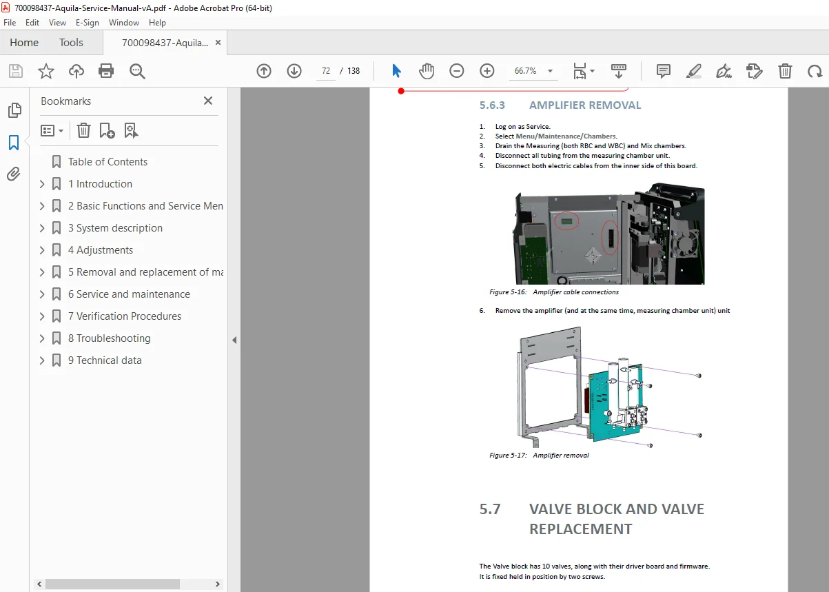
- 5.6.3 Amplifier Removal: Pre-amplifier board replacement
5.7 Valve Block and Valve Replacement:
- Fluidic valve servicing
- Valve block maintenance
5.8 Syringe Replacement:
- Dilutor syringe service
- Proper syringe installation
5.9 Pump Replacement:
- Vacuum pump service
- Pump installation procedures
5.10 Reagent Sensor Replacement:
- Sensor removal and installation
- Calibration after replacement
5.11 Blood Sensor Replacement:
- Sample detection sensor service
- Sensor positioning
5.12 Sample Moving Unit:
- 5.12.1 Replacing the Sample Holder: Holder mechanism service
- 5.12.2 Replacing the Sensor Board: Opto sensor board replacement
5.13 Replacement of Electronic Parts:
- 5.13.1 Replacement of the Lower Board: Main control board service
- 5.13.2 Replacement of the Pressure Sensor Board: Sensor board replacement
- 5.13.3 Fuse Replacement: Fuse specifications and procedures
- 5.13.4 Battery and Battery Charger Board Replacement: (A1-2 model)
- 5.13.5 Replacement of the Charger Board: Charger electronics service
- 5.13.6 Front Panel Electronics: Display and interface board replacement
Chapter 6: Service and Maintenance (Pages 6-85 to 6-90)
6.1 User Maintenance:
- 6.1.1 Periodic User Maintenance: Regular cleaning and checks
- 6.1.2 Elective User Maintenance: Optional maintenance procedures
6.2 Preventive Maintenance:
- Comprehensive PM schedule
- 6.2.1 Sampler Unit Preventive Maintenance: Sampling system PM
- 6.2.2 Sample Moving Unit Preventive Maintenance: Motion system PM
- 6.2.3 Measuring Unit Preventive Maintenance: Chamber and aperture PM
- 6.2.4 Syringe Preventive Maintenance: Dilutor syringe PM schedule
- 6.2.5 Syringe Drive Preventive Maintenance: Motor and drive PM
- 6.2.6 Reagent Pack Sensor Replacement: Sensor PM schedule
6.3 System Verification:
- Post-service verification procedures
- Performance validation tests
Chapter 7: Verification Procedures (Pages 7-93 onwards)
7.1 Blank Measurement:
- Background noise testing
- Baseline verification
7.2 Stress Run:
- System reliability testing
- Long-duration validation
7.3 Probe Voltages:
- Electrical system verification
- Voltage measurement procedures
7.4 Self-Test:
- Automated diagnostic routines
- System integrity checks
Additional Verification Procedures:
- 7.5 Motor Testing and Calibration: Stepper motor verification
- 7.6 Pumps and Valves: Fluidic system testing
File Details:
| Specification | Details |
|---|---|
| Manual Name | Diatron Aquila Service Manual |
| Equipment | Automated 3-Part Differential Hematology Analyzer |
| Models | A1-1 (Standard), A1-2 (Battery-Equipped Portable) |
| Parameters | WBC (3-part), RBC, PLT, HGB |
| Year | November 2020 (Manual Version A) |
| Software | Version 2.0 and onwards |
| Total Pages | 138 pages |
| PDF Quality | High-quality technical manual with detailed diagrams |
| File Size | 11.4 MB |
| Language | English |
| Publisher | Diatron MI Zrt., Budapest, Hungary |
| Manual Type | Official Factory Service Manual |
Who Needs This Manual?
This clinical hematology system troubleshooting guide is essential for:
- ✓ Certified biomedical equipment technicians (BMET/CBET)
- ✓ Clinical laboratory equipment specialists
- ✓ Hospital clinical engineering departments
- ✓ Diatron authorized service centers
- ✓ Laboratory technical maintenance staff
- ✓ Medical equipment service companies
- ✓ Laboratory quality assurance professionals
Why Download This Service Manual?
Factory-Authorized Documentation: Official Diatron service manual ensures accurate procedures and warranty compliance for hematology analyzer servicing.
Complete System Coverage: Detailed fluidic system diagrams, electrical schematics, and mechanical assembly views enable comprehensive troubleshooting.
Precision Calibration: Step-by-step calibration procedures for sampling needle, shear valve, apertures, and sensor systems ensure accurate CBC results.
Preventive Maintenance: Comprehensive PM schedules and procedures maximize analyzer uptime and extend component lifespan.
Safety Protocols: Detailed biological safety, electrical safety, and decontamination procedures protect technicians working with potentially infectious samples.
Diagnostic Tools: Service menu access, log export procedures, and verification tests enable rapid fault diagnosis and remote support.
Important Service Requirements:
⚠ Trained Technician Only: Service procedures require factory training and certification. Unauthorized service voids warranty.
⚠ Biohazard Safety: Analyzer handles potentially infectious blood samples. Follow strict infection control protocols and use appropriate PPE.
⚠ Quality Control: Regular calibration and QC procedures are essential for maintaining accurate clinical results.
⚠ Genuine Parts: Use only authentic Diatron replacement parts including apertures (80 µm WBC, 70 µm RBC), syringes, and reagent packs.
⚠ ESD Protection: Electronic boards and sensors require proper electrostatic discharge protection during handling.
Instant PDF Download
Download your Diatron Aquila service manual PDF immediately after purchase. This searchable PDF manual works on all devices and can be printed for bench reference. Essential hematology analyzer repair guide download for maintaining critical clinical laboratory equipment.