Trusted Business
Verified & Licensed
Virus Free Files
100% Safe Downloads
Secure Payment
SSL Protected
Instant Delivery
Available Immediately
Ditch Witch CT362/SK5TR Attachment Operator’s Manual PDF
$12.95
Instant PDF Download
Available immediately
Save to Your Device
Download & keep forever
Antivirus Scanned
100% virus-free
Trusted Worldwide
175,000+ customers
Description
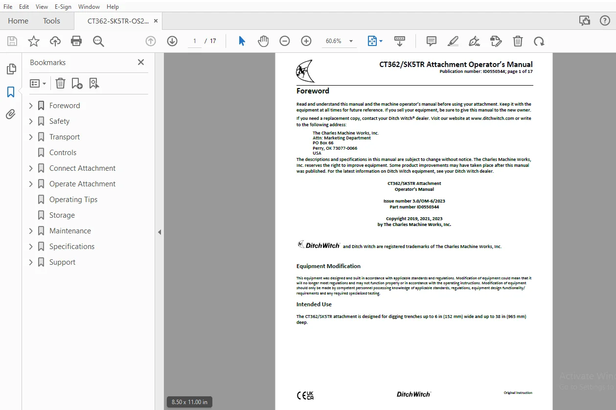
Ditch Witch CT362/SK5TR Attachment Operator’s Manual ID0550344 – PDF DOWNLOAD
FILE DETAILS:
Ditch Witch CT362/SK5TR Attachment Operator’s Manual ID0550344 – PDF DOWNLOAD
Language : English
Pages : 17
Downloadable : Yes
File Type : PDF
IMAGES PREVIEW OF THE MANUAL:
TABLE OF CONTENTS:
Ditch Witch CT362/SK5TR Attachment Operator’s Manual ID0550344 – PDF DOWNLOAD
Foreword............................................................................................................................................. 1
	CT362/SK5TR Attachment Operator’s Manual......................................................................................................... 1
	Issue number 3.0/OM-6/2023 Part number ID0550344................................................................................................. 1
	Copyright 2019, 2021, 2023 by The Charles Machine Works, Inc..................................................................................... 1
		Equipment Modification....................................................................................................................... 1
		Intended Use................................................................................................................................. 1
Safety............................................................................................................................................... 2
	Safety Alert Classifications..................................................................................................................... 2
	Safety Alerts.................................................................................................................................... 3
Transport............................................................................................................................................ 3
	Lift............................................................................................................................................. 3
Controls............................................................................................................................................. 4
Connect Attachment................................................................................................................................... 5
	Attachment....................................................................................................................................... 5
		1. Position attachment on level surface with enough space behind it to accommodate machine................................................... 5
		2. Start engine.............................................................................................................................. 5
		3. Ensure attachment pins are disengaged..................................................................................................... 5
		4. Tilt attachment plate (2) forward......................................................................................................... 5
		5. Position attachment plate in the upper lip of receiver plate (1) on attachment............................................................ 5
		6. Raise lift arms while tilting back attachment plate and engage pins....................................................................... 5
		7. Pins will automatically engage............................................................................................................ 5
		8. Ensure lock pins are engaged by rotating attachment down. Verify that bottoms of lock pins are visible under attachment plate (shown)..... 5
	Hydraulic Hoses.................................................................................................................................. 6
		1. Remove dirt and debris from hydraulic couplers............................................................................................ 6
		2. Connect male coupler on attachment to female coupler (3) on machine....................................................................... 6
		3. Connect female coupler on attachment to male coupler (1) on machine....................................................................... 6
		4. Ensure that connections are secure by pulling on hoses.................................................................................... 6
Operate Attachment................................................................................................................................... 7
	1. Drive machine to starting point............................................................................................................... 7
	2. Stop forward movement and set machine to half throttle........................................................................................ 7
	3. Lower trencher to 1 in (25 mm) above the ground surface....................................................................................... 7
	4. Start forward digging chain rotation. CHAIN WILL MOVE......................................................................................... 7
	5. Increase engine speed to full throttle........................................................................................................ 7
	6. Slowly curl digging boom down to digging depth................................................................................................ 7
	7. Begin moving machine backward................................................................................................................. 7
	8. When finished trenching, stop machine movement and set machine to half throttle............................................................... 7
	9. Curl boom up to top of trench................................................................................................................. 7
	10. Stop digging chain rotation.................................................................................................................. 7
	11. Raise trencher............................................................................................................................... 7
	12. Drive machine away from trench............................................................................................................... 7
	13. Lower attachment to ground surface........................................................................................................... 7
	14. Idle engine a few moments to stabilize engine temperature.................................................................................... 7
	15. Stop engine.................................................................................................................................. 7
Operating Tips....................................................................................................................................... 8
Storage.............................................................................................................................................. 8
Maintenance.......................................................................................................................................... 9
	10-Hour.......................................................................................................................................... 9
		1. Move boom to horizontal position..........................................................................................................10
		2. Measure distance from bottom of boom to chain (A). Chain is correctly tensioned when distance is 1 in (25 mm).............................10
		3. To adjust chain, loosen jam nut on adjustment screw (shown)...............................................................................10
		4. Turn adjustment screw clockwise to tighten chain. Turn screw counterclockwise to loosen chain.............................................10
		5. When proper tension is reached, tighten jam nut...........................................................................................10
		6. Tighten trencher boom clamp bolts to 78 ft-lb (106 N•m)...................................................................................10
		1. Check digging chain tension toward end of boom (3). Tension is correct when 1-1.5 in (25-44 mm) of slide and stop is exposed (4)..........10
		2. To adjust chain, lower boom to ground and stop engine.....................................................................................10
		3. Tighten or loosen adjustment screw (2) and jam nut (1)....................................................................................10
		4. When proper tension is reached, tighten jam nut...........................................................................................10
		1. With boom horizontal, measure distance from bottom of boom to chain. When properly tensioned, distance is 0.5 in (13 mm)..................10
		2. To tighten, pump MPG into cylinder at check valve zerk....................................................................................10
		1. If using rock chain bits, check that bits rotate freely...................................................................................11
		2. Clean chain and check bits after each use.................................................................................................11
		3. Replace bit when carbide cap or insert is worn............................................................................................11
		4. Check pins and bushings for wear by measuring distance between chain pins (3) and comparing it with a new chain...........................11
		5. Check rollers (4) for wear. If roller are worn, replace chain and sprockets...............................................................11
		6. If sidebars (2) are bent or loose on chain pins, use chain spacers to join sidebars.......................................................11
		7. Check teeth (1) for wear..................................................................................................................11
	As Needed........................................................................................................................................11
		1. Start engine and position digging chain with connector pin at top of boom.................................................................11
		2. Lower boom to ground and stop engine......................................................................................................11
		3. Secure chain..............................................................................................................................11
		4. Loop cable through links nearest connector pin (shown)....................................................................................12
		5. Turn tension bolts counterclockwise to release tension on digging chain...................................................................12
		6. Stand clear of chain. Do not stand behind boom and keep feet clear of boom................................................................12
		7. Remove pin from connector pin and drive pin out of link...................................................................................12
		8. Unclamp links (roller boom). Slowly release cable and lower chain to ground...............................................................12
		1. Position digging chain on ground with teeth down and pointed toward machine...............................................................12
		2. Loop cable through end links..............................................................................................................12
		3. Start engine..............................................................................................................................12
		4. Back machine up until digging chain extends past headshaft about 12 in (30 cm)............................................................12
		5. Lower boom to horizontal position and stop engine.........................................................................................12
		6. Secure chain on sprocket booms by locking rear idler sprocket.............................................................................12
		7. Pull rear end of chain over tail sprocket or roller. Pull cable until chain is in place on boom...........................................12
		8. Attach chain jaws to end links and bring links into place.................................................................................12
		9. Install connector pin and lock key........................................................................................................12
		10. Tension chain............................................................................................................................12
Specifications.......................................................................................................................................13
	EU Declaration of Conformity.....................................................................................................................14
	UK Declaration of Conformity.....................................................................................................................15
Support..............................................................................................................................................16
	Procedure........................................................................................................................................16
	Resources........................................................................................................................................16
	Warranty.........................................................................................................................................17
S.S 02/24