Ditch Witch JT1720 Mach 1 Parts Manual 053-079 PDF
$28.95
Ditch Witch JT1720 Mach 1 Parts Manual (053-079) is a detailed guide for precise identification and replacement of components. It ensures efficient maintenance, supporting optimal performance for the specified Ditch Witch JT1720 Mach 1 drilling equipment.
Description
Ditch Witch JT1720 Mach 1 Parts Manual 053-079 – PDF DOWNLOAD
FILE DETAILS:
Ditch Witch JT1720 Mach 1 Parts Manual 053-079 – PDF DOWNLOAD
Language : English
Pages : 247
Downloadable : Yes
File Type : PDF
IMAGES PREVIEW OF THE MANUAL:
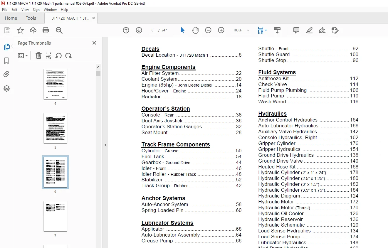
TABLE OF CONTENTS:
Ditch Witch JT1720 Mach 1 Parts Manual 053-079 – PDF DOWNLOAD
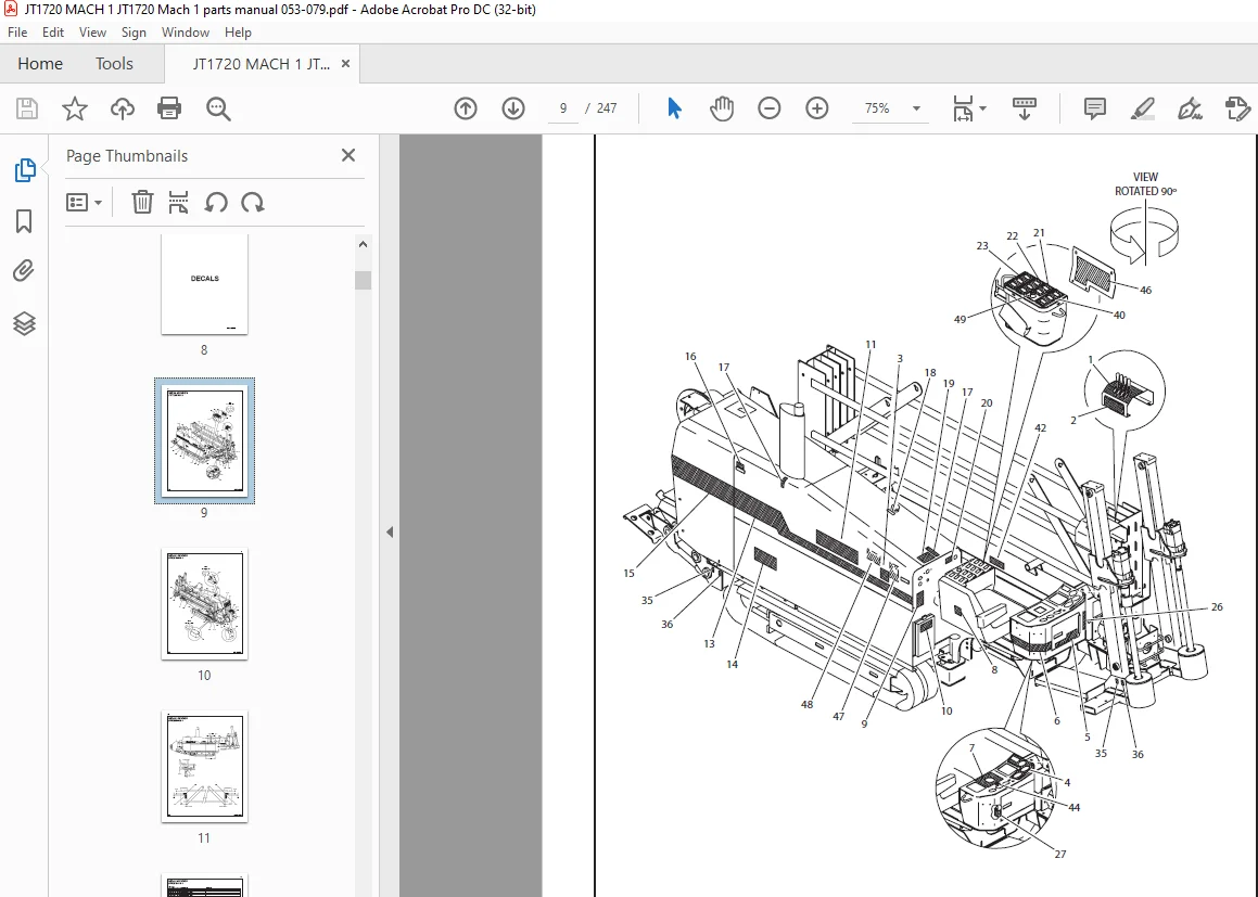
Decals
Decal Location – JT1720 Mach 1 8
Engine Components
Air Filter System 22
Coolant System 20
Engine (85hp) – John Deere Diesel 14
Hood/Cover – Engine 24
Radiator 18
Operator’s Station
Console – Rear 38
Dual Axis Joystick 36
Operator’s Station Gauges 32
Seat Mount 28
Track Frame Components
Cylinder – Grease 50
Fuel Tank 54
Gearbox – Ground Drive 44
Idler – Front 46
Idler Roller – Rubber Track 48
Stabilizer 52
Track Group – Rubber 42
Anchor Systems
Auto-Anchor System 58
Spring Loaded Pin 60
Lubricator Systems
Applicator 68
Auto-Lubricator Assembly 64
Grease Pump 66
Drill Frame Components
Battery Box 80
Carriage 82
Drill Frame 72
Gearbox – Rotation Planetary 86
Gearbox – Thrust Planetary 76
Pivot, Drill Frame 74
Wrench, Backup 84
Wrench, Front 78
Pipe Loader Systems
Pipe Box 98
Pipe Loader – Cover 102
Pipe Loader – Mount 90
Shuttle – Back 94
Shuttle – Front 92
Shuttle Guard 100
Shuttle Stop 96
Fluid Systems
Antifreeze Kit 112
Check Valve 114
Fluid Pump Plumbing 106
Fluid Pump 110
Wash Wand 116
Hydraulics
Anchor Control Hydraulics 164
Auto-Lubricator Hydraulics 166
Auxiliary Valve Hydraulics 142
Console Hydraulics, Right 162
Gripper Cylinder 176
Gripper Hydraulics 154
Ground Drive Hydraulics 138
Ground Drive Valve 140
Heated Hose Kit 168
Hydraulic Cylinder (2” x 1” x 24”) 178
Hydraulic Cylinder (2 5” x 1 25”) 180
Hydraulic Cylinder (3” x 1 5”) 182
Hydraulic Cylinder (3 5” x 1 75”) 184
Hydraulic Diagram 124
Hydraulic Motor 172
Hydraulic Motor (Thrust) 170
Hydraulic Oil Cooler 126
Hydraulic Reservoir 136
Hydraulic Schematic 120
Load Sense Hydraulics 134
Load Sense Pump 174
Lubricator Hydraulics 148
Mud Pump Hydraulics 160
Pipe Loader Hydraulics 146
Rotation Motor Hydraulics 130
Set-up Hydraulics 158
Shuttle Position Hydraulics 156
Thrust Motor Hydraulics 128
Thrust/Rotation Hydraulics 132
Wrench Hydraulics – Backup 152
Wrench Hydraulics – Front 144
Wrench Hydraulics – Upper 150
Electrical
Console Harness 204
Drill Frame Sensor – Front 226
Drill Frame Sensor – Rear 228
Electrical Diagram – Engine/Relay 198
Electrical Diagram – Frame/Engine 196
Electrical Schematic 188
Electrical Strike System 224
Ground Drive Control 230
Hydraulic Filter Harness 210
Pipe Loader Harness 212
Rear Stop Harness 218
Relay Panel Assembly 222
Right Console – Electrical 220
Wrench Switch Harness 216
Accessories
Fluid Mixing Accessories 234
Miscellaneous
Bolt/Nut Torque Chart 238
Filters 242
Optional Kits 242
Parts Manual Change Request 243
Related Publications 242
Replacement O-Ring Chart 241
Warranty Registration 246
Customer Support: [email protected]
S.M