Ditch Witch JT1720 Operator’s Manual 054-520 PDF
$28.95
Description
Ditch Witch JT1720 Operator’s Manual 054-520 – PDF DOWNLOAD
FILE DETAILS:
Ditch Witch JT1720 Operator’s Manual 054-520 – PDF DOWNLOAD
Language : English
Pages : 179
Downloadable : Yes
File Type : PDF
IMAGES PREVIEW OF THE MANUAL:
TABLE OF CONTENTS:
Ditch Witch JT1720 Operator’s Manual 054-520 – PDF DOWNLOAD
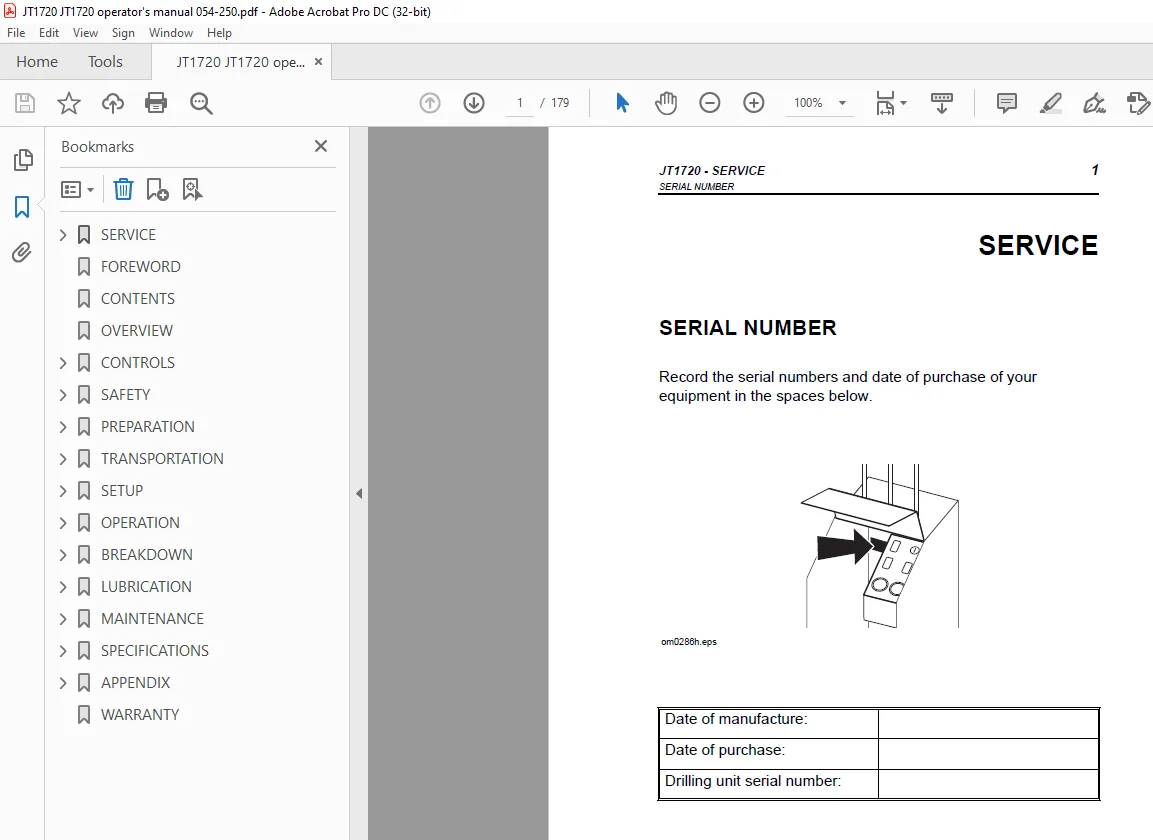
SERVICE 1
SERIAL NUMBER 1
SUPPORT PROCEDURE 2
RESOURCES 2
Publications 2
Ditch Witch Training 2
FOREWORD 3
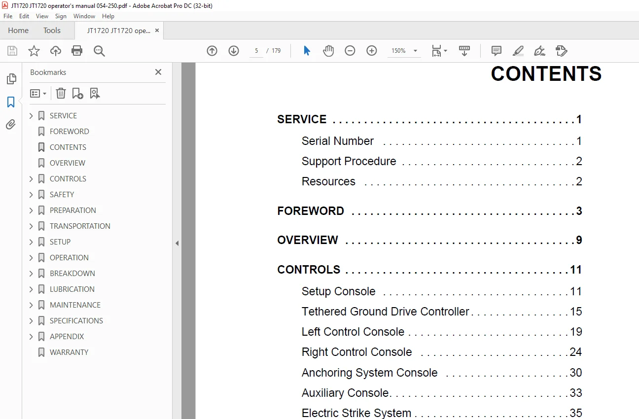
CONTENTS 5
OVERVIEW 9
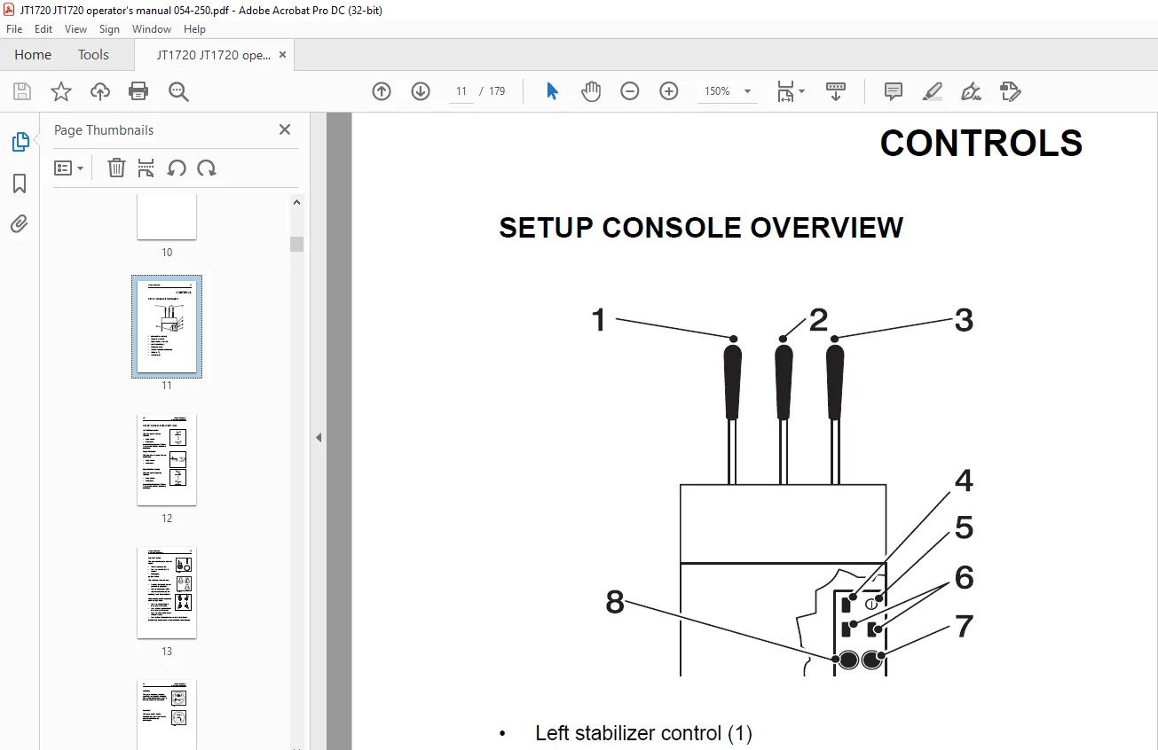
CONTROLS 11
SETUP CONSOLE DESCRIPTIONS 12
TETHERED GROUND DRIVE CONTROLLER OVERVIEW 15
TETHERED GROUND DRIVE CONTROLLER DESCRIPTIONS 16
LEFT CONTROL CONSOLE OVERVIEW 19
LEFT CONTROL CONSOLE DESCRIPTIONS 20
RIGHT CONTROL CONSOLE OVERVIEW 24
RIGHT CONTROL CONSOLE DESCRIPTIONS 25
ANCHORING SYSTEM CONSOLE OVERVIEW 30
ANCHORING SYSTEM CONSOLE DESCRIPTIONS 31
AUXILIARY CONSOLE OVERVIEW 33
AUXILIARY CONSOLE DESCRIPTIONS 34
Battery Disconnect Switch 34
ESID OVERVIEW 35
ESID DESCRIPTIONS 36
SUBSITE 750 DISPLAY OVERVIEW 38
SUBSITE 750D DISPLAY DESCRIPTIONS 39
SAFETY 45
ACCESSORIES 46
Fire Extinguisher 46
Lighting Kit 46
UNDERGROUND HAZARDS 46
EMERGENCY PROCEDURES 47
Electric Strike Description 47
If an Electric Line is Damaged 48
If an Electric Line is Damaged 49
If a Gas Line is Damaged 50
If a Fiber Optic Cable is Damaged 50
If Machine Catches on Fire 50
JOBSITE CLASSIFICATION 51
Inspecting Jobsite 51
Selecting a Classification 52
Applying Precautions 53
SAFETY ALERT CLASSIFICATIONS 55
SAFETY ALERTS 56
PREPARATION 61
GATHER INFORMATION 61
Job Plan 61
One-Call Services 61
Pullback Material 61
Traffic Control 61
Emergency Services 61
INSPECT SITE 62
Identify Hazards 63
Select Start and End Points 64
PLAN BORE PATH 65
Recommended Bend Limit 66
Entry Pitch 67
Minimum Setback 68
Minimum Depth 69
CHECK SUPPLIES AND PREPARE EQUIPMENT 70
Check Supplies: 70
Prepare Equipment 71
PREPARE JOBSITE 72
Mark Bore Path 72
Entry Point 73
RECORD BORE PATH 74
TRANSPORTATION 75
LIFT 75
TIEDOWN 76
Points 76
Procedure 76
OPERATE TETHERED GROUND DRIVE CONTROLLER 77
HAUL 78
Loading onto Trailer 78
Unloading from Trailer 79
TOW 80
SETUP 83
UNLOAD 83
Position Drilling Unit and Frame 83
ASSEMBLE ELECTRIC STRIKE SYSTEM 84
FCC Statement 84
Assemble Bonding Equipment 85
Test Control Box 85
ANCHOR 86
ASSEMBLE DRILL HEAD 87
ATTACH EZ-CONNECT TO DRILL HEAD 88
ATTACH TRANSITION SUB 90
CONNECT DRILL PIPE 91
ENGAGE EZ-CONNECT 92
OPERATION 93
START SYSTEM 93
OPERATE THRUST/ROTATION CONTROL 94
DRILL FIRST PIPE 96
Break Joint at Saver Sub 97
ADD PIPE 98
Option A: Use Manual Pipeloader Controls 98
Option B: Use Autoload Function 100
REMOVE/ADD PIPE BOX 102
Prepare 102
Remove 103
Load 103
CORRECT DIRECTION 104
SURFACE DRILL HEAD 106
PULLBACK AND BACKREAMING 107
Attaching EZ-Connect to Backreamer 107
Connecting Pullback Device 110
Backreaming 111
Removing Pipe 116
Removing Pullback Device 121
Automation Troubleshooting Tips 122
BREAKDOWN 123
REMOVE ANCHORS 123
RINSE EQUIPMENT 124
DISCONNECT 124
STOW TOOLS 124
LUBRICATION 125
OVERVIEW 126
ENGINE OIL 127
Check 127
Change 127
FRAME 128
Water Swivel 129
Pipe Guide Bearings 129
Thrust Chain 129
Thrust Chain Flange Bearing 129
Carriage Slide Bracket 130
Pipe Loader Shuttle Slide 130
Pipe Auto Lubricator 131
GEARBOXES 134
Rotation Gearbox 135
Carriage Travel Gearbox 135
Ground Drive Gearbox 135
HYDRAULIC OIL 136
Check 136
Change 136
FLUID PUMP 137
Check 137
Change 137
MAINTENANCE 139
OVERVIEW 139
GENERAL COMPONENTS 140
Inspect Hoses 140
Pipe Loader 141
Batteries 141
Alternator Belt 142
Radiator 142
Saver Sub 144
FILTERS 145
Drilling Fluid Pump Y- Strainer 145
Fuel Filter 146
Air Filter 146
Muffler 146
POWER COMPONENTS 147
Track Tension 147
Thrust Chain Tension 148
PIPE LOADER AUTOMATION 149
Proximity Switches 149
PIPE 152
TROUBLESHOOT STRIKE SYSTEM 153
USE ELECTRIC STRIKE SIMULATOR 156
Current Test 156
Voltage Test 157
SPECIFICATIONS 159
DRILLING UNIT 159
APPENDIX 163
A BEND LIMITS 163
B ENTRY PITCH, SETBACK, AND DEPTH 166
C DRILLING FLUID REQUIREMENTS 167
D NOZZLE FLOW 170
WARRANTY 173
Need help? Contact: [email protected]
S.V