Ditch Witch JT20 / JT20XP Parts Manual 053-2628 PDF
$30.95
Description
Ditch Witch JT20 / JT20XP Deutz® TD2.9, Deutz TD2.9L4 Parts Manual 053-2628 (Vol 1 – Vol 3) – PDF DOWNLOAD
FILE DETAILS:
Ditch Witch JT20 / JT20XP Deutz® TD2.9, Deutz TD2.9L4 Parts Manual 053-2628 – PDF DOWNLOAD
Language : English
Pages : 565
Downloadable : Yes
File Type : PDF
IMAGES PREVIEW OF THE MANUAL:
TABLE OF CONTENTS:
Ditch Witch JT20 / JT20XP Deutz® TD2.9, Deutz TD2.9L4 Parts Manual 053-2628 – PDF DOWNLOAD
Volume 1
Decals
Decal Location – JT20 18
Decal Location – JT20/JT20XP 14, 16
Decal Location – JT20 Stage V 10, 12
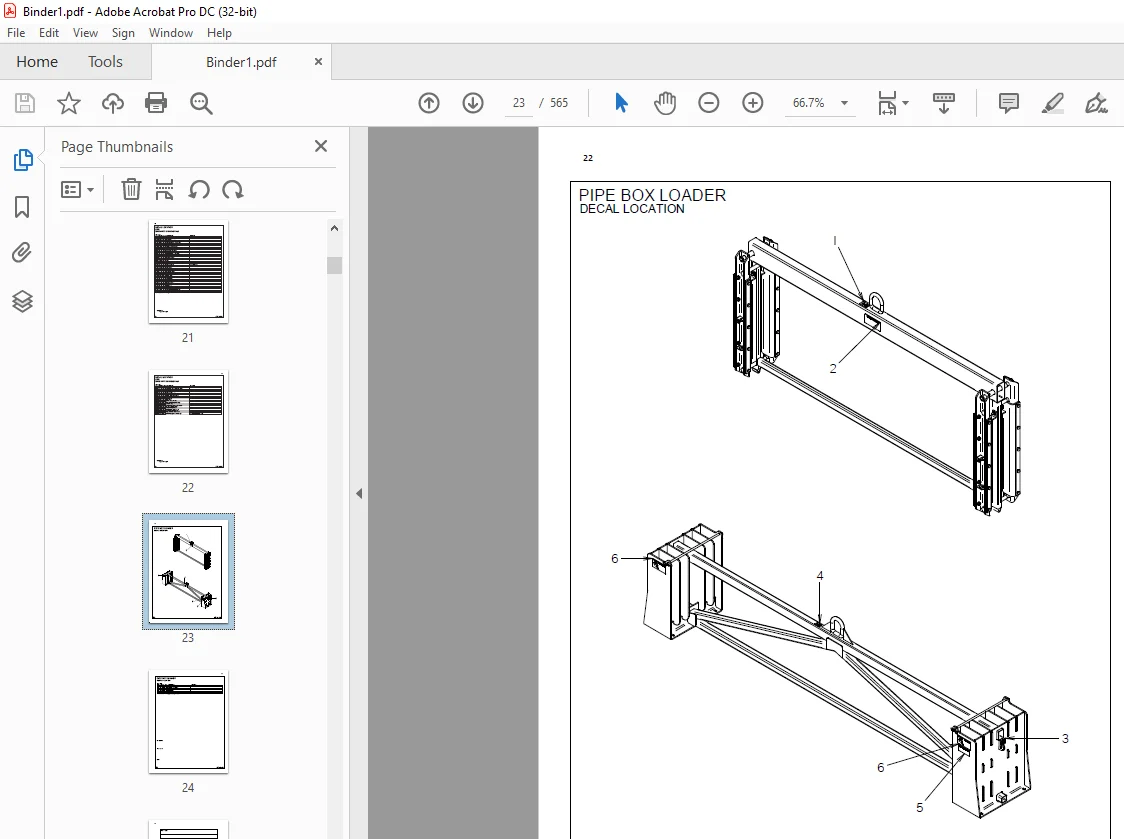
Decal Location – Pipe Box Loader 22
Engine Components
Battery 80, 82, 84
Controls, Rear 86
Cooling System – Cooler Mounting 32, 34
Cooling System – Fan Assembly 42, 44
Cooling System – Radiator Plumbing 36, 38, 40
Electrical Mounting 68, 70, 72
Engine Mounts 30
Engine Service Parts 28
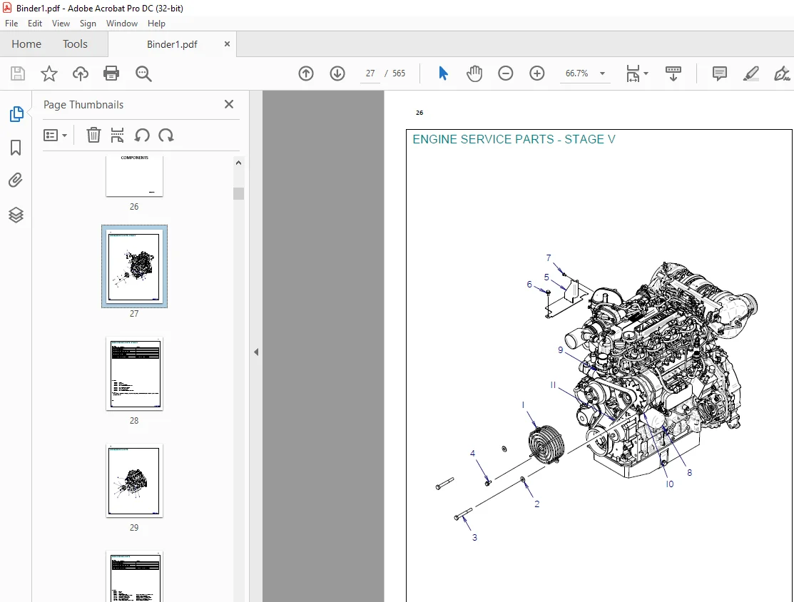
Engine Service Parts – Stage V 26
Engine Skid 74, 76, 78
Exhaust System 46, 48, 50
Exhaust System – LRC 52, 54
Exhaust System (ROW) 50, 52
Fuel System 62, 64, 66
Hood, Front Fixed 92, 94
Hood, Front Opening 96, 98
Hood, Rear Fixed 100
Hood, Rear Opening 102
Hood Support, Front 88, 90
Intake System 56, 58, 60
Frame Components
Carriage 106, 108, 110
Carriage Spindle 112, 114
Frame Tilt 150
Fuel Cooler 136, 138
Fuel Tank 132, 134
Gearbox – Ground Drive 142
Grease Cylinder 146
Ground Drive Tracks 140
Idler, Front 144
Pinion Drive Assembly 124
Pipe Guide 126
Proximity Switches 152
Proximity Switches – Drill Pipe 154
Rotation Gear Box 122
Saverlok Tool 116
Stabilizer 148
Thrust Drive 118, 120
Wrench, Rotating 128
Wrench, Stationary 130
Operator’s Station
Console, Left 164, 166
Console, Right 174
Electrical Strike System 176, 178
ESID Module and Gauge Panel 168, 170
Ground Drive Control 180
Operator Seat 160, 162
Operator Station Floor 158
Remote Control 182
Vandal Cover 172
Volume 2
Hydraulics
Auxiliary 248, 250, 252
Carve POR 234
Cylinder – 2 0” x 1 0” 302
Cylinder – 3 0” x 1 5” 304
Cylinder – 3 5” x 1 75” 306
Cylinder – 4 0” x 2 0” x 2 0” 308
Drilling Fluid Motor 258, 260, 262
Dual Slide Anchor Cylinder 238, 240
Dual Slide/Long Anchor Rotation 242
Fan Drive 254, 256
Filter and Reservoir 208, 210
Frame Tilt 296
Gauge/Test Ports 232
Ground Drive 236
Lubricator 244, 246
Oil Cooler Plumbing 212, 214
Pilot Valves 222, 224
Pipe Box Shift 292, 294
Pipe Grip 278
Pipe Lift 290
Pipe Lift w/ Flow Divider 286, 288
Pump/Selector 218
Pump Stack Mounting 194, 196
Pump Stack Supply 198, 200
Return 202, 204, 206
Rotation 216
Schematic 186, 190
Selector 220
Shuttle 280, 282, 284
Stabilizer 298
Thrust 226, 228
Thrust – Brake 230, 272, 274
Valve Parts 300
Wrench, Rotating 264, 266
Wrench, Stationary 268, 270
Wrench Relief 276
Anchor System
Anchor Valve/Lubricator Mount 316, 314
Auto-Luber Assembly 322
Dual Slide Anchors 312
Grease Pump 320
Lubricator Pump 318
Fluid System
Drilling Fluid Plumbing 326, 334
Drilling Fluid Pump Plumbing 328
Drilling Fluid Transfer 336
Mud Pump 332
Pipe Loader System
Covers 358
Lifters 340, 342
Pipe Box 360
Pipe Loader Valve/Covers 354, 356
Shuttle 344
Shuttle Guard 350, 352
Shuttle Mount 346, 348
Volume 3
Electrical
Diagram – Alternator Power Cable 484
Diagram – Batt Cable 476, 478, 480, 526, 528
Diagram – Carriage Harness 456
Diagram – Console Harness, Left 458, 462
Diagram – Console Harness, R 450, 452, 454
Diagram – Engine Harness 420, 424
Diagram – Frame Harness, Rear 470
Diagram – Frame Harness, Stage V 400, 406
Diagram – Frame/Relay Harness 428, 438
Diagram – Glow Plug Cable 508
Diagram – Glow Plug Fuse Cable 468
Diagram – Grid Heater Cable 466
Diagram – Ground Cable 482, 504
Diagram – Ground Cable BLK 486
Diagram – Ground Strap, Braided 506
Diagram – Hose Track Harness 448
Diagram – Pipeloader Harness 488, 492, 496
Diagram – Primary Cable 500, 502
Diagram – Relay/Frame Harness 510, 520
Diagram – Sensor Jumper 474
Diagram – Starter Harness 530
Schematic 364, 376, 388
Accessories
Antifreeze Tank 534
Canopy 538
GPS Kit – CLM3000 542, 544
Pipe Box Loader 548
Softcab 540
Telematics Kit – CLM3000 542
Tie Down Kit – T18B 546
Transport Pipe Box 550
Umbrella Kit 536
Miscellaneous
Filters 560
Optional Kits 560
Related Publications 560
Replacement O-Ring Chart 559
Torque Information 554
Warranty Registration 562
Customer Support: [email protected]
https://vimeo.com/902458718?share=copy
S.V