Ditch Witch JT25 Cummins QSB4.5 Parts Manual Vol1&3
$27.95
Ditch Witch JT25 Cummins QSB4.5 Parts Manual Vol1&3 – PDF DOWNLOAD
Description
Ditch Witch JT25 Cummins QSB4.5 Parts Manual Vol1&3 – PDF DOWNLOAD
FILE DETAILS:
Ditch Witch JT25 Cummins QSB4.5 Parts Manual Vol1&3 – PDF DOWNLOAD
Language : English
Pages :477
Downloadable : Yes
File Type : PDF
TABLE OF CONTENTS:
Ditch Witch JT25 Cummins QSB4.5 Parts Manual Vol1&3 – PDF DOWNLOAD
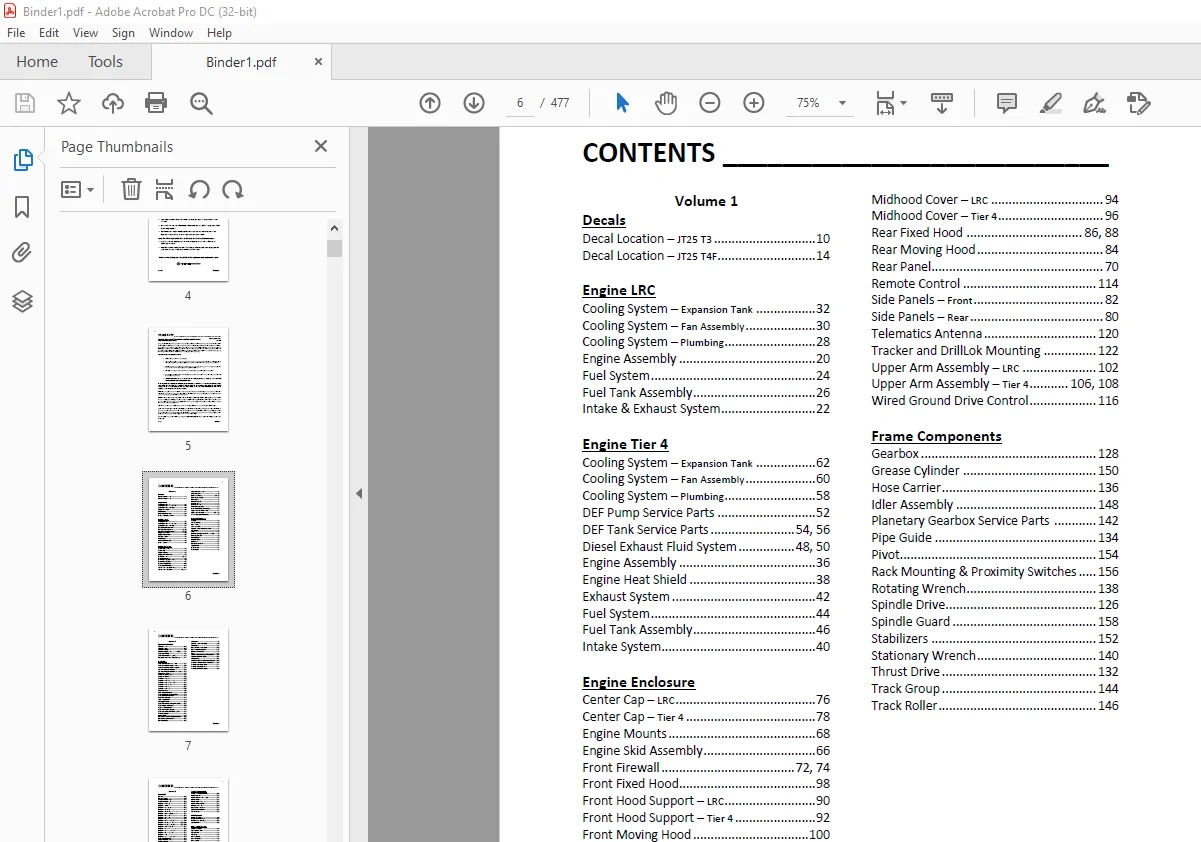
Decals
Decal Location – JT25 T3 10
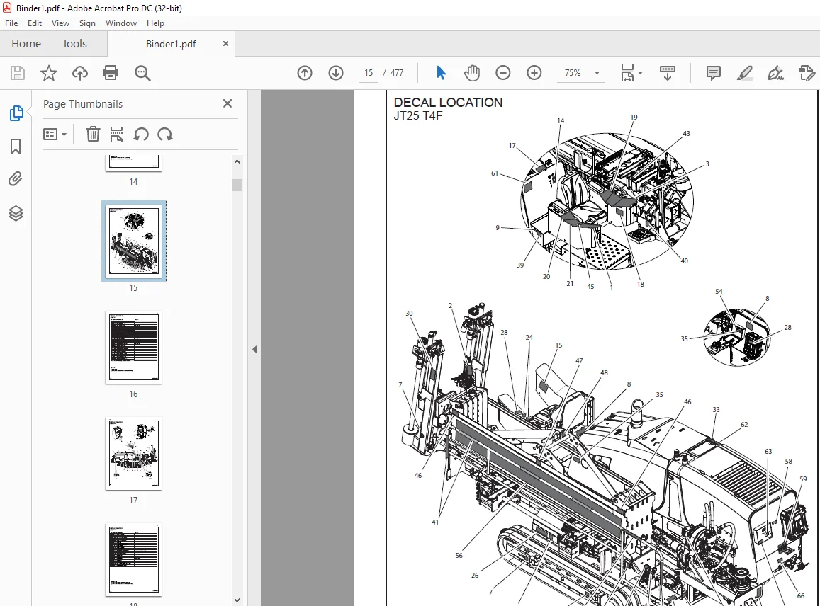
Decal Location – JT25 T4F 14
Engine LRC
Cooling System – Expansion Tank 32
Cooling System – Fan Assembly 30
Cooling System – Plumbing 28
Engine Assembly 20
Fuel System 24
Fuel Tank Assembly 26
Intake & Exhaust System 22
Engine Tier 4
Cooling System – Expansion Tank 62
Cooling System – Fan Assembly 60
Cooling System – Plumbing 58
DEF Pump Service Parts 52
DEF Tank Service Parts 54, 56
Diesel Exhaust Fluid System 48, 50
Engine Assembly 36
Engine Heat Shield 38
Exhaust System 42
Fuel System 44
Fuel Tank Assembly 46
Intake System 40
Engine Enclosure
Center Cap – LRC 76
Center Cap – Tier 4 78
Engine Mounts 68
Engine Skid Assembly 66
Front Firewall 72, 74
Front Fixed Hood 98
Front Hood Support – LRC 90
Front Hood Support – Tier 4 92
Front Moving Hood 100
Ground Drive Control 118
Lower Arm Assembly – LRC 104
Lower Arm Assembly – Tier 4 110, 112
Midhood Cover – LRC 94
Midhood Cover – Tier 4 96
Rear Fixed Hood 86, 88
Rear Moving Hood 84
Rear Panel 70
Remote Control 114
Side Panels – Front 82
Side Panels – Rear 80
Telematics Antenna 120
Tracker and DrillLok Mounting 122
Upper Arm Assembly – LRC 102
Upper Arm Assembly – Tier 4 106, 108
Wired Ground Drive Control 116
Frame Components
Gearbox 128
Grease Cylinder 150
Hose Carrier 136
Idler Assembly 148
Planetary Gearbox Service Parts 142
Pipe Guide 134
Pivot 154
Rack Mounting & Proximity Switches 156
Rotating Wrench 138
Spindle Drive 126
Spindle Guard 158
Stabilizers 152
Stationary Wrench 140
Thrust Drive 132
Track Group 144
Track Roller 146
5
CONTENTS __________________________
ID0383503
Volume 2
Operator’s Station
Console – Left 166
Console – Right 168
Console Gauges 170
Console Gauges – Dual Joystick Option 172
Operator Station 162
Operator Station – Cab Option 164
Rotation, Thrust and Fluid Gauges 174
Hydraulics
Anchor Hydraulics – Heavy Duty 234
Anchor Valve Hydraulics – Left Side 230
Anchor Valve Hydraulics – Right Side 232
Auxiliary Pump Hydraulics 236
Auxiliary Pump Hydraulics – With Cab 238
Control Assembly 192
Cooler and Tank – LRC 184
Cooler and Tank – Tier 4 186
Cylinder – 20” x 10” 260
Cylinder – 20” x 10” x 240” 262
Cylinder – 20” x 125” x 4025” 264
Cylinder – 25” x 125” 266
Cylinder – 30” x 15” 268
Cylinder – 40” x 20” 270
Filter Manifold 190
Fluid Pump Hydraulics 220
Ground Drive Brake Hydraulics 216
Ground Drive Hydraulics 214
Hose Carrier Hoses 212
Load Sense Pump 218
Oil Supply Circuit 188
Operators Station Swing Hydraulics 258
Pipe Gripper Hydraulics 250
Pipe Lifter Hydraulics 254
Pipe Loader Valve Supply 246
Pipe Loader/Wrench Valve Drain 248
Pivot Hydraulics 242
Pump Stack 194
Rotation Motor Flushing Hydraulics 200
Rotation Motor Hydraulics 198
Rotation Pump 196
Schematic 178
Selector Valve Hydraulics 210
Setup Valve 240
Shuttle Motor Hydraulics 256
Shuttle Stop Hydraulics 252
Stabilizer Hydraulics 244
Tank 182
Thrust & Rotation Motor Case Drain 208
Thrust Motor Hydraulics 204
Thrust Pump 202
Thrust Two Speed & Brake Hydraulics 206
Wrench & Anchor Valve Hydraulics 226
Wrench Hydraulics, Front 222
Wrench Hydraulics, Rear 224
Wrench Rotate Hydraulics 228
6
CONTENTS __________________________
ID0383503
Volume 3
Electrical
Battery 288
Battery Cables 290
Cooler Harness – LRC 314
Cooler Harness – Tier 4 308
Diagram – Cab Harness 372
Diagram – Cables 324
Diagram – Carriage Harness 368
Diagram – Cooler Harness 310
Diagram – Cooler Harness Tier 3 316
Diagram – DOC and SCR Harness 322
Diagram – Engine Harness 302
Diagram – Engine Harness Tier 3 300
Diagram – Frame Harness 336
Diagram – Hose Track Harness 370
Diagram – Op Station Left Harness 346, 350
Diagram – Op Station Right Harness 354, 360
Diagram – Pipe Loader Harness 364
Diagram – Power Harness, Cab 376
Diagram – Rear Frame Harness 332
Diagram – Seat Jumper Harness 374
Diagram – Tether 328
Diagram – Wireless Ground Drive 326
DOC and SCR Harness 320
Engine Harness – LRC 296
Engine Harness – Tier 4 298
Firewall Electrical 292
Mounting Center 294
Rear Frame Harness 330
Schematic 274
Anchor Components
2 Gallon Thread Lubricator 388
Anchor System 382
Anchor System – Heavy Duty 384
Anchor Valve 394
Anchor Valve – Heavy Duty 396
Anchor Valve Mount 380
Anchors – Heavy Duty 386
Auto-Luber Assembly 390
Electrical Strike System 398
Grease Pump 392
Fluid Systems
Antifreeze Tank 410
Fluid Pump Assembly 402
Fluid System, Carriage 408
Service Parts 406
Pipe Loader Systems
Gripper Cylinder 426
Pipe Loader Lifter 414
Pipe Shuttle 424
Pipe Stop 416
Shuttle Guard 422
Shuttle Mounts 418
Shuttle Stop 420
Valve Mount and Cover 428
IMAGES PREVIEW OF THE MANUAL:
Questions? Email us: [email protected]
S.M 08/24