Ditch Witch JT25 Tier 3 & JT25 Tier 4i Parts Manual 053-2437 PDF
$29.95
Description
Ditch Witch JT25 Tier 3 & JT25 Tier 4i Parts Manual 053-2437 – PDF DOWNLOAD
FILE DETAILS:
Ditch Witch JT25 Tier 3 & JT25 Tier 4i Parts Manual 053-2437 – PDF DOWNLOAD
Language : English
Pages : 410
Downloadable : Yes
File Type : PDF
IMAGES PREVIEW OF THE MANUAL:
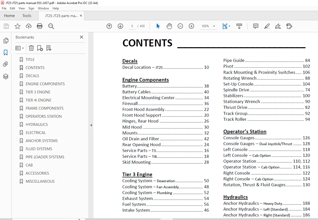
TABLE OF CONTENTS:
Ditch Witch JT25 Tier 3 & JT25 Tier 4i Parts Manual 053-2437 – PDF DOWNLOAD
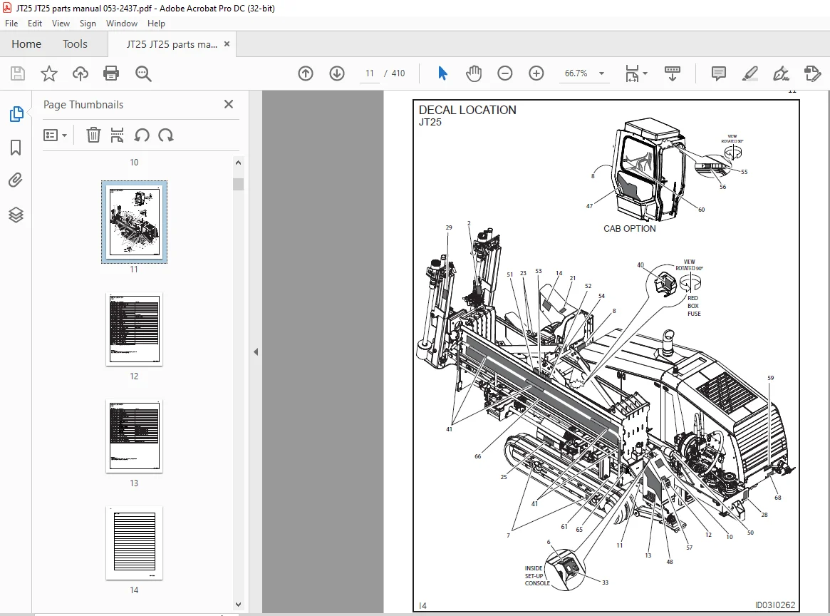
Decals
Decal Location – JT25 10
Engine Components
Battery 38
Battery Cables 40
Electrical Mounting Center 34
Firewall 36
Front Hood Assembly 22
Front Hood Support 20
Hinges, Rear Hood 26
Mid Hood 30
Mounts 32
Oil Drain and Filter 42
Rear Opening Hood 24
Service Parts – T3 16
Service Parts – T4i 18
Skid Mounting 28
Tier 3 Engine
Cooling System – Deaeration 50
Cooling System – Fan Assembly 48
Cooling System – Plumbing 52
Exhaust System 54
Fuel System 56
Intake System 46
Tier 4i Engine
Cooling System – Deaeration 64
Cooling System – Fan Assembly 62
Cooling System – Plumbing 66
Exhaust System 68
Fuel System 70
Intake System 60
Frame Components
Fuel Tank Assembly 76
Gearbox 78
Grease Cylinder 98
Hose Carrier 86
Idler Assembly 96
Pipe Guide 84
Pivot 102
Rack Mounting & Proximity Switches 106
Rotating Wrench 88
Set-Up Console 104
Spindle Drive 74
Stabilizers 100
Stationary Wrench 90
Thrust Drive 82
Track Group 92
Track Roller 94
Operator’s Station
Console Gauges 126
Console Gauges – Dual Joystick/Thrust 128
Left Console 118
Left Console – Cab Option 120
Operator Station 110, 112
Operator Station – Cab Option 114, 116
Right Console 122
Right Console – Cab Option 124
Rotation, Thrust & Fluid Gauges 130
Hydraulics
Anchor Hydraulics – Heavy Duty 188
Anchor Hydraulics – Left (Standard) 184
Anchor Hydraulics – Right (Standard) 186
Auxiliary Pump Hyd 190
Auxiliary Pump Hyd – Cab Option 192
Cylinders – 2 0” x 1 0” 214
Cylinders – 2 0” x 1 0” x 24” 216
Cylinders – 2 0” x 1 25” x 40 25” 218
Cylinders – 2 5” x 1 25” 220
Cylinders – 3 0” x 1 5” 222
Cylinders – 4 0” x 2 0” 224
Filter & Reservoir Hydraulics 138
Fluid Pump Hydraulics 174
Front Wrench Hydraulics 176
Ground Drive Brake Hydraulics 170
Ground Drive Hydraulics 168
Hose Carrier Hoses 166
5
CONTENTS _______________________
ID0290322
Load Sense Pump Hydraulics 172
Oil Cooler 142
Operator’s Station Swing Hydraulics 212
Pipe Gripper Hydraulics 204
Pipe Lifter Hydraulics 208
Pipe Loader Valve Supply 200
Pipe Loader/Wrench Valve Drain 202
Pivot Hydraulics 196
Pump Mount 144
Pump Stack POR Flush & Charge Hyd 148
Pump Stack Suction 146
Rear Wrench Hydraulics 178
Reservoir 140
Rotation Motor Flushing Hydraulics 154
Rotation Motor Hydraulics 152
Rotation Pump Hydraulics 150
Schematic 134
Selector Valve Hydraulics 164
Setup Valve 194
Shuttle Motor Hydraulics 210
Shuttle Stop Hydraulics 206
Stabilizer Hydraulics 198
Thrust & Rotation Motor Case Drain 162
Thrust Motor Hydraulics 158
Thrust Pump Hydraulics 156
Thrust Two-Speed & Brake Hyd 160
Wrench & Anchor Valve Hydraulics 180
Wrench Rotate Hydraulics 182
Electrical
Diagram – Battery Cables 320
Diagram – Cab Harness 318
Diagram – Cables 324
Diagram – Carriage Harness 308
Diagram – Drill Fluid Harness 278
Diagram – Engine Harness 240, 242
Diagram – Frame Harness 250, 280, 290
Diagram – Frame Harness, Rear 248, 298
Diagram – Ground Cables 326
Diagram – Hose Track Harness 306
Diagram – Op Station Left 258
Diagram – Op Station Right 262, 268, 274
Diagram – Pipe Loader 300, 304
Diagram – Power Cables 322
Diagram – Power Harness, Cab 316
Diagram – Rear Frame 248
Diagram – Remote Display 312
Diagram – Seat Jumper Harness 310
Diagram – Setup Box Harness 244
Diagram – Work Light Harness 314
Schematic 228
Anchor Systems
2-Gallon Thread Lubricator 338
Anchor System – Heavy Duty 334
Anchor System – Standard 332
Anchor Valve Mount 330
Anchors – Heavy Duty 336
Auto-Luber Assembly 340
Grease Pump 342
Fluid System
Antifreeze Tank 352
Fluid Pump Assembly 346
Fluid System, Carriage 350
Service Parts 348
Pipe Loader System
Gripper Cylinder 368
Pipe Loader Lifter 356
Pipe Shuttle 366
Pipe Stop 358
Shuttle Guard 364
Shuttle Mounts 360
Shuttle Stop 362
Valve Mount & Cover 370
Cab
A/C Plumbing 380
Cab 374
Cab Door 376
Cab Electric 382
Cab Foot Box 378
Heater Hose 384
Accessories
Drilling Fluid Transfer 396
Grounding Hardware 398
Lights 390
Pipe Box 388
Umbrella 392
Wash Wand 394
Miscellaneous
Filters 408
Optional Kits 408
Torque Information 402
Related Publications 408
Replacement O-Ring Chart 407
Warranty Registration 410
Need help? Contact: [email protected]
S.V