Ditch Witch JT25 Tier 4 & LRC (Tier 3) Operator’s Manual 053-2836 PDF
$28.95
Description
Ditch Witch JT25 Tier 4 & LRC (Tier 3) Operator’s Manual 053-2836 – PDF DOWNLOAD
FILE DETAILS:
Ditch Witch JT25 Tier 4 & LRC (Tier 3) Operator’s Manual 053-2836 – PDF DOWNLOAD
Language : English
Pages : 240
Downloadable : Yes
File Type : PDF
IMAGES PREVIEW OF THE MANUAL:
TABLE OF CONTENTS:
Ditch Witch JT25 Tier 4 & LRC (Tier 3) Operator’s Manual 053-2836 – PDF DOWNLOAD
Overview 2
Serial Number Location 3
Intended Use 4
Equipment Modification 4
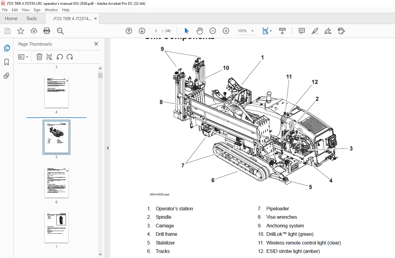
Unit Components 5
FCC Statement – Internal Transmitter 6
RF Exposure Statement 6
Operator Orientation 7
About This Manual 7
Bulleted Lists 7
Numbered Lists 7
Foreword 8
Contents 10
Safety 12
Guidelines 13
California Proposition 65 Warning 13
Emergency Procedures 14
Electric Strike Description 14
If an Electric Line is Damaged 15
If a Gas Line is Damaged 16
If a Fiber Optic Cable is Damaged 17
If Machine Catches on Fire 17
Safety Alert Classifications 18
Machine Safety Alerts 19
Controls 22
Set-Up Console 23
Tethered Ground Drive Controller 27
Wireless Ground Drive Controller 29
Left Control Console 32
Display 32
Traditional Controls 38
Alternate Controls 42
Right Control Console 46
Lights 46
Traditional Controls 49
Alternate Controls 52
Anchoring System Console 56
Seat 58
Cab Controls (optional) 59
Top/Rear 59
Front 61
Engine Compartment Controls 63
Miscellaneous Controls 65
Operation Overview 66
Planning 67
Setting Up at Jobsite 67
Drilling 68
Backreaming 69
Backreaming Tips 69
Leaving Jobsite 69
Storing Equipment 69
Prepare 70
Gather Information 72
Review Job Plan 72
Notify One-Call Services 72
Examine Pullback Material 72
Arrange for Traffic Control 72
Plan for Emergency Services 72
Inspect Site 73
Identify Hazards 73
Select Start and End Points 74
Classify Jobsite 75
Select a Classification 75
Apply Precautions 76
Plan Bore Path 77
Recommended Bend Limits 78
Entry Pitch 80
Minimum Setback 81
Minimum Depth 81
Bore Path Calculator 82
Prepare Jobsite 84
Mark Bore Path 84
Prepare Entry Point 84
Check Supplies and Prepare Equipment 85
Check Supplies 85
Prepare Equipment 86
Assemble Accessories 87
Drive 88
Start Unit 89
Steer Unit 89
Tips to Reduce Track Wear 89
Safe Slope Operation 90
Shut Down Unit 91
Transport 92
Lift 93
Pipe Box Lifting Procedure 93
Load 93
Tie Down 94
Unload 95
Retrieve 95
Conduct a Bore 98
Position Equipment 100
Connect Fluid System 100
Start System 101
Prime Drilling Fluid Pump 101
Operate Carriage Control 102
Drilling (Traditional Controls) 102
Drilling (Alternate Controls) 102
Coordinated Makeup 102
Clamp Pipe 103
Assemble Drill String 104
Connect Drill Pipe 105
Drill First Pipe 106
Enable Automated Pipeloader System 106
Add Pipe 107
Correct Direction 109
Basic Rules 109
Procedure 110
Drill Head Position 110
Use AutoCarve 111
Operation 112
Record Bore Path 113
Surface Drill Head 114
Backream 115
Remove Pipe 117
Remove Pullback Device 119
Systems and Equipment 120
Anchor System 122
Select Anchor 122
Drive Anchors (Rock) 123
Drive Anchors (Dirt) 123
Remove Anchors 123
Electric Strike System 124
FCC Statement 124
Assemble Voltage Detector 125
Test Strike System 125
Troubleshoot Strike System 126
Use Electric Strike Simulator 128
Drilling Fluid 130
Guidelines 130
Polymer 130
Bentonite 131
Mixtures 131
Drilling Fluid Requirements 133
Funnel Viscosity 133
DrillLok™ 134
Overview 134
Downhole Tools 135
Nozzles 135
Bits 135
Beacon Housings 136
Backreamers 137
Backream Fluid Requirements 138
Quick Wrench 140
Drill Pipe 142
Perform Regular Drill Pipe Care 142
Use Drill Pipe Correctly 143
Pipe Boxes 145
Remove/Install Pipe Box 145
Add/Remove Single Pipe 147
Wireless Ground Drive Controller 151
Before each use 151
Operation 152
Troubleshooting 153
Cruise Control 154
Engage 154
Adjust Settings 155
Override 155
Disengage 155
Resume 155
Diagnostic Codes 156
Electronic Controlled Engine Overview 156
Reading Engine Diagnostic Codes 156
Engine Diagnostic Codes 156
Reading Machine Diagnostic Codes 157
Machine Diagnostic Codes 158
Complete the Job 166
Antifreeze Drilling Unit 167
Add Antifreeze 167
Reclaim Antifreeze 168
Rinse Equipment 169
Using Washwand 169
Disconnect 170
Stow Tools 170
Service 172
Service Precautions 173
Welding Precaution 173
Washing Precaution 173
Working Under Drilling Unit 174
Opening/Closing Engine Enclosure 175
Recommended Lubricants/Service Key 176
Approved Coolant 177
Approved Fuel 178
Diesel Exhaust Fluid (DEF) – Tier 4 Only 179
Startup/10 Hour 181
Drilling Unit 182
50 Hour 189
Drilling Unit 189
250 Hour 193
Drilling Unit 193
500 Hour 195
Drilling Unit 195
1000 Hour 197
Drilling Unit 197
2000 Hour 201
Drilling Unit 201
4500 Hour 203
As Needed 204
Drilling Unit 205
Specifications 214
Support 220
Procedure 220
Resources 220
Publications 220
Ditch Witch Training 220
Warranty 221
Service Record 224
Appendix 226
Customer Support: [email protected]
https://vimeo.com/902493465?share=copy
S.V