Operator Manual for Ditch Witch JT32 / AT32 Cummins 4.5 053-3298 PDF
$28.95
Description
Ditch Witch JT32 / AT32 Cummins® 4.5 Operator’s Manual 053-3298 – PDF DOWNLOAD
FILE DETAILS:
Ditch Witch JT32 / AT32 Cummins® 4.5 Operator’s Manual 053-3298 – PDF DOWNLOAD
Language : English
Pages : 215
Downloadable : Yes
File Type : PDF
IMAGES PREVIEW OF THE MANUAL:
TABLE OF CONTENTS:
Ditch Witch JT32 / AT32 Cummins® 4.5 Operator’s Manual 053-3298 – PDF DOWNLOAD
Overview 2
California Proposition 65 2
Serial Number Location 3
Intended Use 4
Equipment Modification 4
Machine Components 5
Regulatory Notices 6
United States 6
Canada 6
RF Exposure Statement 7
Operator Orientation 7
Operating Area 7
About This Manual 8
Bulleted Lists 8
Numbered Lists 8
Foreword 10
Contents 12
Overview 12
1 12
Foreword 12
9 12
Safety 12
13 12
Prepare 12
23 12
Controls 12
45 12
Drive 12
85 12
Transport 12
91 12
Conduct a Bore 12
97 12
Systems and Equipment 12
121 12
Complete the Job 12
159 12
Maintenance 13
163 13
Specifications 13
203 13
Support 13
213 13
Safety 14
Safety Alert Classifications 15
Guidelines 16
Emergency Procedures 17
Electric Strike Description 17
If an Electric Line is Damaged 18
If a Gas Line is Damaged 18
If a Fiber Optic Cable is Damaged 19
If Machine Catches on Fire 19
Machine Safety Alerts 20
Prepare 24
Prepare Jobsite 25
Review Job Plan 25
Select Start and End Points 25
Identify Hazards 26
Locate Utilities 27
Classify Jobsite 28
Arrange for Traffic Control 30
Plan Bore Path 30
Examine Pullback Material 38
Prepare Entry Point 39
Prepare Operator 40
Prepare Equipment 41
Check Supplies 41
Check Equipment 42
Assemble Accessories 43
Controls 46
Alternate Control Option 47
Auxiliary Pipe Loading 51
Battery Disconnect 53
Cab 54
Controls 54
Seat 57
Console, Left 59
Drilling/Operation 59
Miscellaneous 64
Pipe Loading 65
Console, Right 69
Console, Set-Up 72
Controls 72
Wireless Remote Control 74
Engine Compartment 81
Open Station Seat 83
Wireline Restricted Operating Mode (ROM) 84
Drive 86
Start 87
Steer 88
Single Joystick Ground Drive 88
Dual Joystick Ground Drive 88
Slope Guidelines 89
Reduce Track Wear 90
Shut Down 90
Transport 92
Lift 93
Points 93
Procedure 93
Haul 94
Inspect Trailer 94
Load 95
Tie Down 95
Unload 96
Retrieve 97
Conduct a Bore 98
Position Equipment 100
Connect Fluid System 100
Start System 101
Prime Fluid Pump 101
Operate Carriage Control 102
Clamp Pipe 103
Assemble Drill String 104
Prepare Beacon Housing 104
Use Direct Connect Method 105
Use EZ Connect Method 105
Connect Drill Pipe to Downhole Tool 106
Drill First Pipe 107
Swab the Hole 108
Enable Automated Pipe Loader System 108
Add Pipe 109
AT Mode 109
4 1 Ensure that pipe lifters are completely lowered 109
4 2 Close grippers 109
4 3 Extend shuttles 109
4 4 Apply tool joint compound at wrench 109
4 5 Raise pipe lifters 109
4 1 If pipe box row is empty, select next empty row 109
4 2 With carriage at rear stop position, resume 109
6 1 Slowly move carriage forward to allow inner rod to match up 110
6 2 Rotate spindle clockwise until pipe threads together 110
6 3 To fully tighten joint, slowly rotate pipe until spindle stops turning 110
6 4 Unclamp wrench 110
6 5 Open grippers fully 110
6 6 Retract shuttles 110
6 7 Lower pipe lifters 110
6 1 Slowly move carriage forward to allow inner rod to match up 110
6 2 Rotate spindle clockwise until pipe threads together 110
6 3 Resume Grippers will open, shuttles will retract, and pipe lifters will lower 110
6 4 To fully tighten joint, slowly rotate pipe until spindle stops turning 110
6 5 Unclamp wrench 110
JT Mode 111
4 1 Ensure that pipe lifters are completely lowered 111
4 2 Close grippers 111
4 3 Extend shuttles 111
4 4 Apply tool joint compound at wrench 111
4 5 Raise pipe lifters 111
4 1 If pipe box row is empty, select next empty row 111
4 2 With carriage at rear stop position, resume 111
6 1 Slowly move carriage forward to allow pipe to match up 112
6 2 Rotate spindle clockwise until pipe threads together 112
6 3 To fully tighten joint, slowly rotate pipe until spindle stops turning 112
6 4 Unclamp wrench 112
6 5 Open grippers fully 112
6 6 Retract shuttles 112
6 7 Lower pipe lifters 112
6 8 Slowly move carriage forward to allow pipe to match up 112
6 9 Rotate spindle clockwise until pipe threads together 112
6 10 Resume Grippers will open, shuttles will retract, and pipe lifters will lower 112
6 11 To fully tighten joint, slowly rotate pipe until spindle stops turning 112
6 12 Unclamp wrench 112
Correct Direction 113
Basic Rules 113
Procedure 114
Drill Head Position 114
Use Autocarve Mode 115
Record Bore Path 116
Surface Drill Head 117
Backream 118
Assemble Backream String 119
Begin Backream 119
Remove Pipe 120
Break Front Joint 120
3 1 Raise pipe lifters Grippers will open as pipe is lifted 120
3 2 Extend shuttles 120
3 3 Relax grippers to allow pipe to rotate 120
3 4 Lower pipe lifters 120
Break Rear Joint 120
7 1 Fully close grippers 121
7 2 Ensure pipe lifters are fully lowered 121
7 3 Retract shuttle to current pipe row 121
7 4 Raise pipe lifters to place pipe in current row 121
7 5 Open grippers 121
Remove Pullback Device 121
Systems and Equipment 122
Anchor System 125
Heavy Duty Anchors 126
Alternate Anchors 127
Cruise Control 128
Engage 128
Adjust Settings 128
Override 129
Disengage 129
Resume 129
Diagnostic Codes 130
Electronic Controlled Engine Overview 130
Machine Diagnostic System Overview 130
Reading Engine Diagnostic Codes 130
Downhole Tools 131
Backreamers 131
Backreaming Fluid Requirements 132
Beacon Housings 134
Bits 135
Hydratong Wrenches 136
Nozzles 138
Drill Pipe 139
Perform Regular Drill Pipe Care 139
Use Drill Pipe Correctly 140
Drilling Fluid 141
Recommended Products 141
Mixtures 142
Funnel Viscosity 143
DrillLok 144
Electric Strike System 145
Assemble Voltage Detector 145
Test Strike System 145
Use ESID Test Tool 146
Pipe Loader 147
Add/Remove Single Pipe 147
7 1 Load single pipe in auxiliary pipe loader and rest against pipe guide 149
7 2 Move auxiliary pipe loaders under last row 149
7 3 Raise pipe lifters 149
7 4 Extend shuttles 149
7 5 Repeat if more than one pipe is needed 149
7 6 Lower pipe lifters 149
7 1 Raise pipe in last row 149
7 1 Retract shuttles 149
7 1 Lower pipe lifters 149
7 1 Extend shuttles 149
7 1 Remove pipe from auxiliary pipe loaders and store properly 149
7 1 Repeat if more than one pipe was added 149
Correct Dropped Pipe 149
Correct Misaligned or Jammed Pipe 149
Remove/Install Pipe Box 150
Rotate Drill Pipe Order 152
Row Select 152
Sensor Override 153
Wireless Remote Control 154
Set-Up 154
Operation 155
Pair 156
Wireline Operation 157
Complete the Job 160
Rinse Equipment 161
Stow Equipment 162
Store Machine 162
Store in Freezing Conditions 162
Store Long-Term 163
Decommission Machine 163
Maintenance 164
Maintenance Precautions 165
Washing Precaution 165
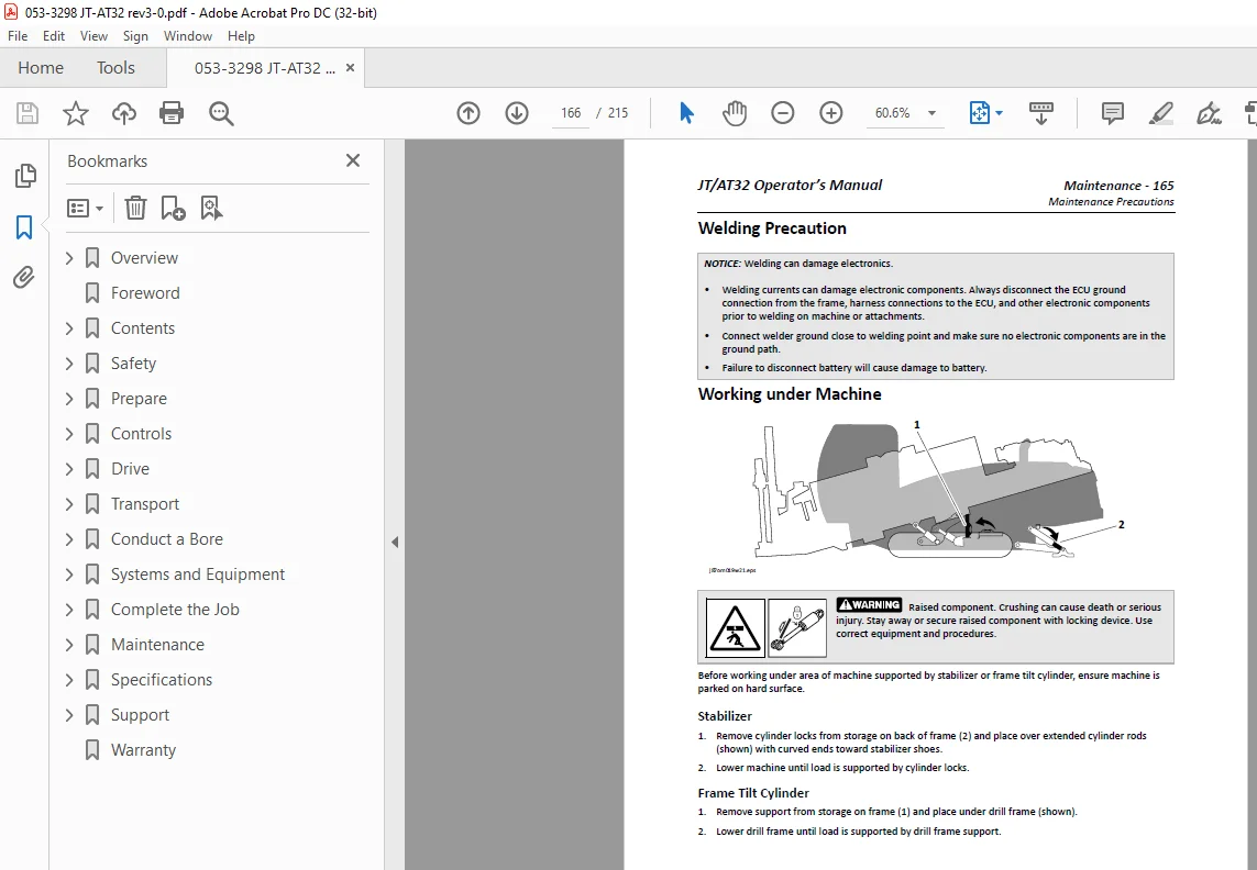
Welding Precaution 166
Working under Machine 166
Recommended Lubricants 167
Engine Oil Temperature Chart 168
Approved Coolant 168
Approved Fuel 169
Diesel Exhaust Fluid (DEF) 170
Exhaust Cleaning 171
Drill Maintenance Interval Chart 172
Drill Procedures 175
Hydraulic Accumulator 175
Air Intake System 175
Battery 176
Battery, Wireless Remote Control 179
Coolant 179
Crankcase Breather Tube 180
Drilling Fluid Y-Strainer 180
Dust Ejector Valve 180
Engine Compartment 181
Engine Drive Belt 181
Filter, Air 182
Filter, Crankcase Breather 182
Filter, DEF Pump 183
Filter, DEF Tank 183
Filter, Fuel 184
Filter, Hydraulic 184
Fluid Pump 184
Fluid, Hydraulic 185
Hydraulic Hoses 186
Hydraulic Tank 186
Inner Water Swivel 187
Oil, Anchor Gearbox 188
Oil, Engine 188
Oil, Fluid Pump 189
Oil, Ground Drive Gearbox 189
Oil, Rotation Gearbox 190
Pipe Auto-Lubricator 191
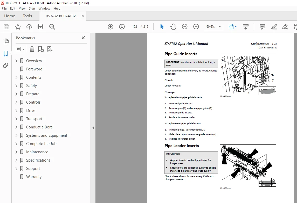
Pipe Guide Inserts 192
Pipe Loader Inserts 192
Radiator 193
Radiator Cap 193
SaverLok System 194
SaverLok Inner Drive Collar 196
Slide Cartridge Wear Pads 196
Thrust Rollers 197
Tool Joint Compound 198
Track Support Slide Pads 199
Track Tension 200
Water Separator 201
Wrench Jaw Inserts 201
Downhole Tool Maintenance Interval Chart 202
Downhole Tool Procedures 202
Lube Rockmaster Tool 202
Rebuild Rockmaster Tool 202
Specifications 204
JT/AT32 205
EU Declaration of Conformity 210
UK Declaration of Conformity 211
Support 214
Registration 214
Procedure 214
Resources 214
Publications 214
Ditch Witch Training 214
Warranty 215
Need help? Contact: [email protected]
S.V