Ditch Witch JT3510 Spare Parts Manual 053-446 PDF
$29.95
Ditch Witch JT3510 Parts Manual (053-446) is a comprehensive guide for precise identification and replacement of components, ensuring efficient maintenance for optimal performance of the specified equipment.
Description
Ditch Witch JT3510 Parts Manual 053-446 – PDF DOWNLOAD
FILE DETAILS:
Ditch Witch JT3510 Parts Manual 053-446 – PDF DOWNLOAD
Language : English
Pages : 434
Downloadable : Yes
File Type : PDF
IMAGES PREVIEW OF THE MANUAL:
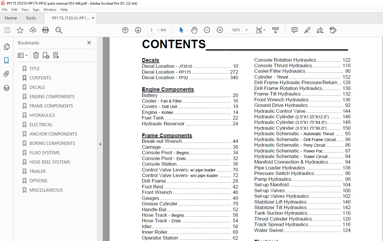
TABLE OF CONTENTS:
Ditch Witch JT3510 Parts Manual 053-446 – PDF DOWNLOAD
Decals
Decal Location – JT3510 10
Decal Location – PP175 272
Decal Location – TP32 340
Engine Components
Battery 20
Cooler – Fan & Filter 16
Covers – Drill Unit 18
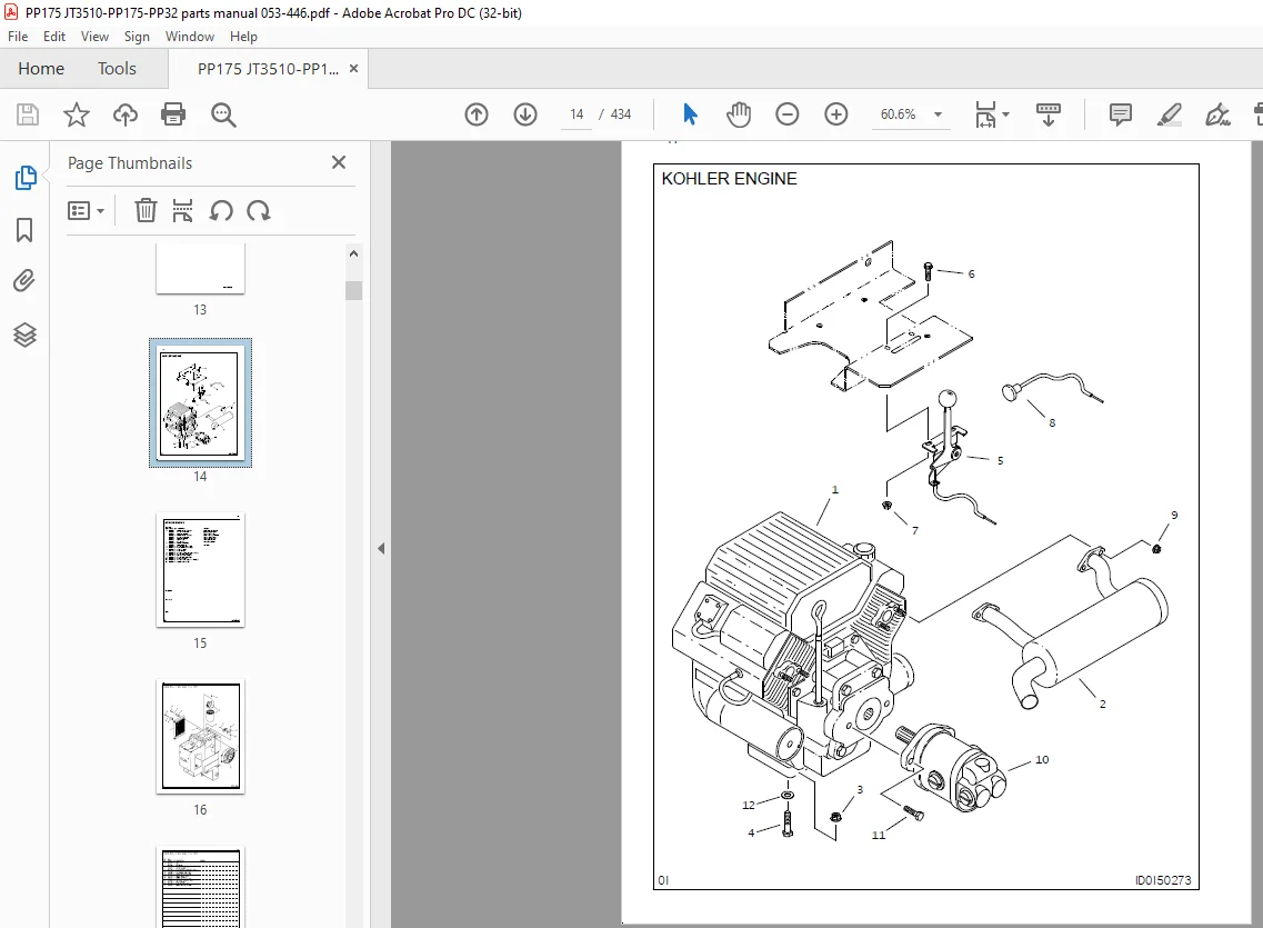
Engine – Kohler 14
Fuel Tank 22
Hydraulic Reservoir 24
Frame Components
Break-out Wrench 44
Carriage 30
Console Pivot – Begins 34
Console Pivot – Ends 32
Console Station 36
Control Valve Levers- w/ pipe loader 70
Control Valve Levers- w/o pipe loader 72
Drill Frame 28
Foot Rest 42
Front Wrench 46
Gauges 48
Grease Cylinder 78
Handle Bar 52
Hose Track – Begins 56
Hose Track – Ends 54
Idler 58
Inner Roller 60
Operator Station 62
Pipe Loader 64
Pipe Loader Gripper 66
Pipe Loader Mounts 68
Rotation Drive Gear Box 80
Stabilizer Arm 74
Stabilizer Pivot/Pad 76
Strobe Light Drill Frame 40
Tension Spring 50
Track Group 38
Hydraulics
2-Speed Shift Hydraulic 112
2-Speed Shift Hydraulic – Console 114
Auto Boring System Hydraulics 126
Breakout Wrench Hydraulics 134
Case Drain Hydraulics 108
Console Pressure/Return Hydraulic 106
Console Rotation Hydraulics 122
Console Thrust Hydraulics 118
Cooler/Filter Hydraulics 90
Cylinder – Thrust 152
Drill Frame Hydraulic Pressure/Return 128
Drill Frame Rotation Hydraulics 130
Frame Tilt Hydraulics 132
Front Wrench Hydraulics 136
Ground Drive Hydraulics 92
Hydraulic Control Valve 144
Hydraulic Cylinder (2 0”X1 25”X12 0”) 146
Hydraulic Cylinder (3 5”X1 75”X4 0”) 148
Hydraulic Cylinder (3 5”X1 75”X6 0”) 150
Hydraulic Schematic – Automatic Thrust 85
Hydraulic Schematic – Drill Frame Circuit 98
Hydraulic Schematic – Pony Circuit 86
Hydraulic Schematic – Power Pac 87
Hydraulic Schematic – Trailer Circuit 84
Manifold Connection & Hydraulics 94
Pipe Loader Hydraulics 138
Pressure Switch Hydraulics 96
Pump Hydraulics 98
Set-up Manifold 104
Set-up Valves 100
Set-up Valves Hydraulics 102
Stabilizer Lift Hydraulics 140
Stabilizer Tilt Hydraulics 142
Tank Suction Hydraulics 110
Thrust Cylinder Hydraulics 120
Track Spread Hydraulics 116
Water Swivel 124
Electrical
Electrical Diagram – Console – Begins 170
Electrical Diagram – Console – Ends 164
Electrical Diagram – Drill Frame – Begins 160
Electrical Diagram – Drill Frame – Ends 156
Electrical Diagram – Pony Engine 162
Electrical Diagram – Umbilical – Begins 182
Electrical Diagram – Umbilical – Ends 176
Electrical Schematic 188
Grounding Cables 194
Anchor Components
Anchor Drive Hydraulics 204
Auger Anchor Parts 198
Auger Driver 206
Auger Driver Hydraulics 208
Extended Anchor Parts 200
Hydraulic Stake Driver 212
Spring Loaded Pin 202
Stake Anchor Parts 210
Boring Components
Pipe Box – Begins 218
Pipe Box – Ends 216
Pipe Box Sling 220
Fluid System
Antifreeze Tank 224
Centrifugal Pump 262
Grounding Hardware 266
Large Centrifugal Hydraulics 254
Large Centrifugal Mounting 252
Large Centrifugal Plumbing – Begins 258
Large Centrifugal Plumbing – Ends 256
Mud Mixing 234
Mud Mixing Platform 230
Mud Mixing Platform 268
Mud Motor Hydraulics – High Pressure 238
Mud Motor Hydraulics – Low Pressure 236
Mud Pump 364
Mud Pump Plumbing 240
Mud Supply Line 242
Series/Parallel Valve 232
Small Centrifugal Hydraulics 246
Small Centrifugal Plumbing – Begins 250
Small Centrifugal Plumbing – Ends 248
Small Centrifugal Pump Mounting 244
Wash Wand 260
Water Tank 226
Water Tank System 228
Power Pack
Auxiliary Pump 304
Battery 282
Cold Start Kit 310
Dual Battery Options 308
Engine 274
Engine Mount 276
Exhaust Tube 278
Filter Cooler 296
Fuel Tank 298
Grill & Frame 288
Hydraulic Tank 300
Main Pump 302
Mud Pump 306
Panel Insulation 290
Rear Panels & Insulation 292
Relay Board 294
Throttle 284
Top Panel – Alarm & Strobe Light 280
Variable Throttle Installation 286
Hose Reel
Bottom Reel Motor Hydraulics 336
Control Panel 322
Electrical Umbilical Reel 316
Lower Hose Reel 332
Reel Drive Motor 334
Reel Housing 314
Reel Lock Pin 318
Reel Valve Hydraulics – Begins 326
Reel Valve Hydraulics – Ends 324
Swivel Guard 320
Top Reel Motor Hydraulics 330
Upper Hose Reel 328
Trailer
Air Brake 366
Air Brake Lines 368
Cover – Trailer 346
Drum & Hub 360
Electric Brake 362
Electrical Diagram – Brake 356
Electrical Diagram – Lights 354
Floor Boards 344
Frame – Trailer 342
Grid Assembly 374
Ramp Lock 352
Tag Light Mounting 348
Tire & Wheel 370
Tool Box 372
Trailer Axle Air 364
Trailer Axle Electric 358
Trailer Ramp 350
Options
Anti-Freeze Tank 378
Centrifugal Hydraulics 404
Electrical Umbilical Reel 418
Filter Cooler 402
Hose Reel Plumbing 396
Hose Reel Power 398
Large Centrifugal Mounting 412
Large Centrifugal Plumbing 414
Large Reel Motor Hydraulics 416
Mud Mixing 386
Questions? Email us: [email protected]
S.M