Parts Manual for Ditch Witch JT60 All Terrain Tier 3 & 4i 053-2629 PDF
$34.95
Description
Ditch Witch JT60 All Terrain Tier 3 & Tier 4i Parts Manual 053-2629 – PDF DOWNLOAD
FILE DETAILS:
Ditch Witch JT60 All Terrain Tier 3 & Tier 4i Parts Manual 053-2629 – PDF DOWNLOAD
Language : English
Pages : 951
Downloadable : Yes
File Type : PDF
IMAGES PREVIEW OF THE MANUAL:
TABLE OF CONTENTS:
Ditch Witch JT60 All Terrain Tier 3 & Tier 4i Parts Manual 053-2629 – PDF DOWNLOAD
Volume 1
Decals
Decal Location 10
Engine Components
Battery 36
Covers – Instrument Panel 34
Covers – Side Panels, Front 30
Covers – Side Panels, Rear 32
Covers – Top Panels, Front Hood 24
Covers – Top Panels, Mid Hood 26
Covers – Top Panels, Rear 28
Mounts 18
Oil Drain and Filter 22
Service Parts 16
Skid 20
Sound Insulation – Engine Covers 38
Sound Insulation – Engine Skid Assembly 40
Engine Tier 3
Cooling System – Deaeration 48
Cooling System – Fan 46
Cooling System – Plumbing 50
Exhaust System 52
Fuel System 54
Intake 44
Engine T4i
Cooling System – Deaeration 62
Cooling System – Fan 60
Cooling System – Plumbing 64
Exhaust System 66
Fuel System 68
Intake 58
Frame Components
2 Post ROPS 126
Carriage 82
Drill Frame Covers/Locks/Switches 128
Fuel Tank 124
Gearbox, Inner Drive 92
Gearbox, Rotation – AT 84
Gearbox, Rotation – JT 88
Grease Cylinder 120
Hose Track (Nested) – to Carriage 100
Hose Track (Nested) – to Drill Frame 102
Hydraulic Cylinder – 5 50” x 3 00” X 3 00” 112
Idler 116
Pivot 72
Rack Mounting 74
Roller 118
Spindle Drive – AT 94
Spindle Drive – JT 96
Stabilizer, Rear 122
Thrust Coupler and Shock 78
Thrust Drive Gearbox 80
Thrust Drive Rack 76
Track Group 114
Wire Line Kit 98
Wrench Assembly 104, 106, 108
Wrench Pipe Guide 110
Cab
A/C Plumbing 138
Console, Left 150
Console, Overhead 154
Console, Right 152
Controller 156, 158
Door 136
Dual Axis Joystick 160
Exterior 132
Frame 142
Heater Hose 140
Interior 134
Mount 144
Seat – Belt – Cover 146, 148
Volume 2
Hydraulics
Anchor Cylinder 250
Anchor Motor 248
Anchor Valve 246
Auxiliary Pump 184
Case Drain – AT 194
Case Drain – JT 192
Case Drain, Flushing 198
Case Drain, Thrust 196
Cylinder – 2 0” x 1 00” x 8 0” 280
Cylinder – 2 0” x 1 25” x 24 0” 282
Cylinder – 3” x 1 75” x 8” 284
Cylinder – 4 0” x 2 00” x 10 0” 288
Cylinders – 4 0” x 2 0” 286
Fluid Pump Plumbing – Air Hammer 236
Fluid Pump 234
Frame Tilt 264
Gripper, Front 272
Gripper, Rear 274
Ground Drive Load Sense 222
Ground Drive 238
Hose Track Mount 200
Hose Track 202
Inner Rotation 224
Load Sense Pressure Hydraulics 190
Load Sense Suction/Signal 188
Lubricator Hydraulics 276
Main Frame Bulkhead 178
Oil Filter 172
Oil Return 170
Pipe Lifter 270
Pipe Loader/Wrench Supply & Return 266
Pipe Shuttle 268
Pump Mount 168
Remote Filter 212
Reservoir 174
Rotation Gauge Valve 182
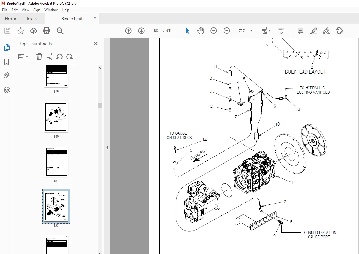
Rotation Hydraulics 180
Rotation Motor Hyd – AT 206, 208, 210
Rotation Motor Hyd – JT 204
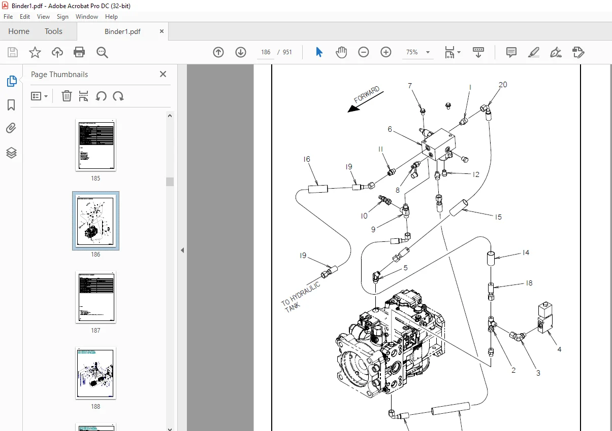
Rotation POR & Flushing 186
Rotation, Thrust and Fluid Gauges 176
Schematic 164
Seat Rotation 278
Setup Valve Supply & Return 258
Shuttle Stop 262
Spindle Brake/Thrust Brake/2-Speed 216
Stabilizer Hydraulics 260
Thrust Drive 232
Thrust Hydraulics 230
Thrust Valve – AT 226
Thrust Valve – JT 228
Track 2 Speed 214
Track Brake 220
Track Case Drain 240
Track Shift 218
Wrench & Anchor Valve 242
Wrench Rotate Hydraulics 256
Wrench, Front 252
Wrench, Rear 254
Wrench Valve 244
Volume 3
Electrical
Battery Cables 306
Diagram – Carriage Harness 352
Diagram – Drill Frame Harness 342, 348
Diagram – E S I D Switch Harness 378
Diagram – Engine/Frame Harness 312
Diagram – Engine Harness T3 316
Diagram – Engine Harness T4i 318
Diagram – Hose Track Harness 356
Diagram – Main Frame Harness 324
Diagram – Operator Station 358, 368
Diagram – Overhead Switch Panel 374
Diagram – Relay Panel Harness 328, 334
Diagram – Setup Valve Harness 320
Diagram – Worklight Harness 340
Electrical Schematic 292
Engine Electric Cables 308
Relay Panel 310
Anchor Systems
Anchor Pipe Guide 382
Anchor System 384
Anchors 386
Auto-Luber Assembly 388
Grease Pump 390
Lubricator Mount 392
Fluid System
Fluid Pump 408, 410
Fluid Pump Assembly 396
Fluid Pump Drain 402
Fluid System – Carriage 404
Fluid System – Hardline 406
Liner Wash Tank 400
Wash Wand 412
Pipe Loader Systems
Gripper Cylinder 426
Guard Lock Pin 436
Guard, Rear 432, 434
Pipe Loader Lifters 420
Pipe Shuttle, Front 422
Pipe Shuttle, Rear 424
Shuttle Guard 430
Shuttle Mount, Front 416
Shuttle Mount, Rear 418
Shuttle Stop 428
Accessories
Air Hammer 462
Drilling Fluid Transfer 442
Fluid Mixing Accessories 444
Grounding Hardware 448
Mirrors 440
Pipe Box, AT (Short) 456
Pipe Box, AT (Tall) 450
Pipe Box, JT (Short) 458
Pipe Box, JT (Tall) 452
Pipe Box, PPF #800 (Short) 460
Pipe Box, PPF #800 (Tall) 454
Working Light 446
Miscellaneous
Bolt/Nut Torque Chart 466
Filters 472
Optional Kits 472
Related Publications 472
Replacement O-Ring Chart 471
Warranty Registration 474
Customer Support: [email protected]
https://vimeo.com/902204435?share=copy
S.V