Ditch Witch JT60 / JT60 All Terrain Tier 4 Operator’s Manual PDF
$28.95
Description
Ditch Witch JT60 / JT60 All Terrain Tier 4 Operator’s Manual 053-2955 – PDF DOWNLOAD
FILE DETAILS:
Ditch Witch JT60 / JT60 All Terrain Tier 4 Operator’s Manual 053-2955 – PDF DOWNLOAD
Language : English
Pages : 256
Downloadable : Yes
File Type : PDF
IMAGES PREVIEW OF THE MANUAL:
TABLE OF CONTENTS:
Ditch Witch JT60 / JT60 All Terrain Tier 4 Operator’s Manual 053-2955 – PDF DOWNLOAD
Overview 2
Serial Number Location 3
Intended Use 4
Equipment Modification 4
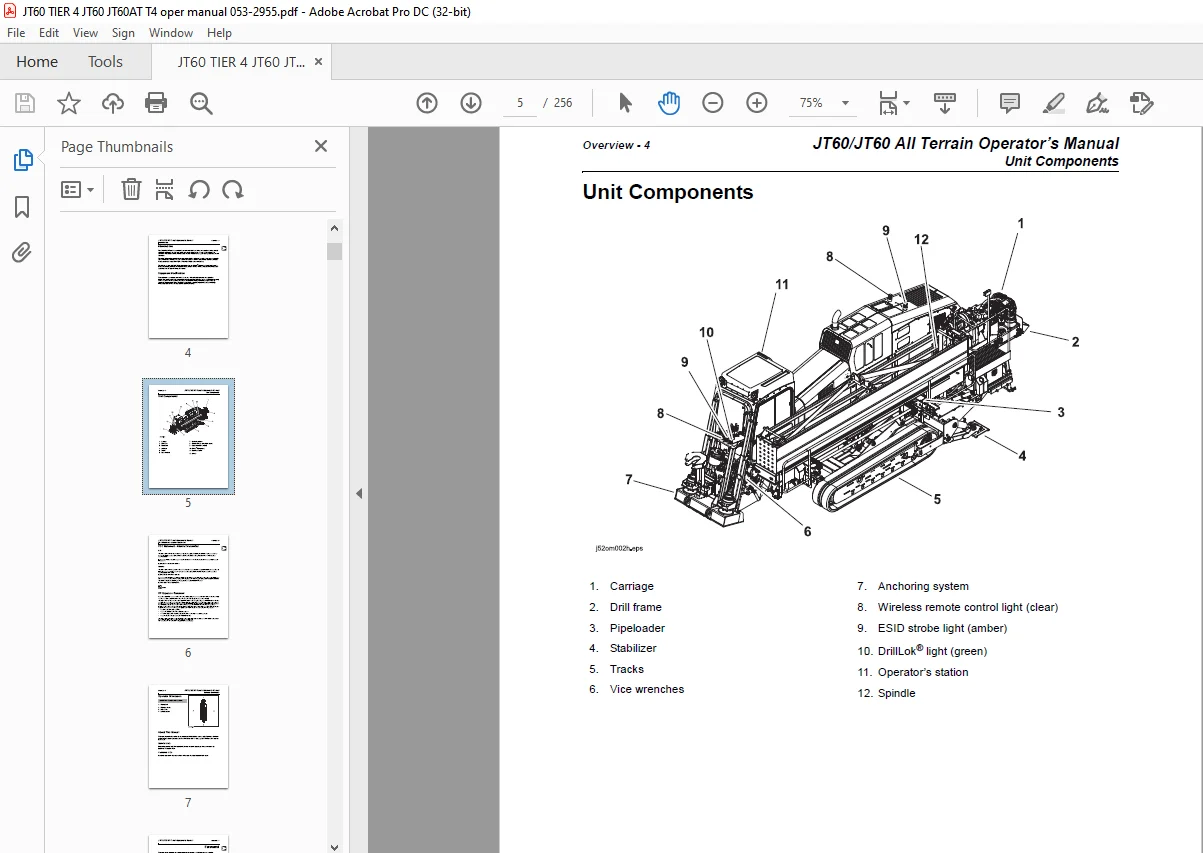
Unit Components 5
FCC Statement – Internal Transmitter 6
RF Exposure Statement 6
Operator Orientation 7
About This Manual 7
Bulleted Lists 7
Numbered Lists 7
Foreword 8
Contents 10
Overview 10
1 10
Foreword 10
7 10
Safety 10
11 10
Controls 10
21 10
Operation Overview 10
65 10
Prepare 10
69 10
Drive 10
93 10
Transport 10
99 10
Conduct a Bore 10
105 10
Systems and Equipment 10
129 10
Complete the Job 10
183 10
Service 10
189 10
Specifications 11
235 11
Support 11
241 11
Service Record 11
245 11
Appendix 11
247 11
Safety 12
Guidelines 13
California Proposition 65 Warning 13
Emergency Procedures 14
Electric Strike Description 14
If an Electric Line is Damaged 15
If a Gas Line is Damaged 16
If a Fiber Optic Cable is Damaged 17
If Machine Catches on Fire 17
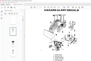
Safety Alert Classifications 18
Machine Safety Alerts 19
Controls 22
Setup Console 23
Anchoring System Console 26
Left Control Console 28
Engine Display 28
Main Menu 30
Status Indicators 31
ESID Strike Display 32
ESID Application Display 33
Drilling Controls 34
Wrench Control 38
Right Control Console 41
Operation Controls 41
Gauges and Indicators 43
Drill/Drive Control 46
Seat 48
Cab Controls 49
Top/Rear 49
Wireless Ground Drive Controller 51
Override Box 56
Battery Disconnect 59
Engine Compartment 60
Rear Console 62
Wireline Controls 64
Miscellaneous Controls 65
Operation Overview 66
Planning 67
Setting Up at Jobsite 67
Drilling 68
Backreaming 69
Backreaming Tips 69
Leaving Jobsite 69
Storing Equipment 69
Prepare 70
Gather Information 72
Review Job Plan 72
Notify One-Call Services 72
Examine Pullback Material 72
Arrange for Traffic Control 72
Plan for Emergency Services 72
Inspect Site 73
Identify Hazards 73
Select Start and End Points 74
Classify Jobsite 75
Select a Classification 75
Apply Precautions 76
Plan Bore Path 78
Recommended Bend Limits 79
Entry Pitch 83
Minimum Setback 83
Minimum Depth 84
Bore Path Calculator 84
Prepare Jobsite 87
Mark Bore Path 87
Prepare Entry Point 87
Check Supplies and Prepare Equipment 88
Check Supplies 88
Prepare Equipment 89
Select Drilling Mode 90
Prepare Drilling Unit 91
Assemble Accessories 93
Drive 94
Start Unit 95
Steer Unit 95
Single Joystick Ground Drive 95
Dual Joystick Ground Drive 95
Tips to Reduce Track Wear 96
Safe Slope Operation 97
Shut Down Unit 98
Transport 100
Lift 101
Pipe Box Lifting Procedure 101
Haul 102
Load 102
Tie Down 103
Unload 104
Retrieve 104
Conduct a Bore 106
Position Equipment 108
Connect Fluid System 108
Start System 109
Prime Drilling Fluid Pump 109
Operate Carriage Control 110
Clamp Pipe 111
Assemble Drill String 112
Prepare Beacon Housing 112
Attach Transition Sub 113
Attach Beacon Housing 113
Connect Drill Pipe 114
Drill First Pipe 115
JT Mode/AT Dirt Mode 115
AT Rock Mode 115
Swab the Hole 116
Enable Automated Pipeloader System 116
Add Pipe 117
Correct Direction 119
Basic Rules 119
Procedure 120
Drill Head Position 120
Use AutoCarve 121
Operation 122
Record Bore Path 123
Surface Drill Head 124
Backream 125
Remove Pipe 127
Remove Pullback Device 129
Systems and Equipment 130
Anchor System 132
Anchors 133
Alternate Anchoring 135
Electric Strike System 136
FCC Statement 136
Assemble Voltage Detector 137
Test Strike System 137
Troubleshoot Strike System 138
Use Electric Strike Simulator 140
Drilling Fluid 142
Guidelines 142
Polymer 142
Bentonite 143
Mixtures 143
Drilling Fluid Requirements 145
Funnel Viscosity 146
DrillLok® System 147
Overview 147
Downhole Tools 148
Nozzles 148
Bits 148
Beacon Housings 149
Backreamers 150
Backream Fluid Requirements 151
Hydratong Wrenches 153
Scribe Line Method 155
Drill Pipe 156
Perform Regular Drill Pipe Care 156
Use Drill Pipe Correctly 158
Pipe Boxes 160
Remove/Install Pipe Box 160
Add/Remove Single Pipe 162
Wireless Ground Drive Controller 167
Before each use 167
Operation 167
Troubleshooting 168
Cruise Control 170
Engage 170
Adjust Settings 170
Override 171
Disengage 171
Resume 171
Wireline Tracking 172
Operation 172
Diagnostic Codes 174
Electronic Controlled Engine Overview 174
Reading Engine Diagnostic Codes 174
Engine Diagnostic Codes 174
Reading Machine Diagnostic Codes 175
Machine Diagnostic Codes 176
Complete the Job 184
Antifreeze Drilling Unit 185
Add Antifreeze 185
Reclaim Antifreeze 186
Rinse Equipment 187
Using Washwand 187
Disconnect 188
Stow Tools 188
Service 190
Service Precautions 191
Welding Precaution 191
Washing Precaution 191
Working Under Drilling Unit 192
Recommended Lubricants/Service Key 193
Approved Coolant 194
Approved Fuel 194
Diesel Exhaust Fluid (DEF) 195
Each Use 197
Downhole Tools 197
Startup/10 Hour 199
Drilling Unit 199
50 Hour 206
Drilling Unit 206
Downhole Tools 211
200 Hour 211
250 Hour 212
500 Hour 213
Drilling Unit 213
1000 Hour 215
Drilling Unit 215
Change Diesel Exhaust Fluid (DEF) Tank Filter 219
2000 Hour 221
Drilling Unit 221
4500 Hour 225
As Needed 226
Drilling Unit 227
Specifications 236
Declaration of Conformity Information 241
Support 242
Procedure 242
Resources 242
Publications 242
Ditch Witch® Training 242
Warranty 243
Service Record 246
Appendix 248
Contact us: [email protected]
S.V