Trusted Business
Verified & Licensed
Virus Free Files
100% Safe Downloads
Secure Payment
SSL Protected
Instant Delivery
Available Immediately
Ditch Witch MT122 Attachment Operator’s Manual ID0677108 PDF
$14.95
Instant PDF Download
Available immediately
Save to Your Device
Download & keep forever
Antivirus Scanned
100% virus-free
Trusted Worldwide
175,000+ customers
Description
Ditch Witch MT122 Attachment Operator’s Manual ID0677108 – PDF DOWNLOAD
FILE DETAILS:
Ditch Witch MT122 Attachment Operator’s Manual ID0677108 – PDF DOWNLOAD
Language : English
Pages : 18
Downloadable : Yes
File Type : PDF
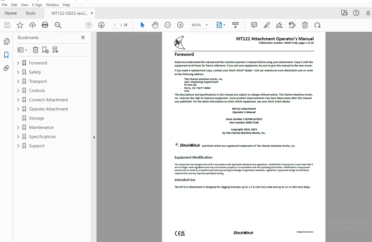
IMAGES PREVIEW OF THE MANUAL:
TABLE OF CONTENTS:
Ditch Witch MT122 Attachment Operator’s Manual ID0677108 – PDF DOWNLOAD
Foreword................................................................................................................................................................ 1
	MT122 Attachment Operator’s Manual.................................................................................................................................. 1
	Issue number 2.0/OM-6/2023 Part number ID0677108.................................................................................................................... 1
	Copyright 2020, 2023 by The Charles Machine Works, Inc.............................................................................................................. 1
		Equipment Modification.......................................................................................................................................... 1
		Intended Use.................................................................................................................................................... 1
Safety.................................................................................................................................................................. 2
	Safety Alert Classifications........................................................................................................................................ 2
	Safety Alerts....................................................................................................................................................... 3
Transport............................................................................................................................................................... 4
	Lift................................................................................................................................................................ 4
Controls................................................................................................................................................................ 4
	Microtrencher....................................................................................................................................................... 4
	Machine............................................................................................................................................................. 5
Connect Attachment...................................................................................................................................................... 6
	Set Up Microtrencher................................................................................................................................................ 6
		1. Position attachment frame on correct side of microtrencher for desired pull/push mode of operation and in desired offset position............................ 6
		2. Loosen latch bolt (1) on saw and lower bottom latch jaw (2).Lift frame up and into latching position with frame engaged in top (3) and bottom latch jaws..... 6
		3. Raise lower latch jaw up to attach frame to microtrencher.................................................................................................... 6
		4. Tighten latch bolt........................................................................................................................................... 6
	Attachment.......................................................................................................................................................... 7
		1. Position attachment on level surface with enough space behind it to accommodate machine...................................................................... 7
		2. Start engine................................................................................................................................................. 7
		3. Ensure attachment pins are disengaged........................................................................................................................ 7
		4. Tilt attachment plate (2) forward............................................................................................................................ 7
		5. Position attachment plate in the upper lip of receiver plate (1) on attachment............................................................................... 7
		6. Raise lift arms while tilting back attachment plate and engage pins.......................................................................................... 7
		7. Pins will automatically engage............................................................................................................................... 7
		8. Ensure lock pins are engaged by rotating attachment down. Verify that bottoms of lock pins are visible under attachment plate (shown)........................ 7
	Hydraulic Hoses..................................................................................................................................................... 8
		1. Remove dirt and debris from hydraulic couplers............................................................................................................... 8
		2. Connect male couplers on attachment to female couplers (3) on machine........................................................................................ 8
		3. Connect female couplers on attachment to male couplers (1) on machine........................................................................................ 8
		4. Ensure that connections are secure by pulling on hoses....................................................................................................... 8
	Electrical.......................................................................................................................................................... 8
Operate Attachment...................................................................................................................................................... 9
	Prepare Spoils Removal.............................................................................................................................................. 9
		1. Turn off vacuum excavator and ensure microtrencher blade is not turning...................................................................................... 9
		2. Connect vacuum hose on excavator to vacuum hose port on microtrencher........................................................................................ 9
		3. Operate vacuum excavator at full speed for best results...................................................................................................... 9
		1. Cap vacuum hose on microtrencher............................................................................................................................. 9
		2. Remove chute plate (1)....................................................................................................................................... 9
		3. Install spoils chute (2)..................................................................................................................................... 9
	Operate Microtrencher...............................................................................................................................................10
		1. Start SK machine.............................................................................................................................................10
		2. Engage attachment drive (auxiliary) in forward. BLADE WILL TURN..............................................................................................10
		3. Increase engine speed to full throttle.......................................................................................................................10
		4. Lower microtrencher as blade enters ground. Use tilt and curl controls to position attachment base flush against ground......................................10
		5. Slowly lower blade to digging depth..........................................................................................................................10
		6. Move track drive controls to begin microtrenching. MACHINE WILL MOVE.........................................................................................10
		7. Steer machine as needed......................................................................................................................................10
		8. When trench is complete, move track drive controls to neutral................................................................................................10
		9. Move throttle to half open...................................................................................................................................10
		10. Raise blade completely......................................................................................................................................10
		11. Stop blade rotation.........................................................................................................................................10
		12. Raise microtrencher.........................................................................................................................................10
		13. Drive machine away from trench..............................................................................................................................10
		14. Stop engine.................................................................................................................................................10
Storage.................................................................................................................................................................11
Maintenance.............................................................................................................................................................11
	100 ft (30.5 m).....................................................................................................................................................11
		1. Check bit condition using gauge (shown, 301-1507)............................................................................................................11
		2. As needed, drive out roll pin (2)............................................................................................................................11
		3. Remove bit (1)...............................................................................................................................................11
		4. Install new bit into holder..................................................................................................................................11
		5. Drive in new roll pin........................................................................................................................................11
	10-Hour.............................................................................................................................................................12
	As Needed...........................................................................................................................................................13
		1. Start SK machine and position microtrencher slightly above ground............................................................................................13
		2. Shut down SK machine.........................................................................................................................................13
		3. Remove 6 wingnuts (1) and cover (2)..........................................................................................................................13
		4. Remove 6 lug nuts (3)........................................................................................................................................13
		5. Remove blade (4).............................................................................................................................................13
		6. Clean threads (5)............................................................................................................................................13
		7. Install new blade (note direction of rotation)...............................................................................................................13
		8. Apply Loctite 242 or equivalent to 6 lug nuts and install with flat side toward blade........................................................................13
		9. Tighten to 300ft-lb (407N•m).................................................................................................................................13
		10. Install cover and secure with wingnuts......................................................................................................................13
Specifications..........................................................................................................................................................14
	EU Declaration of Conformity........................................................................................................................................15
	UK Declaration of Conformity........................................................................................................................................16
Support.................................................................................................................................................................17
	Procedure...........................................................................................................................................................17
	Resources...........................................................................................................................................................17
	Warranty............................................................................................................................................................18
S.S 02/24