Dongfeng DFA1101GZ5AD6J-907 Light Commercial Truck Operation Manual – PDF DOWNLOAD
$29.95
Dongfeng DFA1101GZ5AD6J-907 Light Commercial Truck Operation Manual – PDF DOWNLOAD
Description
Dongfeng DFA1101GZ5AD6J-907 Light Commercial Truck Operation Manual – PDF DOWNLOAD
FILE DETAILS:
Dongfeng DFA1101GZ5AD6J-907 Light Commercial Truck Operation Manual – PDF DOWNLOAD
Language :English
Pages :92
Downloadable : Yes
File Type : PDF
IMAGES PREVIEW OF THE MANUAL:
DESCRIPTION:
Dongfeng DFA1101GZ5AD6J-907 Light Commercial Truck Operation Manual – PDF DOWNLOAD
Foreword
This manual contains necessary procedures and instructions for the operation, inspection and maintenance for your DFA1101GZ5AD6J-907 truck.
This vehicle is equipped with the EQB140-20 DONGFENG Cum- mins diesel engine which could reach the European II displacement standard.
To obtain the optimum performance from your new vehicle is the common goal for all of us, and it depends largely on your care and familiarity of the operation and maintenance of the vehicles. We sincerely hope that you read this manual thoroughly, and make sure that you are familiar with the operation and maintenance before you using the new truck.
The manual is a part of your vehicle. Please keep it with your truck. The information and figures in this manual are correct when publishing. Due to continuous improvement on our vehicles, maybe there are some instructions in the manual that does not accord with the actual vehicles. Please inquire when you get some problem.
The Application Section of Testing Department, Commercial product R&D Institute of DONGFENG AUTOMOBILE CO., LTD. is in charge of compiling this manual. DFAC reserve the right to make changes at any time without notice.
As for vehicle saling, maintaining or spare parts purchasing, please consult with the local agency.
The manual uses the legal unit.
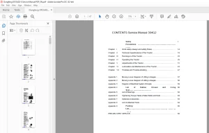
TABLE OF CONTENTS:
Dongfeng DFA1101GZ5AD6J-907 Light Commercial Truck Operation Manual – PDF DOWNLOAD
DFA1101GZ5AD6J-907 Operation Manual 1
Foreword 2
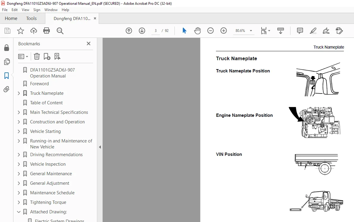
Truck Nameplate 3
Truck Nameplate Position 3
Engine Nameplate Position 3
Table of Content 4
Main Technical Specifications 8
Main Technical Specifications and Structure Features 8
Operational Data 9
Engine Parameter 9
Chassis Type and Structure Parameter10
1 Clutch10
2 Transmission10
3 Propeller shaft10
4 Front axle10
5 Drive axle10
6 Suspension system10
7 Wheel10
8 Steering system11
9 Brake system11
10 Frame11
11 Electric equipment and instruments11
12 Cab12
13 Tools equipment12
Construction and Operation13
Arrangement of the Cab13
1 Hazard waring lamp switch13
2 In strument panel13
3 Front fog lamp switch13
4 Wind channel13
5 Radio cassette13
6 Heater and air-conditioner switch13
7 Glove box13
8 Windshield washer fluid reservoir13
9 Fuse box13
10 Cigarette lighter13
11 Ashtray13
12 Windshield wiper and washer controlling rod13
13 Ignition lock13
14 Combined light switch13
15 Combination switch13
Doors14
Seats15
Instruments16
1 Fuel Gauge16
2 Water Temperature Gauge17
3 Tachometer17
4 Speedometer17
5 Air-pressure Gauge18
Indicators18
1 Taillamp Warning Indicator18
2 Exhaust Brake Indicator19
3 High Beam Indicator19
4 Charge Warning Indicator19
5 Fuel-water Separator Indicator19
6 Parking Brake Warning Indicator19
7 Safety Belt Indicator19
8 Fuel Warning Indicator20
9 Rear Fog Indicator20
10 Water Temperature Warning Indicator20
11 Oil Pressure Warning Indicator20
12 Brake-down Warning Indicator20
13 Air Filter Block Warning Indicator21
14 Turning Signal Indicator21
Keys21
Key Switch21
Light Combination Switch22
1 Light switch22
2 Turn signal light switch23
3 Dimmer switch23
4 Passing light switch23
5 Windshield Wiper and Washer Switch23
6 Hazard Warning Indicator Switch24
7 Front Fog Lamp Switch24
8 Rear Fog Lamp Switch25
Power Switch25
Exhaust Brake Switch25
Air Horn and Electric Horn Shift Switch26
Air Drier Switch26
Dome Lamp and Glove Box26
Cab Skylight27
Air Conditioning System27
1 Ventilator27
2 Air-conditioner27
Levers, Steering Wheel and Accessories28
1 Transmission gear shift lever28
2 Parking brake knob29
3 Steering wheel adjustment29
4 Rearview mirror and bottom view mirror adjustment30
5 Cigarette lighter30
6 Ash tray30
7 Radio cassette31
1 Tuning switch31
2 Balance switch31
3 Volume control switch31
4 Outlet switch31
5 Tape outlet31
6 Fast backward switch31
7 Fastforward switch31
8 Tape/radio shift switch31
9 Power switch31
10 Indicator31
11 Button to adjust the hour31
12 Button to adjust the minute31
13 Time set button31
14 Display31
15 Mode condition choose switch31
16 Spare tyre32
17 Expansion tank32
18 Glass regulator33
19 Quarter window33
Tilting Cab33
1 Precautions before Tilting Cab33
2 Tilt Operating33
3 Lock Operating34
Vehicle Starting35
Engine Starting35
1 Check the oil and coolant level35
2 Check the fuel level35
3 Without the air-filter, the engine is forbidden to operate35
4 First using of a new vehicle and stopping for a long time, it has to use the hand priming lever of the fuel pump to pump fuel to bleed the air in the fuel system35
5 Make sure that the transmission gear shift lever is on the neutral position35
6 Turn the key switch to “ON” position, and check every warning indicator lamp to see whether is on or not35
7 Depress the accelerator to middle speed position and clutch pedal fully, and turn the key switch to the “START” position to start the engine35
8 After the engine has been started, release the key, and gradually release the accelerator pedal till idle running Be sure to inspect the oil pressure within 15 seconds35
Engine Starting (when the cab is tilted)36
Running-in and Maintenance of New Vehicle37
Before Running-in37
Running-in Period38
After Running-in38
Driving Recommendations39
1 When the engine is cool, do not start to run hurrily Do the cold start, first allow it to be a permissible speed, and the exhaust smoke is bluish-white, so the oil pressure engine combusion will be stable along with the heating of the engine39
2 Never run-up the engine speed unnecessarily If the temperature of the cooling water is low, it will cause the engine damag39
3 The engine speed can’t exceed 2,500r/min before the driving mileage is at 4,000km39
4 Avoid full-throttle starts fully and brake suddenly, the first case will cause the clutch damage or the tyre wear while the second case will accelerate wear on both the tyre and brake linings39
5 Don’t overload driving It will shorten the service life of the vehicle40
Driving on a slope40
Clutch Operation40
Double-foot-clutch Method for Shifting41
The Use of Warning Triangle41
Parking42
Vehicle Inspection43
Driver’s Daily Inspection43
1 The vehicle should be parked on the flat ground43
2 The switch key must be set on the OFF position43
3 The parking brake is applied properly43
4 The transmission gear shift lever should be in neutral43
1 Check the driver’s seat43
2 Check mirrors43
3 Check lock condition of the door44
4 Check the fluid level of the windshield washer44
5 Check the cooling water level44
1) Before adding cooling water, check the engine and radiator for any sight of leakage, please repair it first if there is Fi44
6 Check the seal and function of the pressure cover of the filling hole44
Vehicle External Inspection44
1 Check the engine oil level44
2 Check the remaining fuel45
3 Check the brake pipes to see whether it is leaky45
4 Check the bolts and nuts of steering system45
5 Check the front and the rear leaf spring and their bolts and nuts45
6 Check the tyre pressure45
7 Check the electrolyte height of battery45
8 Check the harness(whether is worn by other parts) and earthing45
9 Check each gauge45
10 Check the horn46
11 Check the windshield wiper and washer46
12 Check the front and the rear lamps47
1 Headlamp47
2 Front fog lamp47
3 Front lamp47
4 Turning signal lamp47
5 Rear clearance lamp47
6 Front clearance lamp47
7 Side clearance marker47
8 Tail combined lamps (rear turning signal lamp, tail lamp, brake lamp, rear fog lamp, reversing lamp)47
9 Licence lamp47
13 Check the engine, steering system, transmission and rear axle to see whether there is any leakage47
14 Check the steering wheel for free turning and axial play47
15 The exhaust gas inspection48
16 Check the brake48
17 Check the steering system48
10 Checking after test running48
18 Other49
General Maintenance50
Air Filter50
1 Take out the filter cartridge and put it on a plain plate and pat it Put a light into the filter to check for wear or hole, as well as to check the washer, replace it if there is something abnormal50
2 Using the dry compressed air of 05MPa to blow off the accumulated dust from the inside toward the circumference of the circle Replace the cartridge immediately if any of the following situations appeared:50
a) The outer cartridge has damaged or been cleaned more than 5 hours50
b) After 48000km50
Diesel Oil Prefilter51
Fuel Filter and Fuel-water Separator51
Oil Filter51
Fuel Tank Draining52
Fuel Pump52
Exhaust GasTurbo Supercharger53
1 The users can not loosen or tighten the adjusting nut of the connecting rod to adjust the opening pressure of the ehaust valve Otherwise, it is harmful to the engine53
2 Do not load or trample the connecting rod in any case53
3 If you find the inlet pipe is leaky or the supercharger is abnormal during driving, stop the vehicle and check them But do r53
1 Get rid of the dust and oily dirt of the surface of the supercharger54
2 Remove the supercharger from the engine but do not carry it by the connecting rod54
3 Remove the inlet pipe first then the exhaust valve adjustment54
4 Remove the compressor casing, turbing casing and inlet and return oil flange54
5 Clean the compressor casing, turbing casing and the surface of the two impeller54
6 Fill some clean washer liquid from the inlet and rotate the impeller by hand until the impeller works well54
7 Assemble and install to the engine54
Air Drier55
Check the Oil Level, and Refill the Clutch Oil Reservior55
The Transmission Lubricating Oil55
The Rear Axle Main Reductor Lubricating Oil56
1 Inspection screw56
2 Oil drain screw56
Power Steering Lubricating Oil57
1 Oil filler cap with oil level stick57
2 Hydraulic oil cartridge57
3 Oil reservior57
1 Block the rear wheel with triangle bolster, set the transmission to neutral and rise the front axle with the jack to make the wheel away from the ground57
2 Screw down the inlet and outlet oil tube joint to exhaust the steering system oil, and start the engine at the same time, turn the steering wheel57
3 After make sure the oil has been drained off, open the cap of the oil reservior to replace the hydraulic oil cartridge57
4 After replace the cartridge, first refill the oil reservior and then start the engine to idle for a short time, then cut off 58
Battery Checking and Maintenance58
1 Electrolyte58
2 Plate58
1 Float59
2 Reading59
3 Level of electrolyte59
Fuse59
Suspension59
Tire Rotation60
1 The differential of outer diameter of two rear axle tirs is no more than 12mm Mount the smaller one to the inside wheel60
2 Mount the same type, less wear and blanced tires on the front wheel60
3 After rotation, the turning direction of tires should be opposite from its former mounting direction60
4 New tires must be used in pair60
5 Be sure to mount the tires of the same size in the same shaft, otherwise it will cause braking deviation, cab swing and lost controlled steering60
6 Check whether there is any scars on the wheel hub bolts and wheel nuts For the sake of the safty, whenever there is screw damage in bolt or nut, it must be replaced in pairs as the other part may also be damaged60
7 Check the connecting (ball) surface of the tire rim and the installing hole to see whether there is any deformation or damage If there is, replace it And if there is any damage on the ball surface of tire nut, replace it, too60
8 Check the rim of the tires, if there is any cracks, replace it60
9 When mount tires in pair, the air intake-outer and the air intake-inner must be separated in order to breathe air in61
Clean and Replace the Wiper Blades61
1 Pull out hte wiper arm62
2 Untighten the lock pin, and push to remove the blade62
3 Install a new blade into the wiper arm, if a sound “clicks” can be heard, it shows that the lade is well fixed62
General Adjustment63
Using Engine in a Environmental Protection Standard63
1 As for those who dismantle the leaden seal of engine without permission, the DongFeng Automobile Co, Ltd would consider they have given up the right of obtaining service63
2 The engine has been reached the requirements of national environment law before leaving the factory, so the users can not cha63
3 During the maintenance you should follow the principles below:63
a) Do the maintenance or change the three filters at a certain interval and you have to quiken your changing step if the outsi63
b) Use the specific or recommended oil and change them at certain intervals63
c) Use different type of diesel oil of high quality according to the local temperature63
d) Please do not allow the shortage of engine liquid or lubricating oil63
e) Check the supercharger, intercooler, and the seal condition of the in and out pipe, avoid the leakage64
f) The start and stop of the engine64
7 Use the recommended oil filter and diesel oil filter catridge64
8 Check the clearance of the inlet and outlet valve following the guidance of the instructions64
9 The idling revolution has its own normal standard, so the users can not adjust, because the low idling revolution will cause the accelerated smoke acceed quota64
Drain Water Out from the Cooling System64
Check the Opening Temperature of the Thermostat65
Adjustment of Fan Belt65
Pump Fuel Manually and Bleed Air Out of Fuel Supply System66
1 Bleed screw66
2 Handle screw cap66
3 Drain plug66
Water-leak Hole of the Water Pump66
Air Valve Clearance Adjustment66
1 Camshaft gear66
2 Timing of pin66
3 Gear case cover66
1 Remove the air valve cover67
2 Press the timing pin of the engine(on the timing gear chamber close to fuel injecting pump), and use a wrench to turn the eng67
3 During this time, you must adjust the following air valve clearance(counted from the front to the end): valve 1(inlet), 2 (exhaust), 3 (inlet), 6 (exhaust)67
4 After the adjustment, make marks on the pulley and the timing gear chamber, then turn the engine to align the marks67
5 Then adjust the following air valve clearance: 4 (exhaust), 5 (inlet), 7 (inlet), 8 (exhaust)67
Adjustement of Clutch67
1 Adjust the clearance between the push rod and the piston of master cylinder to 02~07mm When made the adjustment, loosen th67
2 Adjust the free travel of slave cylinder push rod to 3~5mm and tighten the lock nut68
3 After the above adjustments has finished, the travel of master cylinder push rod and slave cylinder push rod should be 20~24mm, and 17~20mm, the free travel of clutch pedal should be 30~40mm68
Air Release of Clutch68
1 Fill up the clutch oil reservoir with composite brake liquid, and make the air pressure of the air tank reached to 650kPa68
2 First remove the dust cap of clutch slave cylinder, and loosen its bleeding bolt, then engage a matchable hose to bleeding bo68
3 Screw on the bleeding bolt, trample down the clutch pedal, then screw off the bleeding bolt to exhaust the air in the oil, then screw on again and release the clutch pedal69
4 Do the 3rd step repeatedly until there is no bubbles come out and you can feel the clutch can be disengaged totally69
Adjustment of Brake Clearance69
Brake system71
1 Bracket-hose71
2 Front-brake chamber71
3 Elbow joint71
4 Alarmer71
5 Parking air tank71
6 Wet air tank71
7 Drain valve71
8 Four-circuit protection valve71
9 Unloader valve71
10 Air drier71
11 Two-way valve71
12 Quick-release valve71
13 Rear-brake chamber71
14 Loading sensing valve71
15 Rear air tank71
16 Front air tank71
17 Electromagnetic valve71
18 Exhaust brake valve71
19 Quick-release valve71
Adjustment of wheel hub bearing71
Adjustment for the front wheel hub bearing72
1 Spacer72
2 Anti-friction shim72
3 Locking nut72
4 Cotter pin72
5 Hub cover72
Adjustment for the front wheel hub bearing72
Adjustment of Free Play of Steering Wheel72
Adjustment for Toe-in73
Maintenance Schedule74
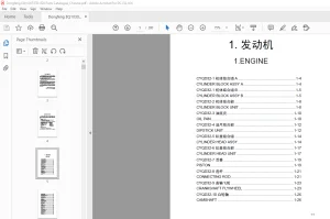
Engine74
Clutch75
Transmission76
Brake System76
Steering System77
Suspension System78
Propeller Shaft78
Axle and Wheel79
Others79
Main Adjusting Data80
Engine80
Chassis80
Fuel81
Grease Application Place and Schedule81
Lubricant and Vehicle Used Fluid82
Engine Lubricant83
Gear Oil84
Transmission Gear Oil84
Lubricating Grease84
Shock Absorber Oil84
Clutch Boost Liquid84
Engine Anti-freeze Fluid (cooling fluid)84
Capacity Data85
Tightening Torque86
Engine86
Chassis87
1 Battery89
2 Fusible wire89
3 Fusible wire89
4 Power switch89
5 Electronic main power switch89
6 Starter89
7 Starter relay89
8 Ignition switch89
9 Ignition relay89
10 Electric control engine cut-off89
11 Fuel cut-off electronic valve89
12 Clutch switch89
13 Exhaust brake electronic valve89
14 Throttle switch89
15 Exhaust brake switch89
16 Exhaust brake indicator89
17 Neutral switch89
18 Assist starting button89
19 Alternator89
20 Fuse89
21 Wiper motor89
22 Wiper switch89
23 Washer motor89
24 Wiper intermittent relay89
25 Fuse89
26 Cigar lighter89
27 Speaker89
28 Fuse89
29 Radio cassette89
30 Speaker89
31 Fuse89
32 Heater relay89
33 Heater motor89
34 Heater motor resistance89
35 Heater switch89
36 A/C switch89
37 Temperature control AMP89
38 A/C relay89
39 Dual direction pressure switch89
40 A/C compressor89
41 Heat emission relay89
42 Heat emission motor89
43 Fuse89
44 Dome lamp and Switch89
45 Left door switch89
46 Right door switch89
47 Horn button89
48 Fuse89
49 Horn relay89
50 Electric control dual tone air horn89
51 Electric horn89
52 Electric horn89
53 Air/electric horn shift switch89
54 Fuse89
55 Reverse gear switch89
56 Left reverse lamp89
57 Right reverse lamp89
58 Reverse buzzer89
59 Drier switch89
60 Drier89
61 Charging indicator89
62 Oil pressure warning sensor89
63 Oil pressure warning indicator89
64 Oil pressure gauge89
65 Oil pressure sensor90
66 Air flow blocked warning indicator90
67 Air flow blocked warning sensor90
68 Brake warning indicator90
69 Air pressure too low warning sensor90
70 Air pressure too low warning sensor90
71 Air pressure too low warning sensor90
72 Air pressure too low warning sensor90
73 Parking brake indicator90
74 Parking air pressure switch90
75 Fuel gauge90
76 Fuel sensor90
77 Water temperature gauge90
78 Water temperature sensor90
79 Water temperature warning indicator90
80 Tachometer90
81 Revolution sensor90
82 Combination switch–lighting part90
83 Low beam90
84 High beam90
85 Left headlamp90
86 Low beam90
87 High beam90
88 Right headlamp90
89 High beam indicator90
90 Left front lamp90
91 Right front lamp90
92 Front clearance lamp90
93 Front clearance lamp90
94 Rear clearane lamp90
95 Left side position lamp90
96 Fuse90
97 Fuse90
98 Fuse90
99 Rear clearance lamp90
100 Right side position lamp90
101 Licence lamp90
102 A/C control panel indicator90
103 Speedometer illuminator90
104 Instrumrnt illuminator90
105 Air pressure gauge illuminator90
106 Left front fog lamp90
107 Right front fog lamp90
108 Brake lamp switch90
109 Combination warning controller90
110 Left rear lamp90
111 Right rear lamp90
112 Left brake lamp90
113 Right brake lamp90
114 Left rear fog lamp90
115 Right rear fog lamp90
116 Safety belt indicator90
117 Filament check warning indicator90
118 Buzzer90
119 Door lamp switch90
120 Rear fog lamp indicator90
121 Rear fog lamp switch90
122 Fuse90
123 Quartz clock90
124 Hazard warning switch90
125 Fuse90
126 Flasher90
127 Combination switch-steering part90
128 Left turning lamp90
129 Left turning indicator90
Attached Drawing:89
Electric System Drawings89
S.M 20/2/2025