DOOSAN DX210WMH EXCAVATOR MATERIAL HANDER SHOP MANUAL 950106-01410NA – PDF DOWNLOAD
Original price was: $90.00.$29.95Current price is: $29.95.
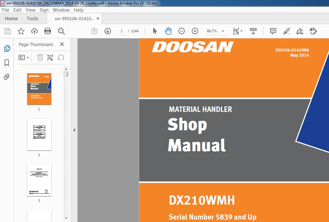
DOOSAN DX210WMH EXCAVATOR MATERIAL HANDER SHOP MANUAL 950106-01410NA – PDF DOWNLOAD
Serial Number 5839 and Up
Description
DOOSAN DX210WMH EXCAVATOR MATERIAL HANDER SHOP MANUAL 950106-01410NA – PDF DOWNLOAD
DESCRIPTION:
DOOSAN DX210WMH EXCAVATOR MATERIAL HANDER SHOP MANUAL 950106-01410NA – PDF DOWNLOAD
GENERAL
Safe Operation is Operator’s Responsibility
Only trained and authorized personnel should operate and maintain the machine.
Follow all safety rules, regulations and instructions when operating or performing maintenance on machine.
- • Do not operate machine if you are under the influence of drugs or alcohol.
- An operator who is taking prescription drugs must get medical advice to determine if he or she can safely operate a machine. •
- When working with other personnel on a work site, be sure that all personnel know nature of work and understand all hand signals that are to be used.
- • Be sure that all guards and shields are installed in their proper location. Have guards and shields repaired or replaced immediately if damaged. •
- Be sure that you understand the use and maintenance of all safety features such as safety lock lever and seat belt. Use them properly. •
- Never remove, modify or disable any safety features. Always keep them in good operating condition.
- • Always check for and know the location of underground and overhead utility lines before excavating
- . • Failure to use and maintain safety features according to instructions in this manual, Safety Manual and Shop Manual can result in death or serious injury.
Know Your Machine
Know how to operate your machine. Know the purpose of all controls, gauges, signals, indicators and monitor displays. Know the rated load capacity, speed range, braking and steering characteristics, turning radius and operating clearances. Keep in mind that rain, snow, ice, loose gravel, soft ground, slopes etc., can change operating capabilities of your machine.
TABLE OF CONTENTS:
DOOSAN DX210WMH EXCAVATOR MATERIAL HANDER SHOP MANUAL 950106-01410NA – PDF DOWNLOAD
sm-950106-01410 NA_DX210WMH_2014-05-20...................................................................................................................................................................................................................................... 0 Safety.................................................................................................................................................................................................................................................................. 9 Wheel Material Handler Maintenance Safety SP002195NA................................................................................................................................................................................................................ 11 Safety Precautions.............................................................................................................................................................................................................................................. 15 Applicable Models............................................................................................................................................................................................................................................... 15 Safety Messages................................................................................................................................................................................................................................................. 16 Signal Words................................................................................................................................................................................................................................................ 16 Safety Decals................................................................................................................................................................................................................................................... 17 General......................................................................................................................................................................................................................................................... 17 Safe Operation is Operator's Responsibility................................................................................................................................................................................................................. 17 Know Your Machine........................................................................................................................................................................................................................................... 17 Proper Work Tools and Attachments........................................................................................................................................................................................................................... 18 Pressurized Fluids.......................................................................................................................................................................................................................................... 18 Flying or Falling Objects................................................................................................................................................................................................................................... 19 Personal Protective Equipment (PPE)......................................................................................................................................................................................................................... 20 Correction of Machine Problems.............................................................................................................................................................................................................................. 20 Crushing and Cutting........................................................................................................................................................................................................................................ 20 Hot Coolant and Oils - Burn Prevention...................................................................................................................................................................................................................... 21 Fire and Explosion Prevention............................................................................................................................................................................................................................... 22 Fire Extinguisher and First-Aid Kit (Emergency Medical Kit)................................................................................................................................................................................................. 25 Electrical System and Electrical Shock...................................................................................................................................................................................................................... 26 Transportation.................................................................................................................................................................................................................................................. 29 Obey State and Local Over-the-Road Regulations.............................................................................................................................................................................................................. 29 Loading and Unloading....................................................................................................................................................................................................................................... 29 Transporting Machine........................................................................................................................................................................................................................................ 30 Operation....................................................................................................................................................................................................................................................... 31 Before Engine Starting...................................................................................................................................................................................................................................... 31 Work Site................................................................................................................................................................................................................................................... 32 Mounting/Dismounting........................................................................................................................................................................................................................................ 33 Cleaning.................................................................................................................................................................................................................................................... 34 Operator Station............................................................................................................................................................................................................................................ 34 Seat Belt................................................................................................................................................................................................................................................... 35 Visibility Information...................................................................................................................................................................................................................................... 36 Boost Starting or Charging Engine Batteries................................................................................................................................................................................................................. 37 Starting Engine............................................................................................................................................................................................................................................. 38 Swinging or Traveling....................................................................................................................................................................................................................................... 39 Lifting..................................................................................................................................................................................................................................................... 41 Towing...................................................................................................................................................................................................................................................... 42 Attachment.................................................................................................................................................................................................................................................. 43 Lowering Elevating Cab with Engine Stopped.................................................................................................................................................................................................................. 44 Engine Stop................................................................................................................................................................................................................................................. 44 Parking Machine............................................................................................................................................................................................................................................. 45 Service Brake............................................................................................................................................................................................................................................... 46 Preservation/Storing Machine................................................................................................................................................................................................................................ 47 Maintenance..................................................................................................................................................................................................................................................... 49 Cleaning.................................................................................................................................................................................................................................................... 53 Proper Tools and Clothing................................................................................................................................................................................................................................... 53 Disassembling Precautions................................................................................................................................................................................................................................... 53 Use of Lighting............................................................................................................................................................................................................................................. 54 Fire and Explosion Prevention............................................................................................................................................................................................................................... 54 Burn Prevention............................................................................................................................................................................................................................................. 55 Rubber That Contains Fluorides.............................................................................................................................................................................................................................. 56 Rubber and Plastics......................................................................................................................................................................................................................................... 57 Welding Repairs............................................................................................................................................................................................................................................. 58 Warning for Counterweight and Front Attachment Removal...................................................................................................................................................................................................... 59 Lock Inspection Covers...................................................................................................................................................................................................................................... 60 Working on Machine.......................................................................................................................................................................................................................................... 60 Accumulator................................................................................................................................................................................................................................................. 61 Compressed Air.............................................................................................................................................................................................................................................. 61 Supports and Blocking for Work Equipment.................................................................................................................................................................................................................... 61 High-pressure Lines, Tubes and Hoses........................................................................................................................................................................................................................ 62 Battery..................................................................................................................................................................................................................................................... 63 Environment and Circumstances................................................................................................................................................................................................................................... 65 Work Site Areas Requiring Extra Caution..................................................................................................................................................................................................................... 65 High-voltage Cables......................................................................................................................................................................................................................................... 66 Working in Water............................................................................................................................................................................................................................................ 67 Working in Contaminated Environment......................................................................................................................................................................................................................... 67 Operation in Extreme Conditions............................................................................................................................................................................................................................. 68 Exhaust Ventilation......................................................................................................................................................................................................................................... 72 Asbestos Information........................................................................................................................................................................................................................................ 72 Silica Dust Information..................................................................................................................................................................................................................................... 73 Disposal of Hazardous Materials............................................................................................................................................................................................................................. 73 Specifications.......................................................................................................................................................................................................................................................... 75 Specification SP000957NA............................................................................................................................................................................................................................................ 77 Safety Precautions.............................................................................................................................................................................................................................................. 81 Applicable Models............................................................................................................................................................................................................................................... 81 General Description............................................................................................................................................................................................................................................. 83 Component Locations............................................................................................................................................................................................................................................. 84 General Dimensions.............................................................................................................................................................................................................................................. 87 One - Piece Boom............................................................................................................................................................................................................................................ 87 Working Range................................................................................................................................................................................................................................................... 88 One - Piece Boom............................................................................................................................................................................................................................................ 88 General Specifications.......................................................................................................................................................................................................................................... 89 Hydraulic System Component Specifications....................................................................................................................................................................................................................... 90 System Component Specifications................................................................................................................................................................................................................................. 91 Performance Tests and Standards................................................................................................................................................................................................................................. 95 Material Handler Performance Standards.......................................................................................................................................................................................................................... 96 Test Conditions............................................................................................................................................................................................................................................. 96 Travel Speed Tests.......................................................................................................................................................................................................................................... 96 Swing Speed and Deceleration Force Test..................................................................................................................................................................................................................... 98 Cylinder Performance Tests.................................................................................................................................................................................................................................. 100 General Maintenance..................................................................................................................................................................................................................................................... 101 General Maintenance Procedures SP000016NA........................................................................................................................................................................................................................... 103 Safety Precautions.............................................................................................................................................................................................................................................. 107 Applicable Models............................................................................................................................................................................................................................................... 107 Welding Precautions and Instructions............................................................................................................................................................................................................................ 108 Hydraulic System - General Precautions.......................................................................................................................................................................................................................... 109 Maintenance Service and Repair Procedure........................................................................................................................................................................................................................ 111 General Precautions......................................................................................................................................................................................................................................... 111 Hydraulic System Cleanliness and Oil Leaks...................................................................................................................................................................................................................... 112 Maintenance Precautions for Hydraulic System Service........................................................................................................................................................................................................ 112 Oil Leakage Precautions..................................................................................................................................................................................................................................... 113 Cleaning and Inspection......................................................................................................................................................................................................................................... 114 General Instructions........................................................................................................................................................................................................................................ 114 Bearing Inspection.......................................................................................................................................................................................................................................... 115 Standard Torques SP000813NA......................................................................................................................................................................................................................................... 123 Safety Precautions.............................................................................................................................................................................................................................................. 127 Applicable Models............................................................................................................................................................................................................................................... 127 Torque Values for Standard Metric Fasteners..................................................................................................................................................................................................................... 128 Torque Values for Standard U.S. Fasteners....................................................................................................................................................................................................................... 129 Type 8 Phosphate Coated Hardware................................................................................................................................................................................................................................ 131 Torque Values for Hose Clamps................................................................................................................................................................................................................................... 132 Torque Values for Split Flanges................................................................................................................................................................................................................................. 133 Torque Wrench Extension Tools................................................................................................................................................................................................................................... 134 Torque Multiplication....................................................................................................................................................................................................................................... 134 Other Uses for Torque Wrench Extension Tools................................................................................................................................................................................................................ 135 Tightening Torque Specifications (Metric)................................................................................................................................................................................................................... 136 Upper Structure......................................................................................................................................................................................................................................................... 139 Cabin SP002191NA.................................................................................................................................................................................................................................................... 141 Safety Precautions.............................................................................................................................................................................................................................................. 145 Applicable Models............................................................................................................................................................................................................................................... 145 Counterweight SP002207NA............................................................................................................................................................................................................................................ 153 Safety Precautions.............................................................................................................................................................................................................................................. 157 Applicable Models............................................................................................................................................................................................................................................... 157 General......................................................................................................................................................................................................................................................... 158 Warning for Counterweight and Front Attachment Removal...................................................................................................................................................................................................... 158 Installation.................................................................................................................................................................................................................................................... 162 Fuel Tank SP002208NA................................................................................................................................................................................................................................................ 163 Safety Precautions.............................................................................................................................................................................................................................................. 167 Applicable Models............................................................................................................................................................................................................................................... 167 General Description............................................................................................................................................................................................................................................. 0 Specifications.............................................................................................................................................................................................................................................. 169 Fuel Transfer Pump SP000021NA....................................................................................................................................................................................................................................... 179 Safety Precautions.............................................................................................................................................................................................................................................. 183 Applicable Models............................................................................................................................................................................................................................................... 183 Troubleshooting................................................................................................................................................................................................................................................. 186 Replacement of Rotor and Vane................................................................................................................................................................................................................................... 186 Swing Bearing SP001869NA............................................................................................................................................................................................................................................ 189 Safety Precautions.............................................................................................................................................................................................................................................. 193 Applicable Models............................................................................................................................................................................................................................................... 193 Swing Bearing Maintenance....................................................................................................................................................................................................................................... 194 Operating Recommendation.................................................................................................................................................................................................................................... 194 Measuring Swing Bearing Axial Play.......................................................................................................................................................................................................................... 194 Measuring Bearing Lateral Play.............................................................................................................................................................................................................................. 194 Swing Bearing Basic Operation............................................................................................................................................................................................................................... 195 Disassembly................................................................................................................................................................................................................................................. 195 Assembly.................................................................................................................................................................................................................................................... 197 1. Clean (degrease) the seal groove for the outer and inner seals (7)................................................................................................................................................................................... 197 2. Hoist the outer race by crane horizontally and match it with the inner race coaxially................................................................................................................................................................ 197 3. Top plug (4) into outer race (1) and then, drive pin (3) into the pin hole........................................................................................................................................................................... 197 Swing Reduction Gear SP002204NA..................................................................................................................................................................................................................................... 199 Safety Precautions.............................................................................................................................................................................................................................................. 203 Applicable Models............................................................................................................................................................................................................................................... 203 General Description............................................................................................................................................................................................................................................. 205 Theory of Operation......................................................................................................................................................................................................................................... 205 Parts List.................................................................................................................................................................................................................................................. 206 Specifications.............................................................................................................................................................................................................................................. 207 Disassembly..................................................................................................................................................................................................................................................... 210 1. Remove bolts and motor from swing reduction case......................................................................................................................................................................................................... 210 2. Remove No. 1 sun gear from No. 1 carrier................................................................................................................................................................................................................. 210 3. Remove No. 1 carrier..................................................................................................................................................................................................................................... 211 4. Remove washer and No. 2 sun gear......................................................................................................................................................................................................................... 211 5. Remove bolt in No. 2 carrier............................................................................................................................................................................................................................. 212 6. Install eye bolts in No. 2 carrier and remove it from ring gear.......................................................................................................................................................................................... 212 7. Install eye bolts in ring gear and remove it............................................................................................................................................................................................................. 213 8. Use a rollover machine to turn assembly over............................................................................................................................................................................................................. 214 9. Remove cover plate....................................................................................................................................................................................................................................... 214 10. Use a rollover machine to turn case over and place a jig on drive shaft. Use a press to remove drive shaft from case.................................................................................................................................... 215 11. Remove bearing from case................................................................................................................................................................................................................................ 215 12. Put drive shaft in press, and remove bearing and spacer................................................................................................................................................................................................. 216 Cleaning and Inspection (Wear Limits and Tolerances)............................................................................................................................................................................................................ 216 Reassembly...................................................................................................................................................................................................................................................... 217 Shaft and S/R Bearing Heat-fit.............................................................................................................................................................................................................................. 217 Assembly of Carrier Subassemblies........................................................................................................................................................................................................................... 219 1. Put No. 1 carrier on assembly jig as shown in Figure 29.............................................................................................................................................................................................. 219 2. Assemble the pin ass,y 1 and the washer into planet gear 1 and arrange it on the pin hole of the carrier 1........................................................................................................................................... 219 3. Put the jig, while keeping the pin assembly 1 perpendicular, and push it with a press................................................................................................................................................................ 220 4. After its pressure insert, check the state of the pressure insert visually........................................................................................................................................................................... 220 5. Insert the 2 remaining parts with pressure in the same way........................................................................................................................................................................................... 221 6. Engage the snap ring (for .ı 38 axis) to each thread of the pin 1 and check if gear turns smooth by turning it....................................................................................................................................... 221 1. Put No. 2 carrier on assembly jig as shown in Figure 39.............................................................................................................................................................................................. 222 2. Insert No. 2 bushing into No. 2 planetary gear, and position a No. 2 thrust washer on it............................................................................................................................................................. 222 3. Turn over gear assembly and insert it into No. 2 carrier. Align bushing hole with carrier holes...................................................................................................................................................... 222 4. Align spring pin hole in No. 2 shaft with spring pin hole of No. 2 carrier. Insert shaft into carrier and No. 2 bushing.............................................................................................................................. 223 5. Install three remaining No. 2 gears in same manner................................................................................................................................................................................................... 223 6. After all four shafts are installed, align spring pin (.ı 10x25L) with carrier hole and drive it into position using a hammer........................................................................................................................ 223 7. Using a hammer and punch, calking spring pin into position........................................................................................................................................................................................... 224 8. Repeat procedure for other three spring pins. Make sure that gears properly rotate................................................................................................................................................................... 224 Assembly of Main Case....................................................................................................................................................................................................................................... 225 1. Insertion of shaft subassembly:...................................................................................................................................................................................................................... 225 A. Set gear case as shown in Figure 51.............................................................................................................................................................................................................. 225 B. Using a suitable lifting device, lower shaft subassembly into case............................................................................................................................................................................... 225 C. Using special jig, keep bearing level and press it into case..................................................................................................................................................................................... 225 1. Position case so that pinion gear is pointing down................................................................................................................................................................................................... 226 2. Make sure that there is no foreign substance left on seal assembly, apply grease to and around lip of oil seal (TC5001300) as in Figure 59 and Loctite #609 to its external part..................................................................... 227 3. Using seal installation jig, press seal into case, keeping it level during installation. Make sure that seal is fully seated......................................................................................................................... 227 4. Using seal installation jig, position bearing on end of shaft, with bearing trade mark on inner race facing up. Press bearing firmly into place, making sure it is properly seated................................................................... 229 5. Rotate pinion by hand and check if it turns properly................................................................................................................................................................................................. 230 6. Install plugs into PT1/2 and PT1/4 drain ports....................................................................................................................................................................................................... 230 1. Insertion of lock pin................................................................................................................................................................................................................................ 231 2. Apply liquid gasket (Three Bond #1104) evenly to ring gear assembly of casing........................................................................................................................................................................ 231 3. Lift ring gear with hoist, wipe its mating surface clean with cloth, match and align holes after checking its assembling direction, and press assembled parts firmly by tightening special bolts (M12x150) on which no Loctite has been applied...... 232 1. Using a suitable lifting device, lower No. 2 carrier assembly into ring gear, making sure that planetary gears are engaged. Continue to lower carrier and engaging it onto splines of pinion shaft. Make sure that carrier is resting on bearing..... 232 2. Place a tongued washer on the thrust washer 3 of the carrier assembly 2 and engage a hexagon bolt (M16x25L, torque: 3,000kgf.cm) applied Loctite (#262) with it...................................................................................... 233 3. After tightening the bolt, fix the carrier assembly 2 and use a torque wrench to tighten it up to the standard torque. After checking the torque, bend the longer part of the tongued washer until it sticks to the head of the hexagon bolt......... 234 4. Install No. 2 sun gear in No. 2 carrier.............................................................................................................................................................................................................. 234 5. Lift the carrier assembly 1, and turn it clockwise or anticlockwise gently for it to engage with the spline of the sun gear 2 and the ring gear...................................................................................................... 234 6. Assemble the sun gear 1.............................................................................................................................................................................................................................. 235 1. Remove the compression bolts of the ring gear, wipe out the motor assembly with clean cloth, and apply liquid (#1104) gasket evenly.................................................................................................................. 236 2. Use a hoist to lift the prepared motor, wipe out the assembly, and engage the snap ring on the shaft................................................................................................................................................. 236 3. Put the motor on the reduction gear carefully with the adjustment of its direction as shown in the figure below (care should ........................................................................................................................ 236 4. Apply Loctite (#2652) to 16 socket bolts (M12x150L, torque: 1,440 kgf.cm), insert into holes, and tighten with an impact wrench...................................................................................................................... 237 5. Engage the level gauge pipe sealed with Teflon tape to the level gauge port of the port with a pipe wrench........................................................................................................................................... 238 1. Open the oil inlet lid and supply gear oil (EP80W/90) of 3.8ߧ....................................................................................................................................................................................... 239 2. After the supply of oil, stick the level gauge into tank and check the oil level..................................................................................................................................................................... 239 3. Put the nipple to supply grease in the PT1/4 tap hole and start to supply grease until it flows out of the opposite PT1/ 4 hole...................................................................................................................... 240 4. After the completion of supplying grease, release and remove cokes, assemble the PT1/4 plug sealed with Teflon tape (torque: ........................................................................................................................ 240 Installation.................................................................................................................................................................................................................................................... 242 Start-up Procedures............................................................................................................................................................................................................................................. 242 Lower Structure and Chassis............................................................................................................................................................................................................................................. 243 Ram Lock Valve SP000923NA........................................................................................................................................................................................................................................... 245 Safety Precautions.............................................................................................................................................................................................................................................. 249 Applicable Models............................................................................................................................................................................................................................................... 249 Sectional Drawing and Part Names................................................................................................................................................................................................................................ 250 Hydraulic Circuit............................................................................................................................................................................................................................................... 250 Operational Principle........................................................................................................................................................................................................................................... 251 In Case of No Pilot Pressure at PI Port..................................................................................................................................................................................................................... 251 In Case of Pilot Pressure (Approx. 20 kg.cm2) at PI Port.................................................................................................................................................................................................... 251 Disassembly and Assembly........................................................................................................................................................................................................................................ 251 General Cautions............................................................................................................................................................................................................................................ 251 Assembly and Disassembly of Chocking Valve.................................................................................................................................................................................................................. 252 Performance Test................................................................................................................................................................................................................................................ 253 Oil Leakage Test............................................................................................................................................................................................................................................ 253 Operational Test............................................................................................................................................................................................................................................ 253 Selector Valve SP000926NA........................................................................................................................................................................................................................................... 255 Safety Precautions.............................................................................................................................................................................................................................................. 259 Applicable Models............................................................................................................................................................................................................................................... 259 Sectional Drawing and Part Names................................................................................................................................................................................................................................ 260 Hydraulic Circuit............................................................................................................................................................................................................................................... 260 Operational Principle........................................................................................................................................................................................................................................... 261 Neutral Position: A Æ B..................................................................................................................................................................................................................................... 261 Selective Position: A Æ C................................................................................................................................................................................................................................... 261 Disassembly and Assembly........................................................................................................................................................................................................................................ 262 General Cautions............................................................................................................................................................................................................................................ 262 Assembly and Disassembly of Selector Valve.................................................................................................................................................................................................................. 262 Performance Test................................................................................................................................................................................................................................................ 264 Oil Leakage Test............................................................................................................................................................................................................................................ 264 Operational Test............................................................................................................................................................................................................................................ 264 Double Pilot Check Valve SP000927NA................................................................................................................................................................................................................................. 265 Safety Precautions.............................................................................................................................................................................................................................................. 269 Applicable Models............................................................................................................................................................................................................................................... 269 Sectional Drawing & Parts....................................................................................................................................................................................................................................... 270 Hydraulic Diagram............................................................................................................................................................................................................................................... 271 Operational Principle........................................................................................................................................................................................................................................... 272 A Æ C, D Æ B................................................................................................................................................................................................................................................ 272 B Æ D, C Æ A................................................................................................................................................................................................................................................ 272 Disassembly and Assembly........................................................................................................................................................................................................................................ 273 General Cautions............................................................................................................................................................................................................................................ 273 Assembly and Disassembly of Double Pilot Check Valve........................................................................................................................................................................................................ 274 Performance Test................................................................................................................................................................................................................................................ 276 Cracking Pressure Test for Check Cartridge Ass'y............................................................................................................................................................................................................ 276 Pilot Cracking Pressure Test................................................................................................................................................................................................................................ 276 Oil Leakage Test............................................................................................................................................................................................................................................ 277 Solenoid Valve SP000928NA........................................................................................................................................................................................................................................... 279 Safety Precautions.............................................................................................................................................................................................................................................. 283 Applicable Models............................................................................................................................................................................................................................................... 283 Single Solenoid Valve Diagram................................................................................................................................................................................................................................... 284 Functions of Single Solenoid Valve.............................................................................................................................................................................................................................. 285 Functions of Each Valve..................................................................................................................................................................................................................................... 285 Disassembly and Reassembly Diagrams............................................................................................................................................................................................................................. 286 Troubleshooting of Each Part.................................................................................................................................................................................................................................... 287 Double Solenoid Valve Diagram................................................................................................................................................................................................................................... 288 Functions of Double Solenoid Valve.............................................................................................................................................................................................................................. 289 Functions of Each Valve..................................................................................................................................................................................................................................... 289 Disassembly and Reassembly Diagrams............................................................................................................................................................................................................................. 290 Troubleshooting of Each Part.................................................................................................................................................................................................................................... 291 Front Axle SP000929NA............................................................................................................................................................................................................................................... 293 Safety Precautions.............................................................................................................................................................................................................................................. 297 Applicable Models............................................................................................................................................................................................................................................... 297 Examples of Gear-Tooth-Contact Patterns for the Gleason Gear-Tooth System................................................................................................................................................................................... 298 Lubrication and Maintenance Specifications for Axle MS- E 3050/3060/3070........................................................................................................................................................................................ 300 1. Oil Drain From Axle...................................................................................................................................................................................................................................... 300 2. Oil Drain From Outputs................................................................................................................................................................................................................................... 300 3. Oil Filling of Axle...................................................................................................................................................................................................................................... 301 Tightening torque (M36x1.5) MA = 50 N.m................................................................................................................................................................................................................. 301 4. Check.................................................................................................................................................................................................................................................... 301 Tightening torque (M36x1.5) MA = 50 N.m................................................................................................................................................................................................................. 301 Tightening torque (M36x1.5) MA = 50 N.m................................................................................................................................................................................................................. 301 1. Motor oils SAE 10 W acc. to specification MIL-L 2104 C, MIL-L 46152, API-CC, CD, SC, SD, SE.............................................................................................................................................................. 301 2. ATF. oils type A, Suffic A, Dexron von II D.............................................................................................................................................................................................................. 301 Brake Wear Measurement on Axles of MT/MS-E 3050/ 3060/3070 Range................................................................................................................................................................................................ 302 Tightening torque(M36x1.5) MA = 50 N.m...................................................................................................................................................................................................................... 303 Disassembly..................................................................................................................................................................................................................................................... 304 Steering.................................................................................................................................................................................................................................................... 304 1. View - Steering installed in axle.................................................................................................................................................................................................................... 304 2. Loosen hex nuts on both tie rods..................................................................................................................................................................................................................... 304 4. Separate both tie rods (ass’y) from piston rod....................................................................................................................................................................................................... 305 5. Disassemble both elbows (see arrows) or screw necks, depending on version............................................................................................................................................................................ 305 6. Loosen threaded joint of steering / axle drive housing............................................................................................................................................................................................... 306 7. Steering cylinder is fixed with locking compound - disassembly is more difficult!.................................................................................................................................................................... 306 8. Drive out steering cylinder ass’y from axle drive housing by means of a plastic / aluminium hammer................................................................................................................................................... 306 9. Unsnap the circlip and remove flange................................................................................................................................................................................................................. 306 10. Unsnap retaining ring............................................................................................................................................................................................................................... 307 11. Drive the guide into the cylinder tube (direction of arrow) until the circlip can be removed (see Figure 26)........................................................................................................................................ 307 12. Unsnap circlip...................................................................................................................................................................................................................................... 307 13. Drive out piston rod together with guide from cylinder tube......................................................................................................................................................................................... 307 14. Pull off guide from piston rod...................................................................................................................................................................................................................... 308 Output...................................................................................................................................................................................................................................................... 308 1. Loosen screw plug and drain oil from the axle........................................................................................................................................................................................................ 308 2. Please take the required work steps (such as dismantling the tie rod-, bearing pins ecc. ...) from chapters.......................................................................................................................................... 309 1. Loosen both cylinder screws and separate planetary carrier from hub.................................................................................................................................................................................. 309 2. Unsnap circlip....................................................................................................................................................................................................................................... 309 3. Pull off planetary gear by means of a two-armed puller............................................................................................................................................................................................... 309 4. Unsnap circlip and remove washer..................................................................................................................................................................................................................... 310 1. Unsnap retaining ring and remove both thrust washers................................................................................................................................................................................................. 310 2. Remove slotted nut mount (cylinder screw)............................................................................................................................................................................................................ 310 3. Loosen slotted nut................................................................................................................................................................................................................................... 310 4. Press off ring gear with piston...................................................................................................................................................................................................................... 311 5. Loosen hex. screws, remove spring sleeves and compression springs.................................................................................................................................................................................... 311 6. Press off piston from ring gear...................................................................................................................................................................................................................... 311 7. Remove sealing elements (arrows) from ring gear...................................................................................................................................................................................................... 311 8. Remove plate pack.................................................................................................................................................................................................................................... 312 9. Remove O-ring (arrow) and lift-off disc carrier with lever, then remove releasing O-ring............................................................................................................................................................. 312 10. Pull hub from hub carrier by means of pressure piece and two armed puller........................................................................................................................................................................... 312 11. Lift-off shaft seal (arrow) with lever and remove both bearing outer rings from hub................................................................................................................................................................. 312 12. Just for axle type MS-E 3060 :...................................................................................................................................................................................................................... 313 13. Pull bearing inner ring from hub.................................................................................................................................................................................................................... 313 1. Legend to the sketch................................................................................................................................................................................................................................. 313 2. Loosen threaded connection and remove upper bearing pin.............................................................................................................................................................................................. 313 3. Secure knuckle housing by means of lifting device and dismantle lower bearing pin.................................................................................................................................................................... 314 4. Remove bearing inner ring (7), O-ring (5), sealing cap (6) and brake connection screw neck (8) from bearing pin (1).................................................................................................................................. 314 5. Separate knuckle housing with double u-joint shaft from axle housing................................................................................................................................................................................. 314 6. Pull out double u-joint shaft from knuckle housing................................................................................................................................................................................................... 314 7. Pull out seal ring and afterwards the bushing behind from the knuckle housing........................................................................................................................................................................ 315 8. Pull out seal ring and afterwards the bushing behind from the axle housing........................................................................................................................................................................... 315 9. Pull out both bearing outer rings from the swivel bearing holes...................................................................................................................................................................................... 315 Differential - Input........................................................................................................................................................................................................................................ 316 1. Fix axle housing part / II by means of a lifting strap, loosen threaded joint of axle housing half on crown wheel side (differential) and separate axle housing half part / II from axle drive housing............................................... 316 2. Remove bearing outer ring (arrow1) and the shim behind as well as O ring (arrow 2) from axle housing part / II....................................................................................................................................... 316 3. Lift off the differential from the axle drive housing................................................................................................................................................................................................ 317 4. Pull out bearing outer ring and the shim behind from the bearing hole of axle housing part / I....................................................................................................................................................... 317 1. The illustration shows version "D-500"............................................................................................................................................................................................................... 317 2. Loosen threaded joint (position "X")................................................................................................................................................................................................................. 317 A. Version "D-500".................................................................................................................................................................................................................................. 318 B. Version "D-750".................................................................................................................................................................................................................................. 318 1. Legend to Figure 69.................................................................................................................................................................................................................................. 319 4. Lift-off seal ring with lever........................................................................................................................................................................................................................ 320 5. Drive out input pinion............................................................................................................................................................................................................................... 320 6. Remove spacer ring................................................................................................................................................................................................................................... 320 7. Press off bearing inner ring from input pinion....................................................................................................................................................................................................... 320 8. Extract outside bearing outer ring................................................................................................................................................................................................................... 321 9. Drive out bearing outer ring from the inner bearing hole - pay attention to the shim behind.......................................................................................................................................................... 321 Pivot Bearing............................................................................................................................................................................................................................................... 321 Reassembly...................................................................................................................................................................................................................................................... 322 Input....................................................................................................................................................................................................................................................... 322 Tightening torque MA = 390 N.m (M 18/10.9).............................................................................................................................................................................................................. 322 1. Read dimension "I" (Position - see arrow) from axle drive housing.................................................................................................................................................................................... 322 Dimension "I" e.g 149.09 mm......................................................................................................................................................................................................................... 322 2. Read pinion dimension (basic distance) "X" from pinion (see arrow) or measure it in case of a + or - deviation of the pinion dimension caused by the production (value concerned is marked by hand on the pinion, e.g.+ 0.1)......................... 323 Dimension "II" (Pinion basic distance) e.g. 116.00 mm............................................................................................................................................................................................... 323 3. Since the installed roller bearing is subject to a pre-load in installation position, consider an experience deduction of - 0.1mm!................................................................................................................... 323 Dimension "I" 149.09 mm............................................................................................................................................................................................................................. 323 Dimension "II + III" (116.00 + 31.90) -148.10 mm.................................................................................................................................................................................................... 323 Result = 1.01 mm.................................................................................................................................................................................................................................... 323 Shim required "S" 1.00 mm........................................................................................................................................................................................................................... 323 4. Insert the determined shim (e.g. "S" = 1.00 mm) into the inner bearing hole / pinion bearing......................................................................................................................................................... 323 5. Super-cool bearing outer ring (see arrow) and bring it into contact position in the inner bearing hole / pinion bearing by means of the fixture...................................................................................................... 324 6. Instal outside bearing outer ring / pinion bearing................................................................................................................................................................................................... 324 7. Mount heated bearing inner ring until contact is obtained and readjust after cooling-down............................................................................................................................................................ 324 1. Mount spacer ring (s = optional)..................................................................................................................................................................................................................... 324 2. Insert the preassembled drive pinion, mount the heated bearing inner ring until contact is obtained.................................................................................................................................................. 325 3. Mount flange, fix with washer and hex. nut........................................................................................................................................................................................................... 325 Tightening torque (M27x1.5) MA = 600 N.m............................................................................................................................................................................................................ 325 4. Check rolling moment of pinion bearing............................................................................................................................................................................................................... 325 1. Illustration shows version "D-500"................................................................................................................................................................................................................... 326 2. Assembly Specification:.............................................................................................................................................................................................................................. 326 3. Press differential carrier until contact is obtained................................................................................................................................................................................................. 326 4. Insert thrust washer and axle bevel gear............................................................................................................................................................................................................. 326 5. Install differential bevel gears and thrust washers on differential spider and insert in differential carrier half I................................................................................................................................. 327 6. Insert second axle bevel gear........................................................................................................................................................................................................................ 327 7. Stick thrust washer with grease (assembly aid) into differential carrier half II..................................................................................................................................................................... 327 8. Fasten differential carrier halves with cylinder. screws and washers (D-500, Pos. X) and with hex. screws (D-750, Pos.X)............................................................................................................................. 327 A. Version "D-500".................................................................................................................................................................................................................................. 328 B. Version "D-750".................................................................................................................................................................................................................................. 328 Tightening torque (M 12x1.5/12.9) MA = 145 N.m.................................................................................................................................................................................................. 328 Tightening torque (M 12x1.5/10.9) MA = 122 N.m.................................................................................................................................................................................................. 328 Tightening torque (M 16x1.5/10.9) MA = 300 N.m.................................................................................................................................................................................................. 328 9. Wet some tooth flanks of the crown wheel with marking ink (for contact pattern check - See Figure 112 on page -40)................................................................................................................................... 328 1. Insert shim (backlash) into hole of axle housing / part I and install bearing outer ring until contact is obtained................................................................................................................................... 329 2. Insert pre-assembled differential.................................................................................................................................................................................................................... 329 3. Place bearing outer ring............................................................................................................................................................................................................................. 329 4. Determine dimension "I", from mounting face of axle drive housing to bearing contact................................................................................................................................................................. 330 Dimension "I" e.g. 18.10 mm......................................................................................................................................................................................................................... 330 5. Determine dimension "II", from mounting face of axle housing part II to contact face / bearing outer ring............................................................................................................................................ 330 Dimension "II" e.g. 17.20 mm........................................................................................................................................................................................................................ 330 Dimension "I" e.g. 18.10 mm......................................................................................................................................................................................................................... 330 Dimension "II" e.g. - 17.20 mm...................................................................................................................................................................................................................... 330 Difference = 0.90 mm................................................................................................................................................................................................................................ 330 requ. bearing preload (0.10 ~ 0.15mm) + 0.13 mm..................................................................................................................................................................................................... 330 Result = 1.03 mm.................................................................................................................................................................................................................................... 330 Required shim "S" Æ = 1.05 mm....................................................................................................................................................................................................................... 330 6. Insert determined shim(s) e.g. "S" = 1.05 mm into bearing hole of axle housing / part II and instal bearing outer ring so that contact is obtained................................................................................................... 331 7. Locate preassembled axle housing /part II (without O-ring) (observe radial installation position) and temporarily fix with hex. screws............................................................................................................... 331 1. Place dial indicator at right angles to a tooth flank of the crown wheel (within the outer diameter area) through oil drain hole and check backlash.................................................................................................. 331 Backlash................................................................................................................................................................................................................................................ 331 2. Rotate drive pinion in both directions several times over crown wheel / differential (contact pattern impression - in this connection see Figure 112)............................................................................................ 332 3. Remove differential.............................................................................................................................................................................................................................. 332 4. Oil O-ring and mount on collar (arrow) of axle housing half / part II............................................................................................................................................................................ 332 5. Reinstall differential........................................................................................................................................................................................................................... 333 6. Instal pre-assembled axle housing half (observe radial installation position), fix with hex. screws and washers.................................................................................................................................. 333 Tightening torque (M18/10.9) MA = 390 N.m....................................................................................................................................................................................................... 333 7. Disassemble flange............................................................................................................................................................................................................................... 333 Input Flange................................................................................................................................................................................................................................................ 334 1. Place seal ring (6), considering the required installation position (dimension "X") - see Figure 118................................................................................................................................................. 334 2. Press screen / thrust plate (5) on the input flange until contact is obtained - also see Figure 118.................................................................................................................................................. 335 3. Install pre-assembled input flange (4+5) and washer (3), fix with hex. nut (2)....................................................................................................................................................................... 335 Tightening torque (M27x1.5) MA = 600 N.m............................................................................................................................................................................................................ 335 Output...................................................................................................................................................................................................................................................... 335 1. Comment on Figure 122................................................................................................................................................................................................................................ 335 2. Mount just for cpl. output - Figure 123.............................................................................................................................................................................................................. 335 1. Legend on Figure 124 ~ Figure 128.................................................................................................................................................................................................................... 336 2. Flush-mount bushing in the axle housing hole, considering the installation position (see detailed sketch)............................................................................................................................................ 336 3. Flush-mount seal ring (item 3 - See Figure 124) into axle housing hole, with seal lip showing to oil chamber......................................................................................................................................... 336 4. Mount both bearing outer rings (Item 4- See Figure 124) into pivot bearing holes of the axle housing................................................................................................................................................. 337 1. Just for assembly of a new knuckle housing (Figure 130):............................................................................................................................................................................................. 337 2. Legend to Figure 131 ... Figure 134:................................................................................................................................................................................................................. 338 3. Flush-mount bushing into knuckle housing hole, considering the installation position (See Figure 131 and detailed sketch)............................................................................................................................ 338 4. Mount seal ring (item 3 - See Figure 131) into knuckle housing hole - considering installation dimension "E" (See Figure 131) and installation position (seal lip showing to oil chamber)............................................................ 338 5. Legend to Figure 136 .... Figure 139:................................................................................................................................................................................................................ 339 6. Mount sealing cap.................................................................................................................................................................................................................................... 340 7. Instal O-ring (arrow - 1) and apply anti-corrosive agent, "Weicon Anti Seize" (Never Seez) ZF-order no. 0671 196001 on bearing pin collar (arrow-2).................................................................................................. 340 8. Just on lower bearing pin:........................................................................................................................................................................................................................... 340 9. Instal pre-assembled lower bearing pin and fix with hex. screws...................................................................................................................................................................................... 340 10. Instal O-ring....................................................................................................................................................................................................................................... 341 11. Instal pre-assembled upper bearing pin (Figure 137 and Figure 138).................................................................................................................................................................................. 341 12. Fix both bearing pins definitively.................................................................................................................................................................................................................. 341 Tightening torque (M 16/10.9) MA = 280 N.m.......................................................................................................................................................................................................... 341 13. Mount lubrication nipple (arrow-I) in both bearing pins and provide pivot bearing with grease (grease acc. to ZF- lubrication list "TE-ML 05", e.g. RENOLIT 283 EP 2)............................................................................... 341 Tightening torque (M 6xl) MA = 6 N.m................................................................................................................................................................................................................ 341 Tightening torque (M l4x1.5) MA = 35N.m............................................................................................................................................................................................................. 341 Tightening torque (M l4x1.5) MA = 20N.m............................................................................................................................................................................................................. 341 14. Check rolling moment of pivot bearing............................................................................................................................................................................................................... 342 1. Install heated bearing inner ring until contact is obtained.......................................................................................................................................................................................... 342 2. Just for axle type MS-E 3060:........................................................................................................................................................................................................................ 343 3. Mount wheel bolts (l)................................................................................................................................................................................................................................ 343 4. Mount shaft seal, considering installation position (marking OUT - SIDE looking upward / outward) and installation dimension "X" - see detailed sketch............................................................................................... 343 A. Version MT-E 3050/3060........................................................................................................................................................................................................................... 343 B. Version MT-E 3070................................................................................................................................................................................................................................ 344 5. Install preassembled hub until contact is obtained and fix with heated outer bearing inner ring...................................................................................................................................................... 344 6. Oil a-rings and locate in annular groove (arrow) of knuckle housing.................................................................................................................................................................................. 344 7. Bring hub bearing into contact position (Figure 155 ~ 157):.......................................................................................................................................................................................... 345 8. Bring hub bearing into contact position - for this purpose tighten slotted nut with a tightening torque of max. 1400 N.m............................................................................................................................. 345 9. Loosen slotted nut again and remove ring gear........................................................................................................................................................................................................ 345 1. Install disc pack alternately starting with an outer disc............................................................................................................................................................................................ 346 2. Installation position of inner discs:................................................................................................................................................................................................................ 346 3. Oil O-ring and locate in annular groove of disc carrier.............................................................................................................................................................................................. 346 4. Oil sealing elements and locate in annular grooves (arrows) of the ring gear - as shown in the detailed sketch....................................................................................................................................... 347 5. Just for "assembly of new parts" or if disassembled:................................................................................................................................................................................................. 347 6. Install piston on preassembled ring gear............................................................................................................................................................................................................. 347 Tightening torque (M 6/8.8) MA = 11 N.m............................................................................................................................................................................................................. 348 7. Mount preassembled ring gear considering the installation position (markings 0 in 12 o’clock position - see arrows, detail "B")...................................................................................................................... 348 8. Oil O-ring and insert in recess (arrow).............................................................................................................................................................................................................. 349 9. Fix ring gear with slotted nut....................................................................................................................................................................................................................... 349 Make Leakage Test of Multi-disc Brake................................................................................................................................................................................................................... 349 Adjust and Check Disc Clearance/Piston Stroke........................................................................................................................................................................................................... 350 Build up braking pressure (100 bar) and find dimension "A", from face / ring gear (1) through measuring hole (2) - See Figure 172 and Figure 173 - to face / piston (3)............................................................................. 350 Dimension "A" e.g. = 83.50 mm....................................................................................................................................................................................................................... 350 Dimension "B" e.g. = 82.10 mm....................................................................................................................................................................................................................... 350 Dimension "A" e.g. 83.50 mm......................................................................................................................................................................................................................... 350 Dimension "B" e.g. - 82.10 mm....................................................................................................................................................................................................................... 350 Result Æ disc clearance = 1.40 mm................................................................................................................................................................................................................... 350 Tightening torque (M 14 x 1.5) MA = 23 N.m.......................................................................................................................................................................................................... 351 Tightening torque (M 10/8.8) MA = 32 N.m............................................................................................................................................................................................................ 351 1. Determine dimension I from mounting face of planetary carrier to contact face of thrust washer................................................................................................................................................... 352 Dimension I, e.g. 260.65 mm..................................................................................................................................................................................................................... 352 2. Determine dimension II, from face (arrow) of sun gear to mounting face of hub.................................................................................................................................................................... 352 Dimension II, e.g. 255.70 mm.................................................................................................................................................................................................................... 352 Dimension I e.g. 260.65 mm...................................................................................................................................................................................................................... 352 Dimension II e.g. - 255.70 mm................................................................................................................................................................................................................... 352 Difference. 4.95 mm............................................................................................................................................................................................................................. 352 Required axial play (average) e.g. - 0.65 mm.................................................................................................................................................................................................... 352 Result = requir.thrust washer(s) e.g. s = 4.30 mm............................................................................................................................................................................................... 352 3. Insert thrust washer(s) (e.g. s = 4.30 mm) into planetary carrier and press into contact position................................................................................................................................................ 352 4. Preassemble planetary gear - depending on version - as shown in the figure beside................................................................................................................................................................ 352 5. Warm up bearing inner ring and install pre-assembled planetary gear until contact is obtained.................................................................................................................................................... 353 6. Fix planetary gear by means of retaining ring.................................................................................................................................................................................................... 353 7. Install preassembled planetary carrier and fix with cylinder screws.............................................................................................................................................................................. 353 Tightening torque (MI2/8.8) MA = 55 N.m......................................................................................................................................................................................................... 353 8. Install screw plug with new O-ring............................................................................................................................................................................................................... 354 Tightening torque (M 36 x 1.5) MA = 50 N.m...................................................................................................................................................................................................... 354 Pivot Bearing............................................................................................................................................................................................................................................... 354 Steering.................................................................................................................................................................................................................................................... 355 1. Mount U-ring (6) and wiper (7) in the steering cylinder (l).......................................................................................................................................................................................... 355 2. Position inner installer (S1) on piston rod (3), install O-ring (4b) and press with inner installer (S2) into annular groove (arrow) of piston (3)................................................................................................... 356 3. Install form seal ring (4a) and press with inner installer (S2) into annular groove (arrow) of piston (3)............................................................................................................................................ 356 4. Calibrate form seal ring (4a) by means of calibration bush (S3)...................................................................................................................................................................................... 357 5. Place both guide rings (5) into annular grooves of the piston rod.................................................................................................................................................................................... 357 6. Insert preassembled piston rod in the preassembled steering cylinder................................................................................................................................................................................. 357 7. Insert u-ring(6), rod wiper (7) and dual ring (8) in brake head(2)................................................................................................................................................................................... 358 8. Install preassembled brake head...................................................................................................................................................................................................................... 358 9. Push brake head into the steering cylinder (arrow) so that the circlip (9) can be mounted............................................................................................................................................................ 358 10. Bring the inserted brake head (8) into contact position (arrow) on the snapped circlip (9).......................................................................................................................................................... 359 11. Fix brake head (8) with retaining ring (11)......................................................................................................................................................................................................... 359 12. Install flange (12) and snap circlip (13)........................................................................................................................................................................................................... 359 13. Provide both contact faces (steering cylinder/axle drive housing) with sealing agent (Loctite-Nr. 574).............................................................................................................................................. 359 14. Insert preassembled steering cylinder and fix with hex. screws...................................................................................................................................................................................... 360 Tightening torque (M 12/8.8) MA = 79 N.m............................................................................................................................................................................................................ 360 15. If required - preassemble both tie rods............................................................................................................................................................................................................. 360 16. Do not tighten the screw of the clamp before setting the track...................................................................................................................................................................................... 360 Tightening torque (M 12x1.5) MA = 75 N.m............................................................................................................................................................................................................ 360 17. Provide connection - axial joint/piston rod (appr. 3 threads)- with locking agent (Loctite-no. 243)................................................................................................................................................. 360 18. Fix both tie rods on steering....................................................................................................................................................................................................................... 360 Tightening torque (M 30xl.5) MA = 450 N.m........................................................................................................................................................................................................... 360 19. Hang up tie rod and fix with "new" locking nut...................................................................................................................................................................................................... 360 Tightening torque (M 27xl.5) MA = 100 N.m + 200 .................................................................................................................................................................................................... 360 Basic Track Setting..................................................................................................................................................................................................................................... 362 Piston (rod) stop / l-h in cylinder "Dimension I" z.B. 215 mm....................................................................................................................................................................................... 362 Piston (rod) stop / r-h in cylinder "Dimension II" z.B. . 25 mm..................................................................................................................................................................................... 362 Result = 190mm ¸ 2.................................................................................................................................................................................................................................. 362 Dimension "X" z.B. = 95mm........................................................................................................................................................................................................................... 362 Tightening torque (M 12x1.5) MA = 75 N.m............................................................................................................................................................................................................ 362 Steering Angle Setting.................................................................................................................................................................................................................................. 363 Tightening torque (MI8/10.9) MA = 390 N.m........................................................................................................................................................................................................... 363 Tightening torque (MI8/10.9) MA = 170 N.m........................................................................................................................................................................................................... 363 Oil Drain-Oil Filler and Oil Control Plugs and Grease Lubrication Points.................................................................................................................................................................................... 364 1. Mount oil drain plug with solenoid insert (1) - fitted with "new" O-ring............................................................................................................................................................................. 364 2. Mount oil filler and oil control plug (2) - fitted with "new" O- ring................................................................................................................................................................................ 364 Tightening torque (M 36 x 1.5) MA = 50 N.m.......................................................................................................................................................................................................... 364 3. Mount oil drain, oil filler and oil control plug with solenoid insert (3) - fitted with "new" O-ring - in both outputs............................................................................................................................... 364 Tightening torque (M 36 x 1.5) MA = 50 N.m.......................................................................................................................................................................................................... 364 Rear Axle SP000930NA................................................................................................................................................................................................................................................ 365 Safety Precautions.............................................................................................................................................................................................................................................. 369 Applicable Models............................................................................................................................................................................................................................................... 369 Examples of Gear-Tooth-Contact Patterns for the Gleason Gear-Tooth System................................................................................................................................................................................... 370 Lubrication and Maintenance Specifications for Axle MT- E 3050/3060/3070........................................................................................................................................................................................ 372 1. Oil Drain from Axle...................................................................................................................................................................................................................................... 372 2. Oil Drain from Outputs................................................................................................................................................................................................................................... 372 3. Oil Filling of Axle...................................................................................................................................................................................................................................... 373 Tightening torque (M36x1.5) MA = 50 N.m................................................................................................................................................................................................................. 373 4. Check.................................................................................................................................................................................................................................................... 373 Tightening torque (M36x1.5) MA = 50 N.m................................................................................................................................................................................................................. 373 Tightening torque (M36x1.5) MA = 50 N.m................................................................................................................................................................................................................. 373 1. Motor oils SAE 10 W acc. to specification MIL-L 2104 C, MIL-L 46152, API-CC, CD, SC, SD, SE.............................................................................................................................................................. 373 2. ATF. oils type A, Suffic A, Dexron of II D............................................................................................................................................................................................................... 373 Brake Wear Measurement on Axles of MT/MS-E 3050/ 3060/3070 Range................................................................................................................................................................................................ 374 Tightening torque(M36x1.5) MA = 50 N.m...................................................................................................................................................................................................................... 375 Disassembly..................................................................................................................................................................................................................................................... 376 1. Mount the axle to the assembly truck..................................................................................................................................................................................................................... 376 2. Loosen oil drain plug and drain oil from the axle - use suitable collecting basin........................................................................................................................................................................ 376 For this purpose secure output ass’y by means of lifting bracket, loosen threaded connections and separate output ass’y from axle housing............................................................................................................... 377 3. Secure planetary carrier by means of lifting strap, loosen both cylinder screws (arrows) and separate planetary carrier from hub......................................................................................................................... 377 4. Unsnap retaining ring.................................................................................................................................................................................................................................... 377 5. Pull off planetary gear by means of two-armed puller..................................................................................................................................................................................................... 377 A. Version MT-E 3060/3070............................................................................................................................................................................................................................... 378 B. Version MT-E 3050.................................................................................................................................................................................................................................... 378 6. Remove slotted nut mount (cylinder screw)................................................................................................................................................................................................................ 378 7. Loosen slotted nut....................................................................................................................................................................................................................................... 378 8. Remove sun gear shaft and stub shaft..................................................................................................................................................................................................................... 379 9. Press off ring gear with piston.......................................................................................................................................................................................................................... 379 10. Loosen hex screws, remove spring sleeves and compression springs........................................................................................................................................................................................ 379 11. Press piston from ring gear............................................................................................................................................................................................................................. 379 12. Remove sealing elements (arrows) from ring gear......................................................................................................................................................................................................... 380 13. Remove plate pack....................................................................................................................................................................................................................................... 380 14. Remove O-ring (arrow) and lift-off disc carrier with lever, then remove releasing O-ring................................................................................................................................................................ 380 15. Secure hub by means of lifting bracket, pull hub from hub carrier by means of pressure piece and two-armed puller....................................................................................................................................... 380 16. Lift-off shaft seal (arrow) with lever and remove both bearing outer rings from hub..................................................................................................................................................................... 381 17. Only for axle type MT-E 3060 :.......................................................................................................................................................................................................................... 381 18. Pull bearing inner ring from hub........................................................................................................................................................................................................................ 381 19. Fix hub carrier by means of a strap, loosen threaded connection and separate hub carrier from axle housing.............................................................................................................................................. 381 Reassembly...................................................................................................................................................................................................................................................... 382 Hub Carrier / Hub........................................................................................................................................................................................................................................... 382 1. Oil O-ring (1) and install on hub carrier............................................................................................................................................................................................................ 382 2. Install pre-assembled hub carrier to axle housing, considering the installation position - stamped circle in 12 o’clock position (see arrow) - fix with hex screws and washers....................................................................... 382 Tightening torque (M16/10.9) MA = 280 N.m........................................................................................................................................................................................................... 382 3. Install heated bearing inner ring until contact...................................................................................................................................................................................................... 382 4. Only for axle type MT-E 3060:........................................................................................................................................................................................................................ 383 5. Mount wheel bolts (1)................................................................................................................................................................................................................................ 383 6. Mount shaft seal, considering installation position (marking OUT-SIDE looking upward / outward) and rim offset "X" - see detailed sketch............................................................................................................. 383 7. Legend to Figure 42 and detail sketch................................................................................................................................................................................................................ 383 A. Version MT-E 3050/3060........................................................................................................................................................................................................................... 384 B. Version MT-E 3070................................................................................................................................................................................................................................ 384 8. Install preassembled hub until contact and fix with heated outer bearing inner ring.................................................................................................................................................................. 384 9. Oil O-ring and locate in annular groove (arrow) of disc carrier...................................................................................................................................................................................... 384 10. Bring hub bearing into contact position (Figure 47 ~ 50): Install ring gear (without sealing elements).............................................................................................................................................. 385 11. Insert stub shaft and sun gear shaft................................................................................................................................................................................................................ 385 12. Bring hub bearing into contact position. for this purpose tighten slotted nut with a tightening torque of max. 1,400 N.m............................................................................................................................ 385 13. Loosen slotted nut again and remove ring gear....................................................................................................................................................................................................... 385 Multi Disc Brake............................................................................................................................................................................................................................................ 386 1. Install disc pack alternately starting with an outer disc............................................................................................................................................................................................ 386 2. Installation position of inner discs................................................................................................................................................................................................................. 386 3. Oil O-ring and locate in annular groove of disc carrier.............................................................................................................................................................................................. 386 4. Oil sealing elements and locate in annular grooves (arrows) of ring gear as shown in the detailed sketch............................................................................................................................................. 387 5. Just for. assembly of new parts. or if disassembled.................................................................................................................................................................................................. 387 6. Install piston on preassembled ring gear............................................................................................................................................................................................................. 387 7. Fix piston with spring sleeve (2), compression springs (3 and 4) and. new. hex. screws (1)........................................................................................................................................................... 388 Tightening torque (M6/8.8) MA = 11 N.m.............................................................................................................................................................................................................. 388 8. Mount preassembled ring gear, considering installation position (markings O in 12 o’clock position - see arrows, Detail "B")......................................................................................................................... 388 9. Oil the O-ring and insert it in recess (arrow)....................................................................................................................................................................................................... 389 10. Fix ring gear with slotted nut...................................................................................................................................................................................................................... 389 Tightening torque (M110 x 1.5) MA = 1,400+ 200 N.m.................................................................................................................................................................................................. 389 1. Mount breather valve (arrow) and connect HP-pump (to connection hole on input side / hub carrier).................................................................................................................................................... 389 Test media.............................................................................................................................................................................................................................................. 389 A. High pressure test............................................................................................................................................................................................................................... 389 B. Low pressure test................................................................................................................................................................................................................................ 389 1. Disc clearance / piston travel "X" = 1.2~ 1.8 mm................................................................................................................................................................................................. 390 Dimension A. e.g. = 83.50 mm.................................................................................................................................................................................................................... 390 Dimension "B" z.B. = 82.10 mm................................................................................................................................................................................................................... 390 Dimension "A" z.B. 83.50 mm..................................................................................................................................................................................................................... 390 Dimension "B" z.B. - 82.10 mm................................................................................................................................................................................................................... 390 Result Æ disc clearance = 1.40 mm............................................................................................................................................................................................................... 390 2. Dismantle HP-pump and mount screw neck with O-ring. (Just for transport protection - mount protection cap with O- ring on screw neck)............................................................................................................ 391 Tightening torque (M 14x1.5) MA = 23 N.m........................................................................................................................................................................................................ 391 3. Secure slotted nut with cylinder screw - in this connection refer to note on Figure 63!.......................................................................................................................................................... 391 Tightening torque (M 10/8.8) MA = 32 N.m........................................................................................................................................................................................................ 391 Planetary Carrier........................................................................................................................................................................................................................................... 391 1. Determine dimension I, from mounting face of planetary carrier to contact face of thrust washer...................................................................................................................................................... 391 Dimension I, e.g. 260.65 mm......................................................................................................................................................................................................................... 391 2. Determine dimension II, from front face (arrow) of sun gear to mounting face of hub.................................................................................................................................................................. 391 Dimension II, e.g. 255.70 mm........................................................................................................................................................................................................................ 391 Dimension I e.g. 260.65 mm.......................................................................................................................................................................................................................... 391 Dimension II e.g. - 255.70 mm....................................................................................................................................................................................................................... 391 Difference = 4.95 mm................................................................................................................................................................................................................................ 391 Required axial play (average) e.g. - 0.75 mm........................................................................................................................................................................................................ 391 Result = requ. thrust washer(s) e.g. s = 4.20 mm.................................................................................................................................................................................................... 391 3. Insert thrust washer(s) (e.g. s = 4.20 mm) into planetary carrier and press into contact position.................................................................................................................................................... 392 4. Preassemble planetary gear, as shown in the figure beside - see different versions................................................................................................................................................................... 392 5. Warm up bearing inner ring and install pre-assembled planetary gear until contact.................................................................................................................................................................... 392 6. Fix planetary gear by means of retaining ring........................................................................................................................................................................................................ 393 7. Install planetary carrier and fix with cylindrical screws............................................................................................................................................................................................ 393 Tightening torque (M12/8.8) MA = 55 N.m............................................................................................................................................................................................................. 393 Assembly of An Output Ass’y (Figure 78)..................................................................................................................................................................................................................... 393 Tightening torque (M16/10.9) MA = 280 N.m............................................................................................................................................................................................................... 393 Disassembly..................................................................................................................................................................................................................................................... 394 Differential / Input........................................................................................................................................................................................................................................ 394 1. Loosen oil drain plug and drain oil from the axle - use suitable collecting basin.................................................................................................................................................................... 394 2. Secure output ass’y by means of lifting bracket, loosen threaded connection and separate output ass’y from axle housing.............................................................................................................................. 394 Input - HL Transmission..................................................................................................................................................................................................................................... 395 1. Fix HL transmission by means of a lifting strap and loosen threaded connection. (HL-transmission / axle drive housing)............................................................................................................................... 395 2. Separate HL-transmission from axle................................................................................................................................................................................................................... 395 3. Loosen threaded connection of axle housing half on crown wheel side.................................................................................................................................................................................. 395 4. Carefully separate axle housing half................................................................................................................................................................................................................. 395 5. Lift off differential ass’y from axle drive housing.................................................................................................................................................................................................. 396 6. Pull bearing outer ring out of hole by means of a striker and remove shim behind (backlash).......................................................................................................................................................... 396 7. Remove bearing outer ring and shim behind (rolling torque differential bearing) from second axle housing half........................................................................................................................................ 396 Differential Type "D 500" and "D-750"....................................................................................................................................................................................................................... 397 1. Illustration shows differential version "D-500"...................................................................................................................................................................................................... 397 2. Loosen threaded connection (see position "X")........................................................................................................................................................................................................ 397 A. Version "D-500".................................................................................................................................................................................................................................. 397 B. Version "D-750".................................................................................................................................................................................................................................. 397 3. Separate differential carrier halves and remove releasing single components.......................................................................................................................................................................... 398 4. Push crown wheel off from differential carrier half.................................................................................................................................................................................................. 398 Reassembly...................................................................................................................................................................................................................................................... 399 Differential / Input........................................................................................................................................................................................................................................ 399 1. Illustration shows differential version "D-500"...................................................................................................................................................................................................... 399 Assembly Specifications................................................................................................................................................................................................................................. 399 2. Insert two adjusting screws into crown wheel and press differential carrier until contact........................................................................................................................................................ 399 3. Insert thrust washer and axle bevel gear......................................................................................................................................................................................................... 400 4. Instal differential bevel gears and thrust washers on differential spider and insert in differential carrier half I.............................................................................................................................. 400 5. Insert second axle bevel gear.................................................................................................................................................................................................................... 400 6. Stick thrust washer with grease (assembly aid) into differential carrier half II................................................................................................................................................................. 400 7. Fasten differential carrier halves with cylinder. screws and washers (version D-500, pos. X) resp. with hex. screws (version D-750, pos. X)...................................................................................................... 401 Tightening torque (M 12x1.5/12.9) MA = 145 N.m.................................................................................................................................................................................................. 401 Tightening torque (M 12x1.5/10.9) MA = 122 N.m.................................................................................................................................................................................................. 401 Tightening torque (M 16x1.5/10.9) MA = 300 N.m.................................................................................................................................................................................................. 401 8. Instal both bearing inner rings (arrows)......................................................................................................................................................................................................... 402 9. Wet some tooth flanks of the crown wheel with marking ink (for contact pattern check - See Figure 119 on page -43)............................................................................................................................... 402 Backlash................................................................................................................................................................................................................................................ 402 Tightening torque (M18/10.9) MA = 390 N.m........................................................................................................................................................................................................... 403 1. Insert shim (backlash) into hole of axle housing half and install bearing outer ring until contact............................................................................................................................................... 403 2. Instal shim ring (arrow, Æ = 160 mm) and determine dimension "A" - See Figure 107, then remove shim ring......................................................................................................................................... 403 Dimension "A" e.g. 39.92 mm..................................................................................................................................................................................................................... 403 Dimension "A" z.B. 39.92 mm..................................................................................................................................................................................................................... 403 Dimension "B" 80.00 mm.......................................................................................................................................................................................................................... 403 Result = Dimension "X" = 119.92 mm.............................................................................................................................................................................................................. 403 3. Install pre-assembled differential............................................................................................................................................................................................................... 403 Dimension "C" e.g. 48.98 mm..................................................................................................................................................................................................................... 404 Corrective value - 0.07 mm...................................................................................................................................................................................................................... 404 Result = 48.91 mm............................................................................................................................................................................................................................... 404 5. Read dimension "D" (distance) from crown wheel, or measure it in case of a + or - deviation of the distance due to production (the concerned value is marked by hand on the crown wheel)......................................................... 404 Distance "D" (without a + or - deviation) = 71.0 mm............................................................................................................................................................................................. 404 Distance "D" with an indicated + 0.1 deviation = 71.1 mm........................................................................................................................................................................................ 404 Distance "D" with an indicated - 0.1 deviation = 70.9 mm........................................................................................................................................................................................ 404 Dimension "X" z.B. 119.92 mm.................................................................................................................................................................................................................... 404 Dimension "C"(48.91)+ "D"(71.00) = 119.91 mm.................................................................................................................................................................................................... 404 Result = 0.01 mm................................................................................................................................................................................................................................ 404 6. Determine dimension "Y" - from mounting face / axle drive housing to front face / bearing outer ring (take measurements at several points and determine mean value).............................................................................. 404 Dimension "Y" e.g. 18.11 mm..................................................................................................................................................................................................................... 404 7. Determine dimension "Z" - from mounting face / axle housing to bearing hole / bearing outer ring contact......................................................................................................................................... 405 Dimension "Z" e.g. 17.25 mm..................................................................................................................................................................................................................... 405 Dimension "Y" e.g. 18.11 mm..................................................................................................................................................................................................................... 405 Dimension "Z" e.g. - 17.25 mm................................................................................................................................................................................................................... 405 Difference 0.86 mm.............................................................................................................................................................................................................................. 405 Bearing preload (0.15 ^ 3.0 ... 4.0 N.m + 0.15 mm............................................................................................................................................................................................... 405 Result = 1.01 mm................................................................................................................................................................................................................................ 405 Required shim (s) = 1.00 mm..................................................................................................................................................................................................................... 405 8. Insert the determined shim (e.g. s = 1.00 mm) into bearing hole and instal bearing outer ring until contact...................................................................................................................................... 405 9. Instal pre-assembled axle housing half (pay attention to radial installation position), fix with hex. screws and washers......................................................................................................................... 405 Tightening torque (M18/10.9) MA = 390 N.m....................................................................................................................................................................................................... 405 10. Position HL transmission on the axle and fix it................................................................................................................................................................................................. 406 Tightening torque (M12/8.8) MA = 79 N.m......................................................................................................................................................................................................... 406 1. Place dial indicator through oil drain hole at right angles to a tooth flank of the crown wheel (in the outer diameter area) and check backlash.................................................................................................. 406 Backlash................................................................................................................................................................................................................................................ 406 2. Disassemble HL transmission again................................................................................................................................................................................................................ 406 3. Remove differential.............................................................................................................................................................................................................................. 407 4. Reinstall differential........................................................................................................................................................................................................................... 407 5. Oil O-ring and install on axle housing half (arrow).............................................................................................................................................................................................. 407 6. Bring axle housing half into correct position (pay attention to correct installation position), fix with hex screws and washers.................................................................................................................. 407 Tightening torque (M18/10.9) MA = 390 N.m....................................................................................................................................................................................................... 407 Reassembly of Output Ass’y (Figure 123 ~ 125)............................................................................................................................................................................................................... 408 1. Install plug shaft into toothing of axle bevel gear.................................................................................................................................................................................................. 408 2. Bring output ass’y on axle housing into correct position, by mounting the plug shaft into the sun gear shaft......................................................................................................................................... 408 3. Fix output unit with hex screws and washers.......................................................................................................................................................................................................... 408 Tightening torque (M16/10.9) MA = 280 N.m........................................................................................................................................................................................................... 408 4. Mount the second drive in the same way............................................................................................................................................................................................................... 408 Engine and Drive Train.................................................................................................................................................................................................................................................. 409 Transmission SP000962NA............................................................................................................................................................................................................................................. 411 Safety Precautions.............................................................................................................................................................................................................................................. 415 Applicable Models............................................................................................................................................................................................................................................... 415 Layout 2 HL 250/270/290 Axle Attachment......................................................................................................................................................................................................................... 416 Layout 2 HL 250/270/290 Separate Installation................................................................................................................................................................................................................... 417 Measuring Points and Connections or Installation View 2 HL 250/ 270/290 Layout "Axle Attachment"................................................................................................................................................................ 418 Measuring Points and Connections on the 2 HL 250/270/290 Transmission - Version "Separate Installation"......................................................................................................................................................... 420 Notes to the Required Oil Quality and Oil Filling Capacity...................................................................................................................................................................................................... 421 Separate the HL- Transmission from the Axle Casing.............................................................................................................................................................................................................. 422 1. Drain oil from the axle casing........................................................................................................................................................................................................................... 422 2. Pick-up the HL-Transmission by means of the lifting tackle, loosen the bolt connection and the complete HL- Transmission from the axle casing............................................................................................................ 422 Disassembly - Brake / Clutch / Planet Carrier................................................................................................................................................................................................................... 423 1. Mount the transmission to the assembly truck............................................................................................................................................................................................................. 423 2. Loosen the screw plug and drain the oil - use a suitable collector....................................................................................................................................................................................... 423 Lube Oil Pump/Downshift Interlock........................................................................................................................................................................................................................... 423 Speed Transmitter........................................................................................................................................................................................................................................... 424 Emergency Release (Parking Brake)........................................................................................................................................................................................................................... 424 1. Remove the bleeder................................................................................................................................................................................................................................... 424 2. Remove the compression spring and the ball........................................................................................................................................................................................................... 424 3. Remove the threaded element (see Detail "X") with O-ring from the bore............................................................................................................................................................................... 424 4. Remove the lubrication nipple, both screw plugs and the bleeder valve - see arrow.................................................................................................................................................................... 425 Input Housing and Modulation Valve.......................................................................................................................................................................................................................... 425 1. Take off the input housing and remove the O-ring (arrow)............................................................................................................................................................................................. 425 2. Modulation valve:.................................................................................................................................................................................................................................... 426 3. Pull the complete piston out of the bore............................................................................................................................................................................................................. 426 Brake / Clutch.............................................................................................................................................................................................................................................. 426 1. Remove the cup springs from the brake................................................................................................................................................................................................................ 426 2. Remove the cup springs from the clutch............................................................................................................................................................................................................... 427 3. Remove the piston.................................................................................................................................................................................................................................... 427 4. Pull off both cyl. pins (arrows)..................................................................................................................................................................................................................... 427 5. Remove both seals (arrows) from the piston........................................................................................................................................................................................................... 428 6. Remove the axial roller cage with both thrust washers................................................................................................................................................................................................ 428 7. Remove the pressure piece and the compression spring................................................................................................................................................................................................. 428 8. Remove the gasket and O-rings from the pressure ring / ring.......................................................................................................................................................................................... 429 9. Take the disc set of the brake with end shim(s) out of the housing................................................................................................................................................................................... 429 10. Unsnap the retaining ring........................................................................................................................................................................................................................... 429 11. Remove the snap ring and the shim................................................................................................................................................................................................................... 430 12. Take the disc set of the clutch (with end shim/s) out of the internal gear.......................................................................................................................................................................... 430 13. Remove the cpl. input shaft with internal gear from the housing..................................................................................................................................................................................... 430 14. Unsnap the retaining ring........................................................................................................................................................................................................................... 430 15. Press the input shaft out of the ball bearing/internal gear......................................................................................................................................................................................... 431 16. Unsnap the retaining ring........................................................................................................................................................................................................................... 431 17. Press the centering disc from the input shaft....................................................................................................................................................................................................... 431 18. Unsnap the retaining ring and remove the ball bearing............................................................................................................................................................................................... 431 Planet Carrier.............................................................................................................................................................................................................................................. 432 1. Remove the axial needle cage with both thrust washers................................................................................................................................................................................................ 432 2. If not yet disassembled before, remove the lube oil pump or the downshift interlock (depending on the version) (illustration shows - version - "Lube Oil Pump")...................................................................................... 432 3. Loosen the bolt connection and remove the washer - fasten the output flange by means of the fixture.................................................................................................................................................. 432 4. Press the cpl. planet carrier out of the roller bearing.............................................................................................................................................................................................. 432 5. Pull the second bearing inner ring from the planet carrier........................................................................................................................................................................................... 433 6. If required - expel both bearing outer rings (arrow) from the bearing bore........................................................................................................................................................................... 433 7. Unsnap the retaining ring............................................................................................................................................................................................................................ 433 8. Remove the planetary gear by means of lever action - pay attention to the released shim and the cylindrical rollers.................................................................................................................................. 433 9. Pull off the bearing inner ring ñ in case of an extremely fixed seat heat the bearing inner ring..................................................................................................................................................... 434 10. Remove both seals (1)............................................................................................................................................................................................................................... 434 11. Only for the Version "Transmission Installation Position Horizontal" (Figure 51 and Figure 52)...................................................................................................................................................... 434 12. Remove the screen sheet (2) from the planet carrier (1)............................................................................................................................................................................................. 435 Disassembly - Output............................................................................................................................................................................................................................................ 436 Version - Axle Attachment................................................................................................................................................................................................................................... 436 1. Loosen the bolt connection, remove the cover and the O- ring......................................................................................................................................................................................... 436 2. Pull off the flange.................................................................................................................................................................................................................................. 436 3. Remove the shaft seal by lever action................................................................................................................................................................................................................ 436 4. Fasten the pinion by means of the device and press it off............................................................................................................................................................................................ 436 5. Remove the O-ring (arrow) and the bush from the pinion............................................................................................................................................................................................... 437 6. Pull off and press off respectively the bearing inner ring........................................................................................................................................................................................... 437 7. Pull the bearing outer ring out of the bearing cover................................................................................................................................................................................................. 437 8. Pull off the bearing cover........................................................................................................................................................................................................................... 438 9. Remove the O-rings (arrows).......................................................................................................................................................................................................................... 438 10. Remove the shaft seal............................................................................................................................................................................................................................... 438 11. Lift the output gear with oil baffle plate out of the housing....................................................................................................................................................................................... 438 12. Remove the screen sheet............................................................................................................................................................................................................................. 439 13. Expel the bearing outer ring from the housing bore (arrow).......................................................................................................................................................................................... 439 14. Remove the stud bolts, if necessary................................................................................................................................................................................................................. 439 Version - "Separate Installation"........................................................................................................................................................................................................................... 440 1. Legend to Figure 67.................................................................................................................................................................................................................................. 440 2. Fasten the output flange by means of the fixture..................................................................................................................................................................................................... 441 3. Press off the shaft seal by lever action............................................................................................................................................................................................................. 441 4. Loosen the bolt connection........................................................................................................................................................................................................................... 441 5. By means of lifting tackle separate the output gear with cover from the transmission housing......................................................................................................................................................... 441 6. Press the output gear out of the ball bearing/cover. remove the released oil baffle plate............................................................................................................................................................ 442 7. Unsnap the retaining ring and expel the ball bearing from the cover.................................................................................................................................................................................. 442 8. Remove both O-rings (arrows) from the cover.......................................................................................................................................................................................................... 442 9. Remove the screen sheet from the transmission housing................................................................................................................................................................................................ 442 10. Expel the ball bearing from the housing bore........................................................................................................................................................................................................ 443 Reassembly - Output............................................................................................................................................................................................................................................. 444 Version - Axle Attachment................................................................................................................................................................................................................................... 444 1. Install the stud bolts............................................................................................................................................................................................................................... 444 Tightening torque MA = 20 N.m....................................................................................................................................................................................................................... 444 2. Insert the bearing outer ring until contact.......................................................................................................................................................................................................... 444 3. Insert the slotted pin (arrow)....................................................................................................................................................................................................................... 444 4. Position the screen sheet - with slotted pin (See Figure 80) into the fixing bore (arrow)............................................................................................................................................................ 445 5. Insert the output gear - Observe the installation position........................................................................................................................................................................................... 445 6. Contact face (external shell of the shaft seal) if:.................................................................................................................................................................................................. 445 7. Exact installation position of the shaft seal is guaranteed by use of the specified mounting tool.................................................................................................................................................... 446 1. Legend to Figure 85 ~ 96:............................................................................................................................................................................................................................ 446 2. Determine the auxiliary dimension "A"................................................................................................................................................................................................................ 447 3. Read pinion dim. "X" on the pinion (see arrow) or measure it in case of manufacturing-specific + or - deviation from the pinion dim. (relating value is marked by hand on the pinion e.g. + 0.1)..................................................... 447 4. Determine Dim. "D" bearing width, paying attention that the rollers are seated without clearance (aligning of rollers - rotate the bearing inner ring in both directions several times).............................................................. 447 5. Determine Dim. "D" (contact surface / bearing cover to contact / bearing bore)....................................................................................................................................................................... 447 Dim. "D" = e.g. 34.50 mm............................................................................................................................................................................................................................ 447 Dim. "Z" 189.00 mm.................................................................................................................................................................................................................................. 448 Dim. "X" z.B. - 116.00 mm........................................................................................................................................................................................................................... 448 Result Æ Dim. "E" = 73.00 mm........................................................................................................................................................................................................................ 448 Dim. "E" 73.00 mm................................................................................................................................................................................................................................... 448 Dim. "B+D" (e.g. 36.55 + 34.50) - 71.05 mm.......................................................................................................................................................................................................... 448 Result Æ required shim "S" = 1.95 mm................................................................................................................................................................................................................ 448 6. Insert the determined shim(s) "S" = e.g. 1.95 mm and install the bearing outer ring subsequently until contact is obtained........................................................................................................................... 448 7. Oil the O-rings (arrows) and insert them into the ring grooves of the bearing cover.................................................................................................................................................................. 448 8. Bend the edges of the fixing straps of the oil baffle plate slightly - assembly aid (sheet is fixed to the bearing cover - See Figure 93)............................................................................................................ 448 9. Mount the oil baffle plate on the bearing cover...................................................................................................................................................................................................... 449 10. Oil the contact face/oil baffle plate/housing (assembly aid)........................................................................................................................................................................................ 449 11. Mount the heated bearing inner ring until contact and after cooling-down install it subsequently until contact is obtained.......................................................................................................................... 449 12. Mount the bush, oil the O-ring (arrow) and put it into the ring groove.............................................................................................................................................................................. 450 13. Mount the preassembled pinion....................................................................................................................................................................................................................... 450 14. Fasten the pinion by means of the clamping bar...................................................................................................................................................................................................... 450 1. Rotate the transmission by 180°...................................................................................................................................................................................................................... 451 2. Mount the heated bearing inner ring and install it subsequently until contact........................................................................................................................................................................ 451 3. Mount the flange..................................................................................................................................................................................................................................... 451 4. Put on the washer and fasten the flange with hexagon screws.......................................................................................................................................................................................... 451 Tightening torque (M 10/8.8) MA = 46 N.m............................................................................................................................................................................................................ 451 5. Turn back the pinion fastening and remove the clamping bar respectively.............................................................................................................................................................................. 452 1. Bearing rolling moment (without shaft seal) 1.5 ~ 3.0 N.m (When using new roller bearings - upper value should be achieved).......................................................................................................................... 452 2. Remove the flange again.............................................................................................................................................................................................................................. 452 1. Contact face (external shell of the shaft seal) if................................................................................................................................................................................................... 453 2. Only for installation of a new flange or if stud bolts were removed (Figure 108) Install the stud bolts.............................................................................................................................................. 453 Tightening torque (M10x1) MA = 20 N.m............................................................................................................................................................................................................... 453 3. Only for installation of a new flange/screen sheet or if removed (Figure 109) Install the screen sheet (2), considering the required installation position (Dim. "N" - See Figure 107)............................................................... 454 4. Mount the preassembled flange and put the O-ring into the recess..................................................................................................................................................................................... 454 5. Place the washer and fasten it by means of hexagon screws............................................................................................................................................................................................ 454 Tightening torque (M 10/8.8) MA = 46 N.m............................................................................................................................................................................................................ 454 1. Position the ball [use ø = 7 mm Æ ball ø like for the determination of auxiliary dimension "A"] into the centering bore of the pinion and determine Dim. "C" (See Figure 85), from the contact surface/bearing cover to the ball..................... 454 Reference dimension "C" e.g. 115.58 mm.............................................................................................................................................................................................................. 454 Auxiliary dimension "A" (See Figure 86) e.g - 42.56 mm.............................................................................................................................................................................................. 454 Result (Dim. "E") = 73.02 mm........................................................................................................................................................................................................................ 454 2. For a correction of the shim/pinion gap, a counter correction of the adjusting ring of the rolling moment / pinion gap - Figure 99 is also to be considered.......................................................................................... 455 1. Insert ball bearing (2) until contact is obtained.................................................................................................................................................................................................... 457 2. Rotate the transmission by 180°...................................................................................................................................................................................................................... 457 3. Position the screen sheet - with slotted pin (See Figure 115) into the fixing bore (arrow)........................................................................................................................................................... 457 4. Insert the ball bearing into the cover and fasten it by means of the retaining ring.................................................................................................................................................................. 457 5. Oil both O-rings (arrows) and put it into the ring grooves of the planet carrier..................................................................................................................................................................... 458 6. Bend the edges of the fixing straps of the oil baffle plate slightly - assembly aid (sheet is fixed to the bearing cover - See Figure 120)........................................................................................................... 458 7. Mount the oil baffle plate on the bearing cover...................................................................................................................................................................................................... 458 8. Press the output gear into the ball bearing/bearing cover............................................................................................................................................................................................ 458 9. Heat the bearing inner ring of the ball bearing...................................................................................................................................................................................................... 459 10. Attach two adjusting screws (M12) and mount the preassembled bearing cover/output gear until contact is obtained.................................................................................................................................... 459 11. Fasten the bearing cover by means of hexagon screws................................................................................................................................................................................................. 459 Tightening torque (M 12/8.8) MA = 80 N.m............................................................................................................................................................................................................ 459 1. Legend to the sketch:................................................................................................................................................................................................................................ 460 2. Contact face (external shell of the shaft seal) if................................................................................................................................................................................................... 460 3. Only for installation of a new flange or if stud bolts were removed (Figure 128)..................................................................................................................................................................... 461 Tightening torque (M10x1) MA = 20 N.m............................................................................................................................................................................................................... 461 4. Only for installation of a new flange/screen sheet or if removed (Figure 129)........................................................................................................................................................................ 461 5. Mount the preassembled output flange................................................................................................................................................................................................................. 461 6. Insert the O-ring.................................................................................................................................................................................................................................... 461 7. Position the washer and fasten the output flange by means of hexagon screws.......................................................................................................................................................................... 462 Reassembly - Brake / Clutch / Planet Carrier.................................................................................................................................................................................................................... 463 Planet Carrier.............................................................................................................................................................................................................................................. 463 1. Illustration shows the HL-Version "Axle Attachment".................................................................................................................................................................................................. 463 2. Rotate transmission by 180°.......................................................................................................................................................................................................................... 463 3. Only for the Version "Transmission Installation Position Horizontal" (Figure 135 and 144)............................................................................................................................................................ 463 4. Install the screen sheet (2) considering the installation dimension "X" (see detail sketch) onto the planet carrier (1).............................................................................................................................. 464 5. Insert the slotted pins (6x), considering the installation dimension "X" = 28.0 - 1.0 mm and the installation position - See Figure 139 (slot is showing to the center).............................................................................. 464 6. Position the planetary gear (2) - with the marking showing downwards................................................................................................................................................................................. 465 7. Position the cyl. rollers (3) onto the planetary gear (2)............................................................................................................................................................................................ 465 8. By means of the mounting tool press the cyl. rollers (2) into the planetary gear (2)................................................................................................................................................................. 466 9. Press the planetary gear (bearing inner ring) until contact.......................................................................................................................................................................................... 466 10. Mount the shim (4). marking showing upwards. and snap in the retaining ring......................................................................................................................................................................... 466 11. Press the bearing inner ring onto the planet carrier until contact is obtained...................................................................................................................................................................... 467 12. Insert the preassembled planet carrier.............................................................................................................................................................................................................. 467 13. Fasten the planet carrier by means of pressure plate and clamping bar............................................................................................................................................................................... 467 14. Rotate the transmission by 180°..................................................................................................................................................................................................................... 468 15. Mount the heated bearing inner ring until contact................................................................................................................................................................................................... 468 16. Position the shim and attach the hexagon screws by hand (fixing of the planet carrier).............................................................................................................................................................. 468 17. Fasten the fixture to the output flange............................................................................................................................................................................................................. 469 Tightening torque (M 10/8.8) MA = 46 N.m............................................................................................................................................................................................................ 469 Brake/Clutch................................................................................................................................................................................................................................................ 469 1. Mount the heated centering disc and press it until contact is obtained............................................................................................................................................................................... 469 2. Fasten the centering disc by means of the retaining ring............................................................................................................................................................................................. 469 3. Insert the ball bearing into the internal gear and fasten it by means of the retaining ring.......................................................................................................................................................... 470 4. Heat the bearing inner ring of the ball bearing...................................................................................................................................................................................................... 470 5. Mount the preassembled internal gear to the input shaft until contact is obtained.................................................................................................................................................................... 470 6. Snap in the retaining ring........................................................................................................................................................................................................................... 470 7. Rotate the transmission by 180°...................................................................................................................................................................................................................... 471 8. Mount the preassembled input shaft (with internal gear).............................................................................................................................................................................................. 471 1. Version "2 HL-290"................................................................................................................................................................................................................................... 471 2. Version "2 HL-270"................................................................................................................................................................................................................................... 472 3. Version "2 HL-250":.................................................................................................................................................................................................................................. 472 A. Brake............................................................................................................................................................................................................................................ 472 B. Insert the end shim (2).......................................................................................................................................................................................................................... 473 C. Insert the disc set (outer / inner discs) - beginning with an outer disc - alternately........................................................................................................................................................... 473 D. Clutch:.......................................................................................................................................................................................................................................... 473 1. Mount the pressure piece (without compression spring)................................................................................................................................................................................................ 473 2. Oil the axial roller cage and mount it with both thrust washers (1x each, positioned underneath and onto the axial needle cage respectively - see Figure)............................................................................................ 474 3. Insert the piston (brake) - without sealing elements installed....................................................................................................................................................................................... 474 4. Insert the piston (clutch) - without sealing elements installed...................................................................................................................................................................................... 474 5. Insert both cup springs / clutch..................................................................................................................................................................................................................... 474 6. Insert both cup springs / brake...................................................................................................................................................................................................................... 475 Tightening torque (M 12/8.8) MA = 80 N.m............................................................................................................................................................................................................ 475 7. Determine Dim. "A" (Measuring bore "I") from mounting face / housing to the face / piston (clutch)................................................................................................................................................... 476 Dim. "A" e.g. = 22.45 mm............................................................................................................................................................................................................................ 476 8. Determine Dim. "C" (Measuring bore "II") from mounting face / housing to the face / piston (brake)................................................................................................................................................... 476 Dim. "C" e.g. = 11.85 mm............................................................................................................................................................................................................................ 476 9. Determine Dim. "B" from mounting face / housing to clutch piston contact / housing................................................................................................................................................................... 476 Dim. "B" e.g. = 19.95 mm............................................................................................................................................................................................................................ 476 Dim. "A" e.g. 22.45 mm.............................................................................................................................................................................................................................. 476 Dim. "B" e.g. - 19.95 mm............................................................................................................................................................................................................................ 476 Result = 2.50 mm.................................................................................................................................................................................................................................... 476 10. Determine Dim. "D" from mounting face / housing to brake piston contact / housing................................................................................................................................................................... 477 Dim. "D" e.g. = 9.95mm.............................................................................................................................................................................................................................. 477 Dim. "C" e.g. 11.85 mm.............................................................................................................................................................................................................................. 477 Dim. "D" e.g. - 9.95 mm............................................................................................................................................................................................................................. 477 Result = 1.90 mm.................................................................................................................................................................................................................................... 477 11. Remove the measuring fixture again. loosen the screws equally....................................................................................................................................................................................... 477 12. Insert the oil baffle plate into the disc carrier and fix it with the snap ring..................................................................................................................................................................... 477 13. Oil the sealing faces and the O-ring................................................................................................................................................................................................................ 478 14. By means of the mounting tool locate the ring until contact is obtained............................................................................................................................................................................. 478 15. Oil the sealing faces and the sealing elements...................................................................................................................................................................................................... 478 16. Insert the seal (1) with the sealing lip showing to the oil sump. also see detail sketch............................................................................................................................................................ 478 17. By means of the mounting tool locate the pressure ring until contact................................................................................................................................................................................ 479 18. Insert the compression spring....................................................................................................................................................................................................................... 479 19. Insert the pressure piece........................................................................................................................................................................................................................... 479 21. Oil the sealing faces and the sealing elements...................................................................................................................................................................................................... 480 22. Legend to Figure 192 as well as Figure 191 and Figure 193:.......................................................................................................................................................................................... 480 23. Oil the sealing faces and the sealing elements...................................................................................................................................................................................................... 480 24. Insert the preassembled piston / brake until contact is obtained.................................................................................................................................................................................... 481 25. By means of the mounting tool locate the piston until contact....................................................................................................................................................................................... 481 26. Insert both cyl. pins (arrow)....................................................................................................................................................................................................................... 481 27. Insert the piston / clutch.......................................................................................................................................................................................................................... 481 28. Press the piston axially, contrary to the compression spring preload, and seal the pressure oil supply bore by means of scre........................................................................................................................ 482 29. Insert both cup springs/clutch...................................................................................................................................................................................................................... 482 30. Insert both cup springs/brake....................................................................................................................................................................................................................... 482 Modulation Valve and Input Housing.......................................................................................................................................................................................................................... 482 1. Insert the modulation valve (cpl. - can only be replaced as unit).................................................................................................................................................................................... 482 2. Place the O-ring (arrow) and insert the compression spring........................................................................................................................................................................................... 483 3. Input housing:....................................................................................................................................................................................................................................... 483 4. Position the cup springs centrically - assembly aid.................................................................................................................................................................................................. 483 Tightening torque (M 12/8.8) MA = 80 N.m............................................................................................................................................................................................................ 483 Emergency Release (Parking Brake)........................................................................................................................................................................................................................... 484 1. Install the threaded element (4) with O-ring (3)..................................................................................................................................................................................................... 484 Tightening torque (M 10x1) MA = 24 N.m.............................................................................................................................................................................................................. 484 2. Insert the ball (5).................................................................................................................................................................................................................................. 484 3. Insert the compression spring (6).................................................................................................................................................................................................................... 485 1. Install both bleeder valves (1), screw plugs (2) with sealing ring and screw plugs (3) with O-ring................................................................................................................................................... 486 Bleeder valve (M 10x1) MA = 22 N.m.................................................................................................................................................................................................................. 486 Screw plug (M 10x1 with sealing ring) MA = 15 N.m................................................................................................................................................................................................... 486 Screw plug (M 10x1 with O-ring) MA = 25 N.m......................................................................................................................................................................................................... 486 2. Install the bleeder valve (1), screw plugs (2) with O-ring screw plug (3) with O-ring and compressed air connection piece (4)........................................................................................................................ 487 Bleeder valve (M 10x1) MA = 22 N.m.................................................................................................................................................................................................................. 487 Screw plug (M 10x1 with O-ring) MA = 25 N.m......................................................................................................................................................................................................... 487 Screw plug (M 18x1.5 with O-ring) MA = 35 N.m....................................................................................................................................................................................................... 487 Compr.air connect. piece (M 10x1) w. seal. ring) MA = 15 N.m........................................................................................................................................................................................ 487 3. Pressurize the emergency release with compressed air p = 5 + 1bar and close the shut-off valve....................................................................................................................................................... 487 4. Remove the screw plug and the compressed air connection piece (See Figure 212)....................................................................................................................................................................... 487 Lubrication nipple (M 10x1) MA = 22 N.m............................................................................................................................................................................................................. 487 Bleeder (M 18x1.5) MA = 22 N.m...................................................................................................................................................................................................................... 487 1. Multi-disc brake:.................................................................................................................................................................................................................................... 488 2. Closing pressure test (Cup spring preloading force):................................................................................................................................................................................................. 488 3. Multi-disc clutch:................................................................................................................................................................................................................................... 489 4. Closing pressure test (Cup spring preloading force):................................................................................................................................................................................................. 489 Speed Transmitter........................................................................................................................................................................................................................................... 489 Tightening torque (M 8/8.8) MA = 23 N.m................................................................................................................................................................................................................. 489 Lube Oil Pump/Downshift Interlock........................................................................................................................................................................................................................... 490 1. Install the lube oil pump (with O-rings) or the downshift interlock - depending on the version - (Illustration shows - Version "Lube Oil Pump")...................................................................................................... 490 Tightening torque (M 8/10.9) MA = 23 N.m............................................................................................................................................................................................................ 490 Disassembly - Lube Oil Pump/Downshift Interlock................................................................................................................................................................................................................. 491 Version "with" Lube Oil Pump................................................................................................................................................................................................................................ 491 1. Loosen the bolt connection and pull off the cpl. lube oil pump....................................................................................................................................................................................... 491 2. Loosen the cover bolt connection, remove the cover (1) with gasket (2) and the filter (3) from the housing (4)....................................................................................................................................... 491 3. Remove the cpl. pressure limiting valve and both O-rings (arrows).................................................................................................................................................................................... 491 4. Loosen the pump cover bolt connection, keep the housing in vertical position - disassembly aid (also see Figure 226)................................................................................................................................. 492 5. Then pull the pump in vertical position out of the housing - pay attention to possibly released balls/compression springs (See Figure 226 and 236)................................................................................................... 492 6. Remove the outer (1) and internal rotor (2) and take the released ball [(3) driver] out of the control housing (4)................................................................................................................................... 492 8. Unsnap the retaining ring............................................................................................................................................................................................................................ 493 9. Pull the cpl. pump shaft out of the pump cover....................................................................................................................................................................................................... 493 10. Unsnap the retaining ring and press the ball bearing from the shaft................................................................................................................................................................................. 493 11. Pull the needle sleeve out of the housing bore...................................................................................................................................................................................................... 493 Version "with" hydr. Downshift Interlock.................................................................................................................................................................................................................... 494 1. Disassemble both oil tubes........................................................................................................................................................................................................................... 494 2. Loosen the bolt connection of the shift interlock (3 x cap screws) and remove the cpl. shift interlock............................................................................................................................................... 494 3. Loosen the cover bolt connection, remove the cover and flat gasket (also see Figure 236)............................................................................................................................................................. 494 4. Take the filter out of the housing................................................................................................................................................................................................................... 494 5. Loosen pump cover bolt connection.................................................................................................................................................................................................................... 495 6. Then pull the pump in vertical position out of the housing - pay attention to possibly released balls/compression springs (See Figure 239 and 248)................................................................................................... 495 7. Remove the outer (1) and internal rotor (2) and take the released ball [(3) driver] out of the control housing (4)................................................................................................................................... 495 8. Remove the control housing and the released balls and compression springs (3 pcs. each).............................................................................................................................................................. 495 9. Unsnap the retaining ring............................................................................................................................................................................................................................ 496 10. Pull the cpl. pump shaft out of the pump cover...................................................................................................................................................................................................... 496 11. Unsnap the retaining ring and press the ball bearing from the shaft................................................................................................................................................................................. 496 12. Pull the needle sleeve out of the housing bore...................................................................................................................................................................................................... 496 13. Remove the O-rings and all single parts/valves...................................................................................................................................................................................................... 497 Version "with" electr. Downshift Interlock- mounted to Transmission......................................................................................................................................................................................... 497 1. Loosen the fixing bolts and remove the cpl. downshift interlock...................................................................................................................................................................................... 497 2. Remove both O-rings (arrow).......................................................................................................................................................................................................................... 497 Reassembly - Lube Oil Pump/Downshift Interlock.................................................................................................................................................................................................................. 498 Version "with" Lube Oil Pump................................................................................................................................................................................................................................ 498 1. Mount the ball bearing onto the shaft and fasten it by means of the retaining ring................................................................................................................................................................... 498 2. Press the preassembled pump shaft into the pump cover and fasten it by means of the retaining ring................................................................................................................................................... 498 3. Insert the compression springs (1) and ball (2) into the bores (see arrows - 3x)..................................................................................................................................................................... 498 4. Mount the control housing............................................................................................................................................................................................................................ 499 5. Position the ball - see arrow -(drive for internal rotor) with grease (assembly aid) into the recess of the pump shaft............................................................................................................................... 499 6. Mount the internal rotor............................................................................................................................................................................................................................. 499 7. Assemble the outer rotor............................................................................................................................................................................................................................. 499 8. Check passage of the orifice / oil bore in the housing bottom........................................................................................................................................................................................ 500 9. Keep the preassembled pump in "vertical" position (See Note Figure 250) and put on the housing....................................................................................................................................................... 500 10. Rotate the housing by 180° and fasten the pump with hexagon screws.................................................................................................................................................................................. 500 11. Fasten the pump finally............................................................................................................................................................................................................................. 501 Tightening torque (M6/8.8) MA = 9.5 N.m............................................................................................................................................................................................................. 501 12. Functional test of the lube oil pump:............................................................................................................................................................................................................... 501 13. Oil both O-rings (arrows) and put them into the ring groove of the housing.......................................................................................................................................................................... 501 14. Check the O-rings (arrows) of the pressure limiting valve and replace them, if necessary............................................................................................................................................................ 501 15. Insert the pressure limiting valve.................................................................................................................................................................................................................. 502 Tightening torque MA = 20 N.m....................................................................................................................................................................................................................... 502 16. Secure the pressure limiting valve by blows with the center punch (2x).............................................................................................................................................................................. 502 17. Insert the filter. Observe the installation position................................................................................................................................................................................................ 502 18. Place the gasket.................................................................................................................................................................................................................................... 502 19. Place the cover and fasten it with hexagon screws and washers....................................................................................................................................................................................... 503 Tightening torque (M8/8.8) MA = 23 N.m.............................................................................................................................................................................................................. 503 20. Insert the screw plug with O-ring................................................................................................................................................................................................................... 503 Tightening torque (M10x1) MA = 15 N.m............................................................................................................................................................................................................... 503 21. Mount the cpl. lube oil pump and fasten it with cap screws and washers.............................................................................................................................................................................. 503 Tightening torque (M8/10.9) MA = 23 N.m............................................................................................................................................................................................................. 503 Version "with" hydr. Downshift Interlock.................................................................................................................................................................................................................... 504 1. Put the O-ring (see arrow) into the ring groove of the piston........................................................................................................................................................................................ 504 2. Calibrate the plastic ring by means of the bush...................................................................................................................................................................................................... 504 3. Insert the compression spring, oil and mount the preassembled piston................................................................................................................................................................................. 505 4. Fix the piston with screw plug (1- with O-ring)...................................................................................................................................................................................................... 505 Screw plug (M24x1.5) MA = 50 N.m.................................................................................................................................................................................................................... 505 Screw plug (M10x1) MA = 15 N.m...................................................................................................................................................................................................................... 505 5. Install the single parts according to the illustration on the left................................................................................................................................................................................... 505 1 = Pressure limiting valve (cpl.) MA = 10 N.m...................................................................................................................................................................................................... 505 2 = Check valve (cpl.) MA = 10 N.m.................................................................................................................................................................................................................. 505 3 = Check valve (cpl.) MA = 10 N.m.................................................................................................................................................................................................................. 505 4 = Check valve (cpl.) MA = 10 N.m.................................................................................................................................................................................................................. 505 6. Secure the check valves and the pressure limiting valve by two blows each with the center punch...................................................................................................................................................... 506 7. Check passage of the orifice / oil bore in the housing bottom........................................................................................................................................................................................ 506 8. Mount the ball bearing onto the shaft and fasten it with the retaining ring.......................................................................................................................................................................... 506 9. Press the preassembled pump shaft into the pump cover and fasten it with the retaining ring.......................................................................................................................................................... 507 10. Insert the compression springs (1) and ball (2) into the bores (see arrows - 3x).................................................................................................................................................................... 507 11. Mount the control housing........................................................................................................................................................................................................................... 507 12. Position the ball - see arrow -(drive for internal rotor) with grease (assembly aid) into the recess of the pump shaft.............................................................................................................................. 508 13. Mount the internal rotor............................................................................................................................................................................................................................ 508 14. Assemble the outer rotor............................................................................................................................................................................................................................ 508 15. Keep the preassembled pump in "vertical" position (see Instructions Figure 279) and put on the housing.............................................................................................................................................. 508 Tightening torque (M6/8.8) MA = 9.5 N.m............................................................................................................................................................................................................. 509 16. Insert the screen filter - Observe the installation position........................................................................................................................................................................................ 509 17. Place the gasket.................................................................................................................................................................................................................................... 509 18. Position the cover, fasten it with hexagon screws and washers....................................................................................................................................................................................... 509 Tightening torque (M8/10.9) MA = 23 N.m............................................................................................................................................................................................................. 509 19. Oil both O-rings (arrows) and put them into the ring grooves of the housing......................................................................................................................................................................... 510 20. Mount the preassembled downshift interlock and fasten it with cap screws and washers................................................................................................................................................................ 510 Tightening torque (M8/10.9) MA = 23 N.m............................................................................................................................................................................................................. 510 21. Install both screw-in sleeves and the screw plug (see arrows) - with O-rings........................................................................................................................................................................ 510 Screw-in sleeve (M 16 x 1.5) MA = 23 N.m............................................................................................................................................................................................................ 510 Screw plug (M 18 x 1.5) MA = 35 N.m................................................................................................................................................................................................................. 510 22. Install both oil tubes.............................................................................................................................................................................................................................. 511 Union screw (M 14 x1.5) MA = 25 N.m................................................................................................................................................................................................................. 511 Union screw (M 16 x1.5) MA = 45 N.m................................................................................................................................................................................................................. 511 Version "with" electr. Downshift Interlock - mounted to the Transmission.................................................................................................................................................................................... 511 1. Position both O-rings (arrows)....................................................................................................................................................................................................................... 511 2. Fasten the cpl. downshift interlock with cap screws and washers...................................................................................................................................................................................... 511 Tightening torque (M8/10.9) MA = 23 N.m............................................................................................................................................................................................................. 511 Attach the HL- Transmission to the Axle......................................................................................................................................................................................................................... 512 1. Position the cpl. HL-Transmission to the axle............................................................................................................................................................................................................ 512 2. Fasten the HL-Transmission to the axle by means of hexagon screws and nuts............................................................................................................................................................................... 512 Tightening torque (M12/8.8) MA = 79 N.m................................................................................................................................................................................................................. 512 Drive Coupling (Main Pump) SP000963NA............................................................................................................................................................................................................................... 513 Safety Precautions.............................................................................................................................................................................................................................................. 517 Applicable Models............................................................................................................................................................................................................................................... 517 Drive Coupling.................................................................................................................................................................................................................................................. 519 Special Tools................................................................................................................................................................................................................................................... 521 Drive Coupling Installation..................................................................................................................................................................................................................................... 522 Installation Procedure...................................................................................................................................................................................................................................... 524 1. Install spring pin (1) and attach insert (2) with bolt (3) to engine flywheel (4).................................................................................................................................................................... 524 2. Install two spring pins (5) and attach insert (6) to hub (7) bolts (8)............................................................................................................................................................................... 524 3. Attach flywheel cover to the main pump with bolts. (S300LC-V, S340LC-V only.)........................................................................................................................................................................ 524 4. Slide hub (7) into place on pump shaft (9) as specified in the "Table 2" for "Measurement H" and secure it in position with clamping screws (10)..................................................................................................... 524 5. Install element (11) between inserts (2) on engine flywheel (4)...................................................................................................................................................................................... 524 6. Install main pump and hub (7) by pushing it softly into element (11)................................................................................................................................................................................. 524 7. Attach flywheel cover / pump housing to flywheel housing with bolts.................................................................................................................................................................................. 524 Hydraulics.............................................................................................................................................................................................................................................................. 525 Hydraulic System Troubleshooting, Testing and Adjustment SP002227NA................................................................................................................................................................................................. 527 Safety Precautions.............................................................................................................................................................................................................................................. 531 Applicable Models............................................................................................................................................................................................................................................... 531 Hydraulic System - General Notes................................................................................................................................................................................................................................ 532 Hydraulic Schematic............................................................................................................................................................................................................................................. 533 General Notes............................................................................................................................................................................................................................................... 533 Operation of Working Components................................................................................................................................................................................................................................. 535 Boom Operating Circuit...................................................................................................................................................................................................................................... 535 Boom Up Circuit............................................................................................................................................................................................................................................. 535 Boom Down Circuit........................................................................................................................................................................................................................................... 535 Arm Operating Circuit....................................................................................................................................................................................................................................... 536 Arm Crowd Circuit........................................................................................................................................................................................................................................... 536 Arm Dump Circuit............................................................................................................................................................................................................................................ 536 Attachment Operating Circuit................................................................................................................................................................................................................................ 537 Attachment Close Circuit.................................................................................................................................................................................................................................... 537 Attachment Open Circuit..................................................................................................................................................................................................................................... 537 Swing Operating Circuit..................................................................................................................................................................................................................................... 538 Right Swing Operating Circuit............................................................................................................................................................................................................................... 538 Left Swing Operating Circuit................................................................................................................................................................................................................................ 538 Swing Relief Valve and Makeup Valve......................................................................................................................................................................................................................... 538 Elevating Cab Operating Circuit............................................................................................................................................................................................................................. 539 Elevating Cab Raising Circuit............................................................................................................................................................................................................................... 539 Elevating Cab Lowering Circuit.............................................................................................................................................................................................................................. 539 Elevating Cab Emergency Lowering Valve...................................................................................................................................................................................................................... 539 Procedural Troubleshooting Baseline Recommendations............................................................................................................................................................................................................. 540 Initial Checks and Tests to Establish Operating Condition of the Material Handler........................................................................................................................................................................... 540 Pilot Pressure.................................................................................................................................................................................................................................................. 542 Adjustment and Testing...................................................................................................................................................................................................................................... 542 Power Mode Valve................................................................................................................................................................................................................................................ 543 Current Signal and Hydraulic Pressure Adjustments........................................................................................................................................................................................................... 543 Pressure Up Valve............................................................................................................................................................................................................................................... 545 Checks and Adjustments...................................................................................................................................................................................................................................... 545 Pump Input Power Control........................................................................................................................................................................................................................................ 547 Pump Regulator Adjustment................................................................................................................................................................................................................................... 547 Flow Meter and Flow Meter Kit Installation and Testing.......................................................................................................................................................................................................... 550 Swing System Troubleshooting.................................................................................................................................................................................................................................... 552 Precautions/Initial Checks.................................................................................................................................................................................................................................. 552 Swing Relief Valve Checking and Adjustment.................................................................................................................................................................................................................. 553 Troubleshooting - Swing Gearbox................................................................................................................................................................................................................................. 555 Troubleshooting - Hydraulic Problems............................................................................................................................................................................................................................ 556 Troubleshooting - Control Valve................................................................................................................................................................................................................................. 558 Troubleshooting - Travel Control Valve.......................................................................................................................................................................................................................... 559 Troubleshooting - Joystick Control Valve........................................................................................................................................................................................................................ 560 Accumulator SP000984NA.............................................................................................................................................................................................................................................. 561 Safety Precautions.............................................................................................................................................................................................................................................. 565 Applicable Models............................................................................................................................................................................................................................................... 565 General Description............................................................................................................................................................................................................................................. 0 Specifications.............................................................................................................................................................................................................................................. 568 Center Joint (Swivel) SP000919NA.................................................................................................................................................................................................................................... 569 Safety Precautions.............................................................................................................................................................................................................................................. 573 Applicable Models............................................................................................................................................................................................................................................... 573 General Description............................................................................................................................................................................................................................................. 574 Parts List.................................................................................................................................................................................................................................................. 575 Troubleshooting, Testing and Adjustment......................................................................................................................................................................................................................... 576 Inspection.................................................................................................................................................................................................................................................. 576 Testing..................................................................................................................................................................................................................................................... 576 Disassembly..................................................................................................................................................................................................................................................... 577 Reassembly...................................................................................................................................................................................................................................................... 581 Cylinders SP001098NA................................................................................................................................................................................................................................................ 583 Safety Precautions.............................................................................................................................................................................................................................................. 587 Applicable Models............................................................................................................................................................................................................................................... 587 General Description............................................................................................................................................................................................................................................. 588 Theory of Operation......................................................................................................................................................................................................................................... 588 Special Tools and Materials..................................................................................................................................................................................................................................... 594 Piston Nut.................................................................................................................................................................................................................................................. 594 Piston Jig.................................................................................................................................................................................................................................................. 595 Slipper Seal Jig............................................................................................................................................................................................................................................ 598 Slipper Seal Straightening Jig.............................................................................................................................................................................................................................. 599 Disassembly..................................................................................................................................................................................................................................................... 600 Reassembly...................................................................................................................................................................................................................................................... 605 Main Control Valve SP000966NA....................................................................................................................................................................................................................................... 609 Safety Precautions.............................................................................................................................................................................................................................................. 613 Applicable Models............................................................................................................................................................................................................................................... 613 Control Valve Operation......................................................................................................................................................................................................................................... 614 Arm Priority Circuit........................................................................................................................................................................................................................................ 615 Attachment (Junction) Circuit............................................................................................................................................................................................................................... 616 Main Relief Valve........................................................................................................................................................................................................................................... 617 Overload Relief Valve....................................................................................................................................................................................................................................... 618 Arm Load Holding Valve...................................................................................................................................................................................................................................... 620 Boom Load Holding Valve..................................................................................................................................................................................................................................... 623 Arm Regeneration............................................................................................................................................................................................................................................ 625 Boom Regeneration........................................................................................................................................................................................................................................... 627 Foot Relief Valve........................................................................................................................................................................................................................................... 628 Parts List.................................................................................................................................................................................................................................................. 629 Specifications.............................................................................................................................................................................................................................................. 637 Control Valve Drawing and Hydraulic Circuit..................................................................................................................................................................................................................... 638 Disassembly and Reassembly...................................................................................................................................................................................................................................... 642 General Disassembly......................................................................................................................................................................................................................................... 642 General Reassembly.......................................................................................................................................................................................................................................... 642 Plunger Replacement......................................................................................................................................................................................................................................... 642 Main Plunger Element - Disassembly and Assembly............................................................................................................................................................................................................. 643 Tool........................................................................................................................................................................................................................................................ 643 Main Relief Valve........................................................................................................................................................................................................................................... 646 Overload Relief Valve....................................................................................................................................................................................................................................... 648 Arm Load Holding Valve...................................................................................................................................................................................................................................... 650 Boom Load Holding Valve..................................................................................................................................................................................................................................... 652 Arm Regeneration Valve...................................................................................................................................................................................................................................... 653 Attachment Unity Check...................................................................................................................................................................................................................................... 654 Foot Relief Valve........................................................................................................................................................................................................................................... 655 Center Bypass Valve (CB Valve).............................................................................................................................................................................................................................. 656 Boom Parallel Switch Valve.................................................................................................................................................................................................................................. 657 Boom Unity Check Valve...................................................................................................................................................................................................................................... 658 Check Valve - Locations..................................................................................................................................................................................................................................... 659 Check Valve................................................................................................................................................................................................................................................. 660 Swing Motor SP000985NA.............................................................................................................................................................................................................................................. 665 Safety Precautions.............................................................................................................................................................................................................................................. 669 Applicable Models............................................................................................................................................................................................................................................... 669 Instruction Manual.............................................................................................................................................................................................................................................. 670 Indication of Type.......................................................................................................................................................................................................................................... 670 Specifications.............................................................................................................................................................................................................................................. 671 Construction & Principles of Working........................................................................................................................................................................................................................ 0 Parts No. & Names....................................................................................................................................................................................................................................... 673 Motor Part.............................................................................................................................................................................................................................................. 674 Valve Casing Part....................................................................................................................................................................................................................................... 675 1. Anticavitation Check Valve....................................................................................................................................................................................................................... 675 Precaution in Use........................................................................................................................................................................................................................................... 679 Troubleshooting............................................................................................................................................................................................................................................. 684 Maintenance Manual.............................................................................................................................................................................................................................................. 687 Disassembling & Assembling.................................................................................................................................................................................................................................. 687 19. Install swing reactionless valve ass'y (105) to valve casing (101).................................................................................................................................................................................. 698 21. Assemble brake valve (400) to casing (301) and tightening the hex socket bolts to specified torque.................................................................................................................................................. 699 22. The assembly is completed........................................................................................................................................................................................................................... 699 Maintenance Standards....................................................................................................................................................................................................................................... 700 Travel Motor SP001110NA............................................................................................................................................................................................................................................. 701 Safety Precautions.............................................................................................................................................................................................................................................. 705 Applicable Models............................................................................................................................................................................................................................................... 705 General Repair Guidelines....................................................................................................................................................................................................................................... 707 3. Check all seal and sliding surfaces for wear............................................................................................................................................................................................................. 707 Seal Kits and Sub- assemblies................................................................................................................................................................................................................................... 708 Replace Seal Nut............................................................................................................................................................................................................................................ 710 Disassembly..................................................................................................................................................................................................................................................... 711 Sealing the Drive Shaft..................................................................................................................................................................................................................................... 711 Seal of the Control Parts................................................................................................................................................................................................................................... 712 Seal of the Relief Valve / Counter-balance Valve............................................................................................................................................................................................................ 714 Spare Parts List............................................................................................................................................................................................................................................ 716 Disassembly of the Port Plate............................................................................................................................................................................................................................... 718 Remove of the Positioning Piston............................................................................................................................................................................................................................ 719 Remove Rotary Group......................................................................................................................................................................................................................................... 721 Exchanging of the Rotary Group.............................................................................................................................................................................................................................. 722 Inspection Notes............................................................................................................................................................................................................................................ 723 Assembly........................................................................................................................................................................................................................................................ 726 Rotary Group Assembly....................................................................................................................................................................................................................................... 726 Rotary Group Adjustment (See Service Information)........................................................................................................................................................................................................... 728 Assembly of the Port Plate.................................................................................................................................................................................................................................. 730 Tightening Torques.............................................................................................................................................................................................................................................. 732 Shaft Bolts................................................................................................................................................................................................................................................. 732 Locking Screws VSTI......................................................................................................................................................................................................................................... 732 Seal-Lock Nuts.............................................................................................................................................................................................................................................. 733 Cross-slotted Lens Head Screws DIN 7985..................................................................................................................................................................................................................... 733 Test Procedure.................................................................................................................................................................................................................................................. 734 Hydraulics Schematic........................................................................................................................................................................................................................................ 736 Counterbalance Valve SP000991NA..................................................................................................................................................................................................................................... 737 Safety Precautions.............................................................................................................................................................................................................................................. 741 Applicable Models............................................................................................................................................................................................................................................... 741 General Description............................................................................................................................................................................................................................................. 742 While Operating to Run Forward.............................................................................................................................................................................................................................. 742 While Operating to Stop..................................................................................................................................................................................................................................... 742 While Operating to Back..................................................................................................................................................................................................................................... 743 Adjustment of Relief Valve.................................................................................................................................................................................................................................. 744 Troubleshooting................................................................................................................................................................................................................................................. 745 Counterbalance Valve............................................................................................................................................................................................................................................ 746 Recommended Tools........................................................................................................................................................................................................................................... 746 Disassembly................................................................................................................................................................................................................................................. 746 Order of Disassembly and Torque Values...................................................................................................................................................................................................................... 747 Reassembly.................................................................................................................................................................................................................................................. 748 Main Pump & PTO SP000988NA.......................................................................................................................................................................................................................................... 753 Safety Precautions.............................................................................................................................................................................................................................................. 757 Applicable Models............................................................................................................................................................................................................................................... 757 Section......................................................................................................................................................................................................................................................... 759 General Repair Guidelines....................................................................................................................................................................................................................................... 760 Seal Kits and Sub- assemblies................................................................................................................................................................................................................................... 761 Disassembly..................................................................................................................................................................................................................................................... 765 Sealing the Drive Shaft..................................................................................................................................................................................................................................... 765 Gear Pump Sealing........................................................................................................................................................................................................................................... 767 Control Housing............................................................................................................................................................................................................................................. 768 Control Module LR........................................................................................................................................................................................................................................... 771 Control Module H............................................................................................................................................................................................................................................ 772 Controller.................................................................................................................................................................................................................................................. 773 Rotary Groups............................................................................................................................................................................................................................................... 775 Intermediate Wheel.......................................................................................................................................................................................................................................... 778 Auxiliary Drive............................................................................................................................................................................................................................................. 780 Inspection Hints................................................................................................................................................................................................................................................ 783 Assembly........................................................................................................................................................................................................................................................ 788 Rotary Group................................................................................................................................................................................................................................................ 788 Pump........................................................................................................................................................................................................................................................ 789 Hydraulic Component - Measurement "D"....................................................................................................................................................................................................................... 792 Control Housing............................................................................................................................................................................................................................................. 795 Intermediate Wheel.......................................................................................................................................................................................................................................... 798 Gear Pump................................................................................................................................................................................................................................................... 799 Cover / Auxiliary Drive..................................................................................................................................................................................................................................... 800 Assembly Guidelines for Tightening Torques...................................................................................................................................................................................................................... 801 Bolts (to N 08.001)......................................................................................................................................................................................................................................... 801 Plugs with Internal Hexagon and Profile Seal Ring (to N 02.009)............................................................................................................................................................................................. 802 Seal-Lock - Sealing Nuts (to N 02.100)...................................................................................................................................................................................................................... 802 Gear Pump SP000989NA................................................................................................................................................................................................................................................ 803 Safety Precautions.............................................................................................................................................................................................................................................. 807 Applicable Models............................................................................................................................................................................................................................................... 807 Single Gear Pump................................................................................................................................................................................................................................................ 808 Disassembly................................................................................................................................................................................................................................................. 808 Reassembly.................................................................................................................................................................................................................................................. 810 Double Gear Pump................................................................................................................................................................................................................................................ 814 Disassembly................................................................................................................................................................................................................................................. 814 Reassembly.................................................................................................................................................................................................................................................. 816 Service Brake Supply Valve SP000990NA............................................................................................................................................................................................................................... 821 Safety Precautions.............................................................................................................................................................................................................................................. 825 Applicable Models............................................................................................................................................................................................................................................... 825 Diagram of Brake Supply Valve Assembly Package.............................................................................................................................................................................................................. 827 Functions of Brake Supply Valve Assembly Package............................................................................................................................................................................................................ 828 Exploded View and Tools..................................................................................................................................................................................................................................... 830 Cautions for Disassembly and Re-assembly.................................................................................................................................................................................................................... 831 Troubleshooting Guide....................................................................................................................................................................................................................................... 832 How to Check Brake Pressure................................................................................................................................................................................................................................. 833 Steering Valve SP000993NA........................................................................................................................................................................................................................................... 835 Safety Precautions.............................................................................................................................................................................................................................................. 839 Applicable Models............................................................................................................................................................................................................................................... 839 General Description............................................................................................................................................................................................................................................. 840 Theory of Operation......................................................................................................................................................................................................................................... 841 OSPC / OSPF................................................................................................................................................................................................................................................. 842 TOOLS........................................................................................................................................................................................................................................................... 844 Disassembly..................................................................................................................................................................................................................................................... 846 Dismantling the Shock Valves for OSPC/ OSPC LS.............................................................................................................................................................................................................. 850 Dismantling the Pressure Relief Valve for OSPC.............................................................................................................................................................................................................. 851 Dismantling the Pressure Relief Valve (cartridge) for OSPC LS/OSPC LSR...................................................................................................................................................................................... 852 Cleaning.................................................................................................................................................................................................................................................... 853 Inspection and Replacement.................................................................................................................................................................................................................................. 853 Lubrication................................................................................................................................................................................................................................................. 853 Assembly........................................................................................................................................................................................................................................................ 854 Assembly Pattern for Standard Bearing....................................................................................................................................................................................................................... 856 Assembly Pattern for Double Bearing......................................................................................................................................................................................................................... 857 Installation Instructions for O-ring/Kin-ring /Roto Glyd.................................................................................................................................................................................................... 857 Installation Instructions for Lip Seal...................................................................................................................................................................................................................... 858 Assembly of the Pressure Relief Valve for OSPC.............................................................................................................................................................................................................. 863 Assembly of the Shock Valves for OSPC/ OSPC LS/OSPC LSR..................................................................................................................................................................................................... 864 Hydraulic Connections....................................................................................................................................................................................................................................... 866 Accelerator Pedal Valve (Hydraulic) SP000964NA...................................................................................................................................................................................................................... 869 Safety Precautions.............................................................................................................................................................................................................................................. 873 Applicable Models............................................................................................................................................................................................................................................... 873 Structure....................................................................................................................................................................................................................................................... 874 Parts List...................................................................................................................................................................................................................................................... 874 Performance Curve............................................................................................................................................................................................................................................... 875 Hydraulics Symbol............................................................................................................................................................................................................................................... 875 Disassembly & Assembly Tools.................................................................................................................................................................................................................................... 875 Disassembly..................................................................................................................................................................................................................................................... 876 Assembly........................................................................................................................................................................................................................................................ 877 One Spool Valve SP000996NA.......................................................................................................................................................................................................................................... 879 Safety Precautions.............................................................................................................................................................................................................................................. 883 Applicable Models............................................................................................................................................................................................................................................... 883 Outside Drawing................................................................................................................................................................................................................................................. 885 Hydraulic Circuit............................................................................................................................................................................................................................................... 885 Operational Principle........................................................................................................................................................................................................................................... 886 In the Neutral Condition.................................................................................................................................................................................................................................... 886 Spool Operation............................................................................................................................................................................................................................................. 886 Disassembly and Assembly........................................................................................................................................................................................................................................ 887 General Cautions............................................................................................................................................................................................................................................ 887 Replacement of Spool Ass'y (Pilot Type)..................................................................................................................................................................................................................... 888 Replacement of Main Relief Valve............................................................................................................................................................................................................................ 890 Replacement of Overload Relief Valve........................................................................................................................................................................................................................ 891 Replacement of Sub-Block Ass'y.............................................................................................................................................................................................................................. 892 Remote Control Valve (Work Lever / Joystick) SP000069NA............................................................................................................................................................................................................. 895 Safety Precautions.............................................................................................................................................................................................................................................. 899 Applicable Models............................................................................................................................................................................................................................................... 899 General Description............................................................................................................................................................................................................................................. 901 Theory of Operation......................................................................................................................................................................................................................................... 901 1. Neutral Position..................................................................................................................................................................................................................................... 901 2. Control Switch....................................................................................................................................................................................................................................... 901 Parts List.................................................................................................................................................................................................................................................. 902 Specifications.............................................................................................................................................................................................................................................. 904 Torques..................................................................................................................................................................................................................................................... 904 Tools and Materials............................................................................................................................................................................................................................................. 904 Disassembly..................................................................................................................................................................................................................................................... 905 Cleaning and Inspection (Wear Limits and Tolerances)............................................................................................................................................................................................................ 909 Reassembly...................................................................................................................................................................................................................................................... 909 Start-up Procedures............................................................................................................................................................................................................................................. 915 Service Brake Pedal Valve SP001006NA................................................................................................................................................................................................................................ 917 Safety Precautions.............................................................................................................................................................................................................................................. 921 Applicable Models............................................................................................................................................................................................................................................... 921 Functions of Brake Pedal........................................................................................................................................................................................................................................ 923 Internal Structure and Operation Principles..................................................................................................................................................................................................................... 924 Internal Structure.......................................................................................................................................................................................................................................... 924 Operation Principles........................................................................................................................................................................................................................................ 926 Disassembly..................................................................................................................................................................................................................................................... 927 Reassembly...................................................................................................................................................................................................................................................... 927 Reassembly of the Lower Part................................................................................................................................................................................................................................ 927 Reassembly of the Upper Part................................................................................................................................................................................................................................ 929 Assembly of Pedal Plate..................................................................................................................................................................................................................................... 932 Solenoid Valve Assembly SP000997NA.................................................................................................................................................................................................................................. 939 Safety Precautions.............................................................................................................................................................................................................................................. 943 Applicable Models............................................................................................................................................................................................................................................... 943 2-Solenoid Valve................................................................................................................................................................................................................................................ 945 Diagram of 2-Solenoid Valve Assembly Package................................................................................................................................................................................................................ 945 Exploded View and Tools..................................................................................................................................................................................................................................... 946 Cautions for Disassembly and Re- assembly................................................................................................................................................................................................................... 947 Troubleshooting Guide....................................................................................................................................................................................................................................... 948 6-Solenoid Valve................................................................................................................................................................................................................................................ 949 Diagram of 6-Solenoid Valve Assembly Package................................................................................................................................................................................................................ 949 Functions of 6-Solenoid Valve Assembly Package.............................................................................................................................................................................................................. 950 Exploded View and Tools..................................................................................................................................................................................................................................... 952 Cautions for Disassembly and Re- assembly................................................................................................................................................................................................................... 953 Troubleshooting Guide....................................................................................................................................................................................................................................... 954 4-Solenoid Valve................................................................................................................................................................................................................................................ 956 Diagram of 4-Solenoid Valve Assembly Package................................................................................................................................................................................................................ 956 Functions of 4 Solenoid Valve Assembly Package.............................................................................................................................................................................................................. 957 Exploded View and Tools..................................................................................................................................................................................................................................... 959 Cautions for Disassembly and Re- assembly................................................................................................................................................................................................................... 960 Troubleshooting Guide....................................................................................................................................................................................................................................... 962 3-Solenoid...................................................................................................................................................................................................................................................... 963 Diagram of 3-Solenoid Valve Assembly Package................................................................................................................................................................................................................ 963 Functions of 3 Solenoid Valve Assembly Package.............................................................................................................................................................................................................. 964 Exploded View and Tools..................................................................................................................................................................................................................................... 966 Cautions for Disassembly and Re- Assembly................................................................................................................................................................................................................... 967 Troubleshooting Guide....................................................................................................................................................................................................................................... 969 Hydraulic Schematic SP001107NA...................................................................................................................................................................................................................................... 971 Safety Precautions.............................................................................................................................................................................................................................................. 975 Applicable Models............................................................................................................................................................................................................................................... 975 DX210WMH........................................................................................................................................................................................................................................................ 979 DX210WMH Elevating Cab And Attachment........................................................................................................................................................................................................................... 981 Electrical System....................................................................................................................................................................................................................................................... 983 Electrical System SP002210NA........................................................................................................................................................................................................................................ 985 Safety Precautions.............................................................................................................................................................................................................................................. 990 Applicable Models............................................................................................................................................................................................................................................... 990 Introduction.................................................................................................................................................................................................................................................... 991 Electrical Supply System........................................................................................................................................................................................................................................ 992 1. Terminal "1" of DC-DC converter (for memory backup of stereo)............................................................................................................................................................................................ 992 2. Terminal "B" of starter switch........................................................................................................................................................................................................................... 992 3. Hour meter............................................................................................................................................................................................................................................... 992 4. Engine controller........................................................................................................................................................................................................................................ 992 5. Fuel feeder pump switch.................................................................................................................................................................................................................................. 992 6. Terminal "6" of wiper motor.............................................................................................................................................................................................................................. 992 7. Terminal "13" of wiper controller........................................................................................................................................................................................................................ 992 8. Terminal "CN6-11" of instrument panel.................................................................................................................................................................................................................... 992 9. Terminal "CN9-6" of air conditioner panel................................................................................................................................................................................................................ 992 10. Pilot buzzer............................................................................................................................................................................................................................................ 992 Engine Starting Circuit......................................................................................................................................................................................................................................... 0 After Start................................................................................................................................................................................................................................................. 996 Engine Preheating System........................................................................................................................................................................................................................................ 998 Engine Stop.....................................................................................................................................................................................................................................................1000 Monitoring System............................................................................................................................................................................................................................................... 0 Instrument Panel............................................................................................................................................................................................................................................ 0 22. Home Selector Button................................................................................................................................................................................................................................1005 23. Camera Selector Button..............................................................................................................................................................................................................................1005 Warning and Indicator Lights.................................................................................................................................................................................................................................... 0 Indication of Multifunction Gauge and Letter Information Area...............................................................................................................................................................................................1011 Initial Operation...............................................................................................................................................................................................................................................1013 Mode Selector Switch............................................................................................................................................................................................................................................1014 Graphic Information Area Display................................................................................................................................................................................................................................ 0 Main Menus for the Graphic Display Area.....................................................................................................................................................................................................................1016 Menu Selector Buttons.......................................................................................................................................................................................................................................1016 5. Home Button (HOME, 5 on Figure 12): Move a screen to default menu....................................................................................................................................................................................1016 Power Mode Control..............................................................................................................................................................................................................................................1040 Operation...................................................................................................................................................................................................................................................1042 Power Mode Control - Circuit Diagram............................................................................................................................................................................................................................1045 Engine Control System...........................................................................................................................................................................................................................................1046 Engine Control Dial.............................................................................................................................................................................................................................................1047 Acceleration pedal..............................................................................................................................................................................................................................................1048 Automatic Deceleration Control (Auto Idle Control)..............................................................................................................................................................................................................1050 cruise control.................................................................................................................................................................................................................................................. 0 Cruise Control Circuit......................................................................................................................................................................................................................................1059 Automatic Travel Speed Control..................................................................................................................................................................................................................................1060 Self-diagnostic Function........................................................................................................................................................................................................................................1063 e-EPOS Controller...........................................................................................................................................................................................................................................1063 Wiper System.................................................................................................................................................................................................................................................... 0 Wiper operation.............................................................................................................................................................................................................................................1066 Lighting System.................................................................................................................................................................................................................................................1068 Lighting System Circuit Diagram.............................................................................................................................................................................................................................1068 Type........................................................................................................................................................................................................................................................1069 Operation...................................................................................................................................................................................................................................................1069 Overload Warning Device.........................................................................................................................................................................................................................................1070 Overload Warning Device Circuit Diagram.....................................................................................................................................................................................................................1070 Audio Controller................................................................................................................................................................................................................................................1071 Audio Controller Circuit Diagram............................................................................................................................................................................................................................1071 ram lock device.................................................................................................................................................................................................................................................1072 Ram Lock Control Circuit....................................................................................................................................................................................................................................1072 Operation...................................................................................................................................................................................................................................................1073 Air Conditioner System..........................................................................................................................................................................................................................................1074 Outline.....................................................................................................................................................................................................................................................1074 Internal and External Filters...............................................................................................................................................................................................................................1075 Air-Conditioning System Layout..............................................................................................................................................................................................................................1077 Air Conditioner/Heater Circuit Diagram......................................................................................................................................................................................................................1078 Air Conditioner/Heater Unit.................................................................................................................................................................................................................................1079 Relay - Blower..............................................................................................................................................................................................................................................1083 Relay - A/C.................................................................................................................................................................................................................................................1083 Duct Sensor.................................................................................................................................................................................................................................................1083 Water Temp Sensor...........................................................................................................................................................................................................................................1084 Internal Air Temp Sensor....................................................................................................................................................................................................................................1084 Ambient Air Temperature Sensor..............................................................................................................................................................................................................................1084 Compressor..................................................................................................................................................................................................................................................1092 Receiver Dryer..............................................................................................................................................................................................................................................1092 Electrical Schematic SP002201NA.....................................................................................................................................................................................................................................1093 Safety Precautions..............................................................................................................................................................................................................................................1097 Applicable Models...............................................................................................................................................................................................................................................1097 DX210WMH........................................................................................................................................................................................................................................................1099 Attachments.............................................................................................................................................................................................................................................................1101 Boom and Arm SP001255NA.............................................................................................................................................................................................................................................1103 Safety Precautions..............................................................................................................................................................................................................................................1107 Applicable Models...............................................................................................................................................................................................................................................1107 Front Attachment Pin Specifications.............................................................................................................................................................................................................................1108 DX210WMH....................................................................................................................................................................................................................................................1109 Front Attachment - Removal and Installation.....................................................................................................................................................................................................................1110 Arm Removal Procedure.......................................................................................................................................................................................................................................1110 13. Shut off the engine and release hydraulic system pressure, See Operation and Maintenance Manual for proper process..................................................................................................................................1113 14. Exit material handler and manually vent residual hydraulic pressure in the tank by tipping the cap on top of the reservoir..........................................................................................................................1113 31. Remove lifting device from arm lifting lugs (1, Figure 15)..........................................................................................................................................................................................1116 Boom Removal Procedure......................................................................................................................................................................................................................................1117 28. Remove lifting device from boom lifting lugs (4, Figure 30).........................................................................................................................................................................................1121 Installation....................................................................................................................................................................................................................................................1123 Boom Installation Procedure.................................................................................................................................................................................................................................1123 Arm Installation Procedure..................................................................................................................................................................................................................................1130 Start-up Procedures.............................................................................................................................................................................................................................................1135 Attachment SP001001NA...............................................................................................................................................................................................................................................1137 Safety Precautions..............................................................................................................................................................................................................................................1141 Applicable Models...............................................................................................................................................................................................................................................1141 Attachments.....................................................................................................................................................................................................................................................1142 Installation and Removal....................................................................................................................................................................................................................................1142 Blank Page..............................................................................................................................................................................................................................................................1143------
DOOSAN DX210WMH EXCAVATOR MATERIAL HANDER SHOP MANUAL 950106-01410NA – PDF DOWNLOAD:
IMAGES PREVIEW OF THE MANUAL:
PLEASE NOTE:
- This is not a physical manual but a digital manual – meaning no physical copy will be couriered to you. The manual can be yours in the next 2 mins as once you make the payment, you will be directed to the download page IMMEDIATELY.
- This is the same manual used by the dealers inorder to diagnose your vehicle of its faults.
- Require some other service manual or have any queries: please WRITE to us at [email protected]
S.M