DOOSAN DX225MH 3 EXCAVATOR SHOP MANUAL 950106-01407E – PDF DOWNLOAD
Original price was: $80.00.$28.95Current price is: $28.95.
DOOSAN DX225MH 3 EXCAVATOR SHOP MANUAL 950106-01407E – PDF DOWNLOAD
Serial Number 1001 and Up
Description
DOOSAN DX225MH 3 EXCAVATOR SHOP MANUAL 950106-01407E – PDF DOWNLOAD
DESCRIPTION:
DOOSAN DX225MH 3 EXCAVATOR SHOP MANUAL 950106-01407E – PDF DOWNLOAD
IMPORTANT
When disconnecting or connecting connectors between ECU and engine, or connector between ECU and the machine, always disconnect the battery to prevent damage to ECU. If you do not follow this procedure, the ECU will be damaged and/or the engine will not operate properly
When performing welding repairs, perform welding in a properly equipped place. Repairs must be performed by a qualified welder. Welding operations, can create potential hazards, including generation of gas, fire, or electric shock. Never let an unqualified welder do welding. A qualified welder must do the following:
• To prevent battery explosion, turn battery disconnect
switch to “OFF” position.
• Disconnect the connector between ECU and machine, and
the connector between ECU and engine.
• To prevent generation of gas, remove paint from location
of the weld.
• If hydraulic equipment, piping or component ports close to
them are heated, a flammable gas or mist could result in
an explosion or fire. To prevent this, protect and insulate
components from excessive heat.
• Do not weld on pipes or on tubes that contain flammable
fluids. Do not flame cut pipes or tubes that contain
flammable fluids. Before welding on pipes or tubes, or
before flaming cut pipes or tubes, clean them thoroughly
with a nonflammable solvent. Make sure pressure inside
pipes or tubes does not cause a rupture of the component
parts.
• If heat is applied directly to rubber hoses or piping under
pressure, they may suddenly break, so cover and insulate
them with a fireproof covering.
• Wear protective clothing.
• Make sure there is good ventilation.
• Remove all flammable objects and make sure a fire
extinguisher is available.
TABLE OF CONTENTS:
DOOSAN DX225MH 3 EXCAVATOR SHOP MANUAL 950106-01407E – PDF DOWNLOAD
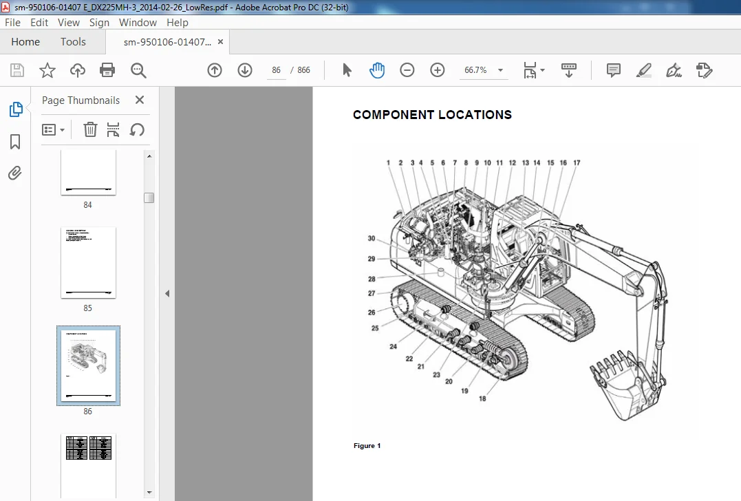
sm-950106-01407 E_DX225MH-3_2014-02-26...............................................................  7
	Safety...........................................................................................  9
		Material Handler Maintenance Safety SP002322NA............................................... 11
			Safety Instructions...................................................................... 15
			Applicable Models........................................................................ 15
			Safety Messages.......................................................................... 16
				Signal Words......................................................................... 16
			Safety Decals............................................................................ 17
			General.................................................................................. 17
				Safe Operation is Operator's Responsibility.......................................... 17
				Know Your Machine.................................................................... 17
				Proper Work Tools and Attachments.................................................... 18
				Pressurized Fluids................................................................... 18
				Flying or Falling Objects............................................................ 19
				Personal Protective Equipment (PPE).................................................. 20
				Correction of Machine Problems....................................................... 20
				Crushing and Cutting................................................................. 20
				Hot Coolant and Oils - Burn Prevention............................................... 21
				Fire and Explosion Prevention........................................................ 22
				Fire Extinguisher and First-Aid Kit (Emergency Medical Kit).......................... 25
				Electrical System and Electrical Shock............................................... 26
			Transportation........................................................................... 30
				Obey State and Local Over-the-Road Regulations....................................... 30
				Loading and Unloading................................................................ 30
				Transporting Machine................................................................. 31
			Operation................................................................................ 32
				Before Engine Starting............................................................... 32
				Work Site............................................................................ 33
				Mounting/Dismounting................................................................. 34
				Cleaning............................................................................. 36
				Operator Station..................................................................... 36
				Seat Belt............................................................................ 37
				Visibility Information............................................................... 38
				Boost Starting or Charging Engine Batteries.......................................... 39
				Swinging or Traveling................................................................ 41
				Lifting.............................................................................. 43
				Towing............................................................................... 44
				Attachment........................................................................... 45
				Equipment Lowering with Engine Stopped............................................... 45
				Lowering Elevating Cab with Engine Stopped........................................... 46
				Engine Stop.......................................................................... 46
				Parking Machine...................................................................... 47
				Preservation/Storing Machine......................................................... 48
			Maintenance.............................................................................. 50
				Cleaning............................................................................. 54
				Proper Tools and Clothing............................................................ 54
				Disassembling Precautions............................................................ 54
				Use of Lighting...................................................................... 55
				Fire and Explosion Prevention........................................................ 55
				Burn Prevention...................................................................... 56
				Rubber That Contains Fluorides....................................................... 57
				Rubber and Plastics.................................................................. 58
				Welding Repairs...................................................................... 59
				Warning for Counterweight and Front Attachment Removal............................... 60
				Lock Inspection Covers............................................................... 61
				Working on Machine................................................................... 61
				Accumulator.......................................................................... 62
				Compressed Air....................................................................... 62
				Track Tension Adjustments............................................................ 63
				Supports and Blocking for Work Equipment............................................. 63
				High-pressure Lines, Tubes and Hoses................................................. 64
				Battery.............................................................................. 65
			Environment and Circumstances............................................................ 67
				Work Site Areas Requiring Extra Caution.............................................. 67
				High-voltage Cables.................................................................. 68
				Working in Water..................................................................... 69
				Working in Contaminated Environment.................................................. 69
				Operation in Extreme Conditions...................................................... 70
				Exhaust Ventilation.................................................................. 74
				Asbestos Information................................................................. 74
				Silica Dust Information.............................................................. 75
				Disposal of Hazardous Materials...................................................... 75
	Specifications................................................................................... 77
		Specifications SP002491NA.................................................................... 79
			Safety Instructions...................................................................... 83
			Applicable Models........................................................................ 83
			General Description...................................................................... 85
			Component Locations...................................................................... 86
				Tilting Riser........................................................................ 88
				Elevating Cab........................................................................ 89
			General Dimensions....................................................................... 90
				Tilting Riser With One - Piece Boom.................................................. 90
				Elevating Cab With One - Piece Boom.................................................. 91
			Working Range............................................................................ 92
				One - Piece Boom..................................................................... 92
			General Specifications................................................................... 93
			Performance Tests........................................................................ 96
			Material Handler Performance Measurements................................................ 97
				Test Conditions...................................................................... 97
				Travel Speed and Travel Motor Balance (Steering Deviation) Tests..................... 97
				Swing Speed and Deceleration Force Test.............................................. 99
				Cylinder Performance Tests...........................................................101
	General Maintenance..............................................................................103
		General Maintenance Instructions SP002454NA..................................................105
			Safety Instructions......................................................................109
			Applicable Models........................................................................109
			Welding Precautions and Instructions.....................................................110
			Hydraulic System - General Precautions...................................................111
			Maintenance Service and Repair Procedure.................................................113
				General Precautions..................................................................113
			Hydraulic System Cleanliness and Oil Leaks...............................................114
				Maintenance Precautions for Hydraulic System Service.................................114
				Oil Leakage Precautions..............................................................115
			Cleaning and Inspection..................................................................116
				General Instructions.................................................................116
				Bearing Inspection...................................................................117
		Standard Torques.............................................................................125
			Safety Instructions......................................................................129
			Applicable Models........................................................................129
			Torque Values for Standard Metric Fasteners..............................................130
			Torque Values for Standard U.S. Fasteners................................................131
			Type 8 Phosphate Coated Hardware.........................................................133
			Torque Values for Hose Clamps............................................................134
			ORFS Swivel Nut Recommended Torque.......................................................134
			Torque Values for Split Flanges..........................................................135
			Torque Wrench Extension Tools............................................................136
				Torque Multiplication................................................................136
				Other Uses for Torque Wrench Extension Tools.........................................137
				Tightening Torque Specifications (Metric)............................................138
	Upper Structure..................................................................................141
		Cabin SP002324NA.............................................................................143
			Safety Instructions......................................................................147
			Applicable Models........................................................................147
			Cabin Identification.....................................................................148
				General Instructions for Cabin.......................................................148
		Counterweight SP002492NA.....................................................................157
			Safety Instructions......................................................................161
			Applicable Models........................................................................161
			General..................................................................................162
				Warning for Counterweight and Front Attachment Removal...............................162
			Installation.............................................................................166
		Fuel Tank SP002493NA.........................................................................169
			Safety Instructions......................................................................173
			Applicable Models........................................................................173
			General Description......................................................................  0
				Specifications.......................................................................175
			Start-up Procedures......................................................................183
		Fuel Transfer Pump (Option) SP002534NA.......................................................185
			Safety Instructions......................................................................189
			Applicable Models........................................................................189
			Troubleshooting..........................................................................192
			Replacement of Rotor and Vane............................................................192
		Swing Bearing SP002329NA.....................................................................195
			Safety Instructions......................................................................199
			Applicable Models........................................................................199
			Swing Bearing Maintenance................................................................200
				Operating Recommendation.............................................................200
				Measuring Swing Bearing Axial Play...................................................200
				Measuring Bearing Lateral Play.......................................................200
				Swing Bearing Basic Operation........................................................201
				Disassembly..........................................................................201
				Assembly.............................................................................203
	Lower Structure and Chassis......................................................................205
		Track Assembly SP002494NA....................................................................207
			Safety Instructions......................................................................211
			Applicable Models........................................................................211
			General Description......................................................................212
			Track Tension............................................................................213
			Cleaning and Inspection (Wear Limits and Tolerances).....................................215
				Track Shoe...........................................................................216
				Lower Roller.........................................................................218
				Upper Roller.........................................................................219
				Front Idler..........................................................................220
			Track Shoes and Links....................................................................221
				Track Removal........................................................................221
				Track Installation...................................................................222
			Front Idler Roller.......................................................................223
				Parts List...........................................................................223
				Front Idler Roller Disassembly.......................................................224
				Front Idler Roller Reassembly........................................................226
			Lower Roller.............................................................................228
				Parts List...........................................................................228
				Lower Roller Removal.................................................................229
				Lower Roller Disassembly.............................................................229
				Lower Roller Reassembly..............................................................230
				Lower Roller Installation............................................................231
			Upper Roller.............................................................................232
				Parts List...........................................................................232
				Upper Roller Removal.................................................................233
				Upper Roller Disassembly.............................................................233
				Upper Roller Reassembly..............................................................235
			Track Spring and Track Adjusting Cylinder................................................236
				Parts List...........................................................................236
	Engine and Drivetrain............................................................................239
		Engine Coolant Heater (Option) SP002328NA....................................................241
			Safety Instructions......................................................................245
			Applicable Models........................................................................245
			Disassembly and Assembly.................................................................246
				Changing the Circulating Pump........................................................246
				Changing the Temperature Limiter.....................................................248
				Changing the Temperature Sensor......................................................249
				Changing the Combustion Air Fan......................................................251
				Changing the Burner, Flame Monitor and Glow Plug.....................................253
				Changing the Burner Head.............................................................255
				Changing the Heat Exchanger..........................................................257
		Drive Coupling (Main Pump)...................................................................259
			Safety Instructions......................................................................263
			Applicable Models........................................................................263
			Drive Coupling...........................................................................264
			Special Tools............................................................................265
			Installation of Drive Coupling...........................................................266
				Installation Procedure...............................................................268
	Hydraulics.......................................................................................269
		Hydraulic System Troubleshooting, Testing and Adjustment SP002535NA..........................271
			Safety Instructions......................................................................275
			Applicable Models........................................................................275
			Hydraulic System - General Notes.........................................................276
			Hydraulic Schematic......................................................................277
				General Notes........................................................................277
			Operation of Working Components..........................................................279
				Boom Operating Circuit...............................................................279
				Boom Up Circuit......................................................................279
				Boom Down Circuit....................................................................279
				Arm Operating Circuit................................................................280
				Arm Crowd Circuit....................................................................280
				Arm Dump Circuit.....................................................................280
				Grapple Operating Circuit............................................................281
				Grapple Close Circuit................................................................281
				Grapple Open Circuit.................................................................281
				Swing Operating Circuit..............................................................281
				Right Swing Operating Circuit........................................................282
				Left Swing Operating Circuit.........................................................282
				Swing Relief Valve and Makeup Valve..................................................282
				Travel Operating Circuit.............................................................282
				Forward Travel Circuit...............................................................283
				Reverse Travel Circuit...............................................................283
			Procedural Troubleshooting Baseline Recommendations......................................284
				Initial Checks and Tests to Establish Operating Condition of the Material Handler....284
			Pilot Pressure...........................................................................286
				Adjustment and Testing...............................................................286
			Power Mode Valve.........................................................................287
				Current Signal and Hydraulic Pressure Adjustments....................................287
			Pressure Up Valve........................................................................288
				Checks and Adjustments...............................................................288
			Pump Input Power Control.................................................................290
				Pump Regulator Adjustment............................................................290
			Flow Meter and Flow Meter Kit Installation and Testing...................................293
			Swing System Troubleshooting.............................................................295
				Precautions/Initial Checks...........................................................295
				Swing Relief Valve Checking and Adjustment...........................................296
			Troubleshooting - Swing Gearbox..........................................................298
			Troubleshooting - Hydraulic Problems.....................................................299
			Troubleshooting - Control Valve..........................................................301
			Troubleshooting - Travel Control Valve...................................................302
			Troubleshooting - Joystick Control Valve.................................................303
		Accumulator SP002455NA.......................................................................305
			Safety Instructions......................................................................309
			Applicable Models........................................................................309
			General Description......................................................................  0
				Specifications.......................................................................312
		Center Joint (Swivel) SP002456NA.............................................................313
			Safety Instructions......................................................................317
			Applicable Models........................................................................317
			General Description......................................................................319
				Parts List...........................................................................320
			Troubleshooting, Testing and Adjustment..................................................321
				Inspection...........................................................................321
				Testing..............................................................................321
			Disassembly..............................................................................322
			Reassembly...............................................................................325
		Cylinders SP002497NA.........................................................................327
			Safety Instructions......................................................................331
			Applicable Models........................................................................331
			General Description......................................................................332
				Theory of Operation..................................................................332
				Parts List...........................................................................334
			Disassembly..............................................................................357
			Reassembly...............................................................................362
		Swing Device SP002498NA......................................................................367
			Safety Instructions......................................................................371
			Applicable Models........................................................................371
			Indication of Type.......................................................................372
			Specifications...........................................................................373
			Structure and Principle of Operation.....................................................374
				Structure............................................................................374
				Principles of Operation..............................................................379
				Valve Casing.........................................................................380
				Brake Part...........................................................................383
			Cautions for Operation...................................................................384
				Inspection...........................................................................384
				Direction of Rotation................................................................384
				External Load at the End of Shaft....................................................385
				Hydraulic Oil and Temperature Range..................................................385
				Filter...............................................................................386
				Installation and Piping..............................................................386
				Oil Filling and Air Breather.........................................................387
				Instructions before Starting to Operate..............................................387
			Troubleshooting..........................................................................388
				General Pre-caustions................................................................388
				Examination of Hydraulic Motor.......................................................388
				Troubleshooting......................................................................389
			Disassembly and Reassembly...............................................................392
				Disassemble Swing Motor..............................................................394
				Reassemble Swing Motor...............................................................398
				Disassemble the Reduction Gear.......................................................403
				Reassemble the Reduction Gear........................................................407
				Maintenance Instructions.............................................................415
		Travel Device................................................................................417
			Safety Instructions......................................................................421
			Applicable Models........................................................................421
			TM40VD Operation Manual..................................................................422
			Specifications...........................................................................422
			Indication of Type.......................................................................423
				Basic Structure and Diagram..........................................................424
					Basic Structure of TM Motor......................................................424
				Operation Principles.................................................................425
					Reducer..........................................................................425
					Hydraulic Motor (Brake Valve, Parking Brake, High and Low 2-Speed Shifting)......426
				Cautions for Operation...............................................................432
					Installation Method (Refer to the External Specifications Diagrams.).............432
					Piping...........................................................................432
					Hydraulic Oil....................................................................433
					Lubricating Oil..................................................................434
					Maintenance......................................................................435
					Troubleshooting..................................................................436
				External Specifications Diagrams.....................................................438
				Basic Structure and Diagrams.........................................................439
					Assembly Cross-Section...........................................................439
			TM40VD Maintenance Instructions..........................................................442
				Precautions..........................................................................442
				Tools List for Disassembly and Reassembly............................................443
					Standard Tools...................................................................443
					Machined Tools...................................................................444
				Disassembly Instructions.............................................................446
					General Cautions.................................................................446
					Disassembly procedure............................................................446
				Reassembly...........................................................................457
					General Precautions..............................................................457
					Reassembly Procedure.............................................................457
					Checking Facts After Assembly....................................................471
				Testing..............................................................................472
				List of Seals........................................................................474
		Main Pump....................................................................................475
			Safety Instructions......................................................................479
			Applicable Models........................................................................479
			Pump Maintenance.........................................................................  0
				Parts List...........................................................................482
				Tools................................................................................484
				Tightening Torque....................................................................485
			Disassembly..............................................................................486
			Reassembly...............................................................................489
			Pump Body Maintenance Standards..........................................................492
				Change Standards of Worn Parts.......................................................492
				Fix Standards of Cylinder Block, Valve Plate, and Swash Plate (Shoe Plate)...........493
		PTO Server...................................................................................495
			Safety Instructions......................................................................499
			Applicable Models........................................................................499
			Pump Maintenance.........................................................................500
			Disassembly..............................................................................501
			Reassembly...............................................................................503
			Maintenance Standards of Pump Body.......................................................504
		Gear Pump....................................................................................507
			Safety Instructions......................................................................511
			Applicable Models........................................................................511
			Single Gear Pump.........................................................................512
				Disassembly..........................................................................512
				Reassembly...........................................................................514
		Main Control Valve SP002403NA................................................................519
			Safety Instructions......................................................................523
			Applicable Models........................................................................523
			General Description......................................................................524
				Theory of Operation..................................................................524
				Parts List...........................................................................556
				Specifications.......................................................................561
			Troubleshooting, Testing and Adjustment..................................................562
				Troubleshooting......................................................................562
				Adjustment of Valves.................................................................563
			Removal..................................................................................565
			Disassembly..............................................................................566
			Cleaning and Inspection (Wear Limits and Tolerances).....................................575
				Cleaning.............................................................................575
				Inspection...........................................................................575
			Reassembly...............................................................................576
				Caution on Assembly..................................................................576
				Sequence of Subassembly..............................................................577
				Maintenance of Relief Valves.........................................................583
			Installation.............................................................................586
			Start-up Procedures......................................................................587
		Remote Control Valve (Work Lever / Joystick) SP002395NA......................................589
			Safety Instructions......................................................................593
			Applicable Models........................................................................593
			General Description......................................................................595
				Theory of Operation..................................................................595
				Parts List...........................................................................596
				Specifications.......................................................................598
				Torques..............................................................................598
			Tools and Materials......................................................................598
			Disassembly..............................................................................599
			Reassembly...............................................................................602
			Start-up Procedures......................................................................610
		Travel Control Valve (with Damper) SP002381NA................................................611
			Safety Instructions......................................................................615
			Applicable Models........................................................................615
			General Description......................................................................616
				Theory of Operation..................................................................616
				Pressure Reducing Valve..............................................................617
				Operating Theory of Damper Mechanism.................................................618
			Causes of Faults and Measures............................................................619
				Parts List...........................................................................620
				Specification........................................................................622
				Torques..............................................................................622
			Disassembly..............................................................................626
			Cleaning and Inspection (Wear Limits and Tolerances).....................................628
			Reassembly...............................................................................629
			Installation.............................................................................634
			Start-up Procedures......................................................................637
		Solenoid Valve Assembly SP002406NA...........................................................639
			Safety Instructions......................................................................643
			Applicable Models........................................................................643
			5-Solenoid Valve.........................................................................644
				Parts List...........................................................................644
				Functions of 5-Solenoid Valve Assembly...............................................645
				Assembly Diagram and Tools Required..................................................646
				Cautions During Disassembly and Reassembly...........................................647
				Solenoid Valve Diagram...............................................................648
				Check Points and Solutions for Problems..............................................649
		Hydraulic Schematic SP002507NA...............................................................651
			Safety Instructions......................................................................655
			Applicable Models........................................................................655
			DX225LC-3/DX225MH-3......................................................................657
	Electrical System................................................................................659
		Electrical System SP002337NA.................................................................661
			Safety Instructions......................................................................667
			Applicable Models........................................................................667
			Introduction.............................................................................668
			Electrical Supply System.................................................................670
			Engine Starting Circuit..................................................................672
				Start Operation......................................................................672
				After Start..........................................................................674
			Engine Preheating System.................................................................676
			Engine Stop..............................................................................678
			Monitoring System........................................................................681
				Instrument Panel.....................................................................682
				Functional Check.....................................................................682
				Monitoring System Schematic..........................................................684
			Operation................................................................................686
				Instruments..........................................................................686
			Warning and Indicator Lights.............................................................  0
				Indication of Multifunction Gauge....................................................690
			Initial Operation........................................................................691
			Graphic Information Area Display.........................................................692
				Overview.............................................................................692
				Main Menus for the Graphic Display Area..............................................692
				Menu Selector Buttons................................................................692
			Special Menu.............................................................................725
				Entering/Accessing and Exiting/Escaping Menus........................................725
				Special Menu Selections..............................................................726
			Electronic Hydraulic Control System (e-EPOS).............................................752
				Control System Schematic.............................................................752
			Power Plus Mode Control..................................................................754
				Operation............................................................................756
			Power Mode Control - Circuit Diagram.....................................................758
			Engine Control System....................................................................760
			Engine Control Dial......................................................................761
			Engine Control Circuit Diagram...........................................................762
			Automatic Deceleration Control (Auto Idle Control).......................................764
			Engine Overheat Protection System........................................................766
			Power Boost Mode.........................................................................768
				Operation............................................................................768
				Power Boost Control - Circuit Diagram................................................770
			Automatic Travel Speed Control...........................................................772
			Self-diagnostic Function.................................................................775
				e-EPOS Controller....................................................................775
			Air Conditioner System...................................................................777
				Outline..............................................................................777
				Internal and External Filters........................................................778
				Air-Conditioning System Layout.......................................................780
				Air Conditioner/heater Circuit Diagram...............................................781
				Air Conditioner/heater Unit..........................................................782
				Ambient Air Temperature Sensor.......................................................787
				Compressor...........................................................................796
				Receiver Dryer.......................................................................796
			Troubleshooting..........................................................................797
			Weight of R134a Gas Used In Machines.....................................................799
			Refrigerant System Repairs...............................................................800
				Refrigerant Safe Handling Procedures.................................................800
				Repair and Replacement Procedure.....................................................801
				Refrigerant Recovery.................................................................803
				Vacuuming Refrigerant System.........................................................803
				Leakage Check........................................................................805
				Refrigerant Charging.................................................................805
				Inspecting System For Leakage........................................................807
			Wiper System.............................................................................808
				Wiper Circuit........................................................................808
				Wiper operation......................................................................809
			Lighting System..........................................................................  0
				Kind of Light........................................................................813
				Operation............................................................................813
			Overload Warning Device..................................................................814
				Overload Warning Device Circuit Diagram..............................................814
		Electrical Schematic SP002508NA..............................................................817
			Safety Instructions......................................................................821
			Applicable Models........................................................................821
			DX140LC-3/DX180LC-3/DX225LC-3/DX225MH-3/DX255LC-3........................................823
	Attachments......................................................................................825
		Boom and Arm SP002505NA......................................................................827
			Safety Instructions......................................................................831
			Applicable Models........................................................................831
			Front Attachment Pin Specifications......................................................832
				DX225MH-3............................................................................833
			Front Attachment - Removal and Installation..............................................834
				Arm Removal Procedure................................................................834
				Boom Removal Procedure...............................................................841
			Installation.............................................................................847
				Boom Installation Procedure..........................................................847
				Arm Installation Procedure...........................................................854
			Start-up Procedures......................................................................859
		Attachment SP002506NA........................................................................861
			Safety Instructions......................................................................865
			Applicable Models........................................................................865
			Attachments..............................................................................866
				Installation and Removal.............................................................866
DOOSAN DX225MH 3 EXCAVATOR SHOP MANUAL 950106-01407E – PDF DOWNLOAD:
IMAGES PREVIEW OF THE MANUAL:
PLEASE NOTE:
- This is the same manual used by the DEALERSHIPS to SERVICE your vehicle.
- The manual can be all yours – Once payment is complete, you will be taken to the download page from where you can download the manual. All in 2-5 minutes time!!
- Need any other service / repair / parts manual, please feel free to contact us at heydownloadss @gmail.com . We may surprise you with a nice offer
S.M