Doosan DX380LC-3 (OCEANNAI) Excavator Shop Manual 950106-03151OC – PDF DOWNLOAD
Original price was: $65.95.$31.95Current price is: $31.95.
Doosan DX380LC-3 (OCEANNAI) Excavator Shop Manual 950106-03151OC – PDF DOWNLOAD
Description
Doosan DX380LC-3 (OCEANNAI) Excavator Shop Manual 950106-03151OC – PDF DOWNLOAD
FILE DETAILS:
Doosan DX380LC-3 (OCEANNAI) Excavator Shop Manual 950106-03151OC – PDF DOWNLOAD
Format: PDF
Language: English
Brand: Doosan
DESCRIPTION:
Doosan DX380LC-3 (OCEANNAI) Excavator Shop Manual 950106-03151OC – PDF DOWNLOAD
Know Your Machine :
- Know how to operate your machine. Know the purpose of all controls, gauges, signals, indicators and monitor displays. Know the rated load capacity, speed range, braking and steering characteristics, turning radius and operating clearances.
- Keep in mind that rain, snow, ice, loose gravel, soft ground, slopes etc., can change operating capabilities of your machine. Proper Work
Doosan DX380LC-3 (OCEANNAI) Excavator Shop Manual 950106-03151OC – PDF DOWNLOAD
DX380LC-3…………………………………………………………………………. 0
Table of Contents………………………………………………………………. 6
Safety………………………………………………………………………… 8
Track Excavator Maintenance Safety SP003114……………………………………. 10
Safety Instructions……………………………………………………… 14
Applicable Models……………………………………………………….. 14
Safety Messages…………………………………………………………. 15
Signal Words………………………………………………………… 15
Other Signal Words…………………………………………………… 16
Safety Decals…………………………………………………………… 16
General………………………………………………………………… 17
Safe Operation is Operator’s Responsibility…………………………….. 17
Know Your Machine……………………………………………………. 17
Proper Work Tools and Attachments……………………………………… 17
Pressurized Fluids…………………………………………………… 18
Flying or Falling Objects…………………………………………….. 19
Personal Protective Equipment (PPE)……………………………………. 19
Correction of Machine Problems………………………………………… 19
Crushing and Cutting…………………………………………………. 20
Hot Coolant and Oils – Burn Prevention…………………………………. 21
Fire and Explosion Prevention…………………………………………. 21
Fire Extinguisher and First-Aid Kit (Emergency Medical Kit)………………. 25
Electrical System and Electrical Shock…………………………………. 25
Rollover Protective Structure (ROPS)…………………………………… 26
Transportation………………………………………………………….. 29
Obey State and Local Over-the-Road Regulations………………………….. 29
Loading and Unloading………………………………………………… 29
Transporting Machine…………………………………………………. 30
Operation………………………………………………………………. 31
Before Engine Starting……………………………………………….. 31
Work Site…………………………………………………………… 32
Mounting/Dismounting…………………………………………………. 33
Cleaning……………………………………………………………. 34
Operator Station…………………………………………………….. 34
Seat Belt…………………………………………………………… 35
Visibility Information……………………………………………….. 36
Boost Starting or Charging Engine Batteries…………………………….. 37
Swinging or Traveling………………………………………………… 39
Lifting and Digging………………………………………………….. 41
Operation on Slopes………………………………………………….. 42
Towing……………………………………………………………… 43
Attachment………………………………………………………….. 44
Equipment Lowering with Engine Stopped…………………………………. 44
Engine Stop…………………………………………………………. 44
Parking Machine……………………………………………………… 45
Preservation/Storing Machine………………………………………….. 46
Maintenance…………………………………………………………….. 48
Cleaning……………………………………………………………. 52
Proper Tools and Clothing…………………………………………….. 52
Disassembling Precautions…………………………………………….. 52
Use of Lighting……………………………………………………… 53
Fire and Explosion Prevention…………………………………………. 53
Burn Prevention……………………………………………………… 54
Rubber That Contains Fluorides………………………………………… 55
Rubber and Plastics………………………………………………….. 56
Welding Repairs……………………………………………………… 57
Warning for Counterweight and Front Attachment Removal…………………… 58
Lock Inspection Covers……………………………………………….. 59
Working on Machine…………………………………………………… 59
Accumulator…………………………………………………………. 60
Compressed Air………………………………………………………. 60
Track Tension Adjustments…………………………………………….. 61
Supports and Blocking for Work Equipment……………………………….. 61
High-pressure Lines, Tubes and Hoses…………………………………… 62
Battery…………………………………………………………….. 63
Environment and Circumstances…………………………………………….. 65
Work Site Areas Requiring Extra Caution………………………………… 65
High-voltage Cables………………………………………………….. 67
Underground Operation………………………………………………… 68
Working in Water…………………………………………………….. 68
Working in Contaminated Environment……………………………………. 68
Operation in Extreme Conditions……………………………………….. 69
Exhaust Ventilation………………………………………………….. 73
Asbestos Information…………………………………………………. 74
Silica Dust Information………………………………………………. 74
Disposal of Hazardous Materials……………………………………….. 75
Sound………………………………………………………………. 76
Vibration…………………………………………………………… 76
Specifications…………………………………………………………………. 78
Specification for DX380LC-3 SP003115………………………………………….. 80
Safety Instructions……………………………………………………… 84
Applicable Models……………………………………………………….. 84
General Description……………………………………………………… 86
Component Locations……………………………………………………… 87
General Dimensions………………………………………………………. 89
Working Range…………………………………………………………… 91
General Specifications…………………………………………………… 93
Approximate Weight of Workload Materials…………………………………… 97
Performance Tests……………………………………………………….. 99
Excavator Performance Measurements…………………………………………100
Test Conditions………………………………………………………100
Travel Speed and Travel Motor Balance (Steering Deviation) Tests…………..101
Swing Speed and Deceleration Force Test…………………………………102
Cylinder Performance Tests…………………………………………….104
General Maintenance……………………………………………………………..106
General Maintenance Instructions SP002454………………………………………108
Safety Instructions………………………………………………………112
Applicable Models………………………………………………………..112
Welding Precautions and Instructions……………………………………….113
Hydraulic System – General Precautions……………………………………..114
Maintenance Service and Repair Procedure……………………………………116
General Precautions…………………………………………………..116
Hydraulic System Cleanliness and Oil Leaks………………………………….117
Maintenance Precautions for Hydraulic System Service……………………..117
Oil Leakage Precautions……………………………………………….118
Cleaning and Inspection…………………………………………………..119
General Instructions………………………………………………….119
Bearing Inspection……………………………………………………120
Standard Torques…………………………………………………………….128
Safety Instructions………………………………………………………132
Applicable Models………………………………………………………..132
Torque Values for Standard Metric Fasteners…………………………………133
Torque Values for Standard U.S. Fasteners…………………………………..134
Type 8 Phosphate Coated Hardware…………………………………………..136
Torque Values for Hose Clamps……………………………………………..137
ORFS Swivel Nut Recommended Torque…………………………………………137
Torque Values for Split Flanges……………………………………………138
Torque Wrench Extension Tools……………………………………………..139
Torque Multiplication…………………………………………………139
Other Uses for Torque Wrench Extension Tools…………………………….140
Tightening Torque Specifications (Metric)……………………………….141
Upper Structure…………………………………………………………………144
Cabin SP003124………………………………………………………………146
Safety Instructions………………………………………………………150
Applicable Models………………………………………………………..150
Cabin Identification……………………………………………………..151
Rollover Protective Structure (ROPS)……………………………………151
Counterweight SP002606……………………………………………………….160
Safety Instructions………………………………………………………164
Applicable Models………………………………………………………..164
General…………………………………………………………………165
Warning for Counterweight and Front Attachment Removal……………………165
Installation…………………………………………………………….168
Fuel Tank SP002410…………………………………………………………..170
Safety Instructions………………………………………………………174
Applicable Models………………………………………………………..174
General Description……………………………………………………… 0
Specifications……………………………………………………….176
Start-up Procedures………………………………………………………184
Fuel Transfer Pump (Option) SP003116…………………………………………..186
Safety Instructions………………………………………………………190
Applicable Models………………………………………………………..190
Troubleshooting………………………………………………………….193
Replacement of Rotor and Vane……………………………………………..193
Swing Bearing SP002329……………………………………………………….196
Safety Instructions………………………………………………………200
Applicable Models………………………………………………………..200
Swing Bearing Maintenance…………………………………………………201
Operating Recommendation………………………………………………201
Measuring Swing Bearing Axial Play……………………………………..201
Measuring Bearing Lateral Play…………………………………………201
Swing Bearing Basic Operation………………………………………….202
Disassembly………………………………………………………….202
Assembly…………………………………………………………….204
Lower Structure and Chassis………………………………………………………206
Track Assembly SP003117………………………………………………………208
Safety Instructions………………………………………………………212
Applicable Models………………………………………………………..212
General Description………………………………………………………213
Track Tension……………………………………………………………214
Cleaning and Inspection (Wear Limits and Tolerances)…………………………216
Track Shoe…………………………………………………………..217
Lower Roller…………………………………………………………219
Upper Roller…………………………………………………………220
Front Idler………………………………………………………….221
Track Shoes and Links…………………………………………………….222
Track Removal………………………………………………………..222
Track Installation……………………………………………………223
Front Idler……………………………………………………………..225
Parts List…………………………………………………………..225
Front Idler Disassembly……………………………………………….226
Front Idler Reassembly………………………………………………..228
Lower Roller…………………………………………………………….229
Parts List…………………………………………………………..229
Lower Roller Removal………………………………………………….230
Lower Roller Disassembly………………………………………………230
Lower Roller Reassembly……………………………………………….231
Lower Roller Installation……………………………………………..232
Upper Roller…………………………………………………………….233
Parts List…………………………………………………………..233
Upper Roller Removal………………………………………………….234
Upper Roller Disassembly………………………………………………234
Upper Roller Reassembly……………………………………………….236
Track Spring and Track Adjusting Cylinder…………………………………..237
Parts List…………………………………………………………..237
Engine and Drivetrain……………………………………………………………240
Drive Coupling (Main Pump) SP003118……………………………………………242
Safety Instructions………………………………………………………246
Applicable Models………………………………………………………..246
Drive Coupling…………………………………………………………..247
Hydraulics……………………………………………………………………..250
Hydraulic System Troubleshooting, Testing and Adjustment SP003119…………………252
Safety Instructions………………………………………………………256
Applicable Models………………………………………………………..256
Hydraulic System – General Notes…………………………………………..257
Hydraulic Schematic………………………………………………………257
General Notes………………………………………………………..257
Operation of Working Components……………………………………………259
Boom Operating Circuit………………………………………………..259
Boom Up Circuit………………………………………………………259
Boom Down Circuit…………………………………………………….259
Arm Operating Circuit…………………………………………………260
Arm Crowd Circuit…………………………………………………….260
Arm Dump Circuit……………………………………………………..260
Bucket Operating Circuit………………………………………………261
Bucket Crowd Circuit………………………………………………….261
Bucket Dump Circuit…………………………………………………..261
Swing Operating Circuit……………………………………………….261
Right Swing Operating Circuit………………………………………….262
Left Swing Operating Circuit…………………………………………..262
Swing Relief Valve and Makeup Valve…………………………………….262
Travel Operating Circuit………………………………………………262
Forward Travel Circuit………………………………………………..263
Reverse Travel Circuit………………………………………………..263
Procedural Troubleshooting Baseline Recommendations………………………….264
Initial Checks and Tests to Establish Operating Condition of the Excavator….264
Pilot Pressure…………………………………………………………..265
Adjustment and Testing………………………………………………..265
Pump Swash Plate…………………………………………………………266
Adjustment and Testing………………………………………………..266
Pump EPPRV………………………………………………………………267
Adjustment and Testing………………………………………………..267
Pump Pressure……………………………………………………………268
Adjustment and Testing………………………………………………..268
Pump Regulator…………………………………………………………..269
Adjustment and Testing………………………………………………..269
Installation and Testing of Flow Meter and Flow Meter Kit…………………….271
Installation and Testing Procedures…………………………………….271
Swing System Troubleshooting………………………………………………272
Precautions/Initial Checks…………………………………………….272
Swing Relief Valve Checking and Adjustment………………………………273
Troubleshooting – Swing Gearbox……………………………………………275
Troubleshooting – Hydraulic Problems……………………………………….276
Troubleshooting – Main Pump……………………………………………….279
Troubleshooting – Control Valve……………………………………………281
Troubleshooting – Travel Control Valve……………………………………..283
Troubleshooting – Joystick Control Valve……………………………………284
Accumulator SP002455…………………………………………………………286
Safety Instructions………………………………………………………290
Applicable Models………………………………………………………..290
General Description……………………………………………………… 0
Specifications……………………………………………………….293
Center Joint (Swivel) SP002545………………………………………………..294
Safety Instructions………………………………………………………298
Applicable Models………………………………………………………..298
General Description………………………………………………………299
Parts List…………………………………………………………..299
Troubleshooting, Testing and Adjustment…………………………………….301
Inspection…………………………………………………………..301
Testing……………………………………………………………..301
Disassembly……………………………………………………………..302
Reassembly………………………………………………………………305
Cylinders SP002422…………………………………………………………..308
Safety Instructions………………………………………………………312
Applicable Models………………………………………………………..312
General Description………………………………………………………313
Theory of Operation…………………………………………………..313
Parts List…………………………………………………………..315
Disassembly……………………………………………………………..338
Reassembly………………………………………………………………343
Swing Device SP002413………………………………………………………..348
Safety Instructions………………………………………………………352
Applicable Models………………………………………………………..352
Structure and Principle of Operation……………………………………353
Cautions for Operation………………………………………………..363
Troubleshooting………………………………………………………367
Disassembly and Reassembly…………………………………………….371
Remove and Install Swing Device……………………………………………373
Removal……………………………………………………………..373
Installation…………………………………………………………376
Maintenance Guidelines………………………………………………..399
Travel Device SP002609……………………………………………………….400
Safety Instructions………………………………………………………404
Applicable Models………………………………………………………..404
Basic Structure and Drawings…………………………………………..406
Operation Principle…………………………………………………..411
Operation Instructions………………………………………………..420
Troubleshooting………………………………………………………423
Maintenance Instructions………………………………………………425
Remove and Install Travel Device…………………………………………..428
Removal……………………………………………………………..428
Disassembly………………………………………………………….429
Assembly…………………………………………………………….439
Installation…………………………………………………………456
Matters to Check After Assembly………………………………………..457
Performance Test……………………………………………………..457
Main Pump SP002415…………………………………………………………..460
Safety Instructions………………………………………………………464
Applicable Models………………………………………………………..464
Product description………………………………………………………466
Performance Description……………………………………………….466
Device Description……………………………………………………466
Manual Override………………………………………………………469
Parts List…………………………………………………………..471
Transport and storage…………………………………………………….473
Transporting the Axial Piston Unit……………………………………..473
Storing the Axial Piston Unit………………………………………….475
Installation…………………………………………………………….478
Unpacking……………………………………………………………478
Installation Conditions……………………………………………….479
Installation Position…………………………………………………481
Installing the Axial Piston Unit……………………………………….483
Commissioning……………………………………………………………495
Initial Commissioning…………………………………………………496
Recommissioning After Standstill……………………………………….501
Running-in Phase……………………………………………………..501
Maintenance and repair……………………………………………………502
Cleaning and Care…………………………………………………….502
Inspection…………………………………………………………..503
Maintenance………………………………………………………….503
Repair………………………………………………………………504
Spare Parts………………………………………………………….504
Decommissioning………………………………………………………….505
Removal and replacement…………………………………………………..505
Required Tools……………………………………………………….505
Preparing for Removal…………………………………………………505
Removing the Axial Piston Unit…………………………………………506
Preparing the Components for Storage or Further Use………………………506
Troubleshooting………………………………………………………….507
How to Proceed for Troubleshooting……………………………………..507
Malfunction Table…………………………………………………….508
Replacing seals and assembly groups………………………………………..510
Sealing the Port Plate with Valve………………………………………518
Sealing or Replacing the Pressure Reducing Valve…………………………520
Replacing the Angle Position Sensor…………………………………….522
Replacing Sealing Nuts………………………………………………..524
Tightening torques……………………………………………………….525
Slotted Screws……………………………………………………….525
Threaded Plugs……………………………………………………….526
Sealing Nuts…………………………………………………………527
Gear Pump SP002568…………………………………………………………..528
Safety Instructions………………………………………………………532
Applicable Models………………………………………………………..532
Disassembling Single Gear Pump (Opt)……………………………………….533
Reassembling Single Gear Pump (Opt)………………………………………..536
Fan Motor for Oil Cooler SP003127……………………………………………..540
Safety Instructions………………………………………………………544
Applicable Models………………………………………………………..544
Disassembly……………………………………………………………..546
Assembly………………………………………………………………..549
Preassemble………………………………………………………….549
Assembling…………………………………………………………..550
Fan Pump SP002553……………………………………………………………552
Safety Instructions………………………………………………………556
Applicable Models………………………………………………………..556
View……………………………………………………………………558
ED – Valve…………………………………………………………..558
General Repair Guidelines…………………………………………………559
Sealing Control Valve…………………………………………………….562
Disassembly……………………………………………………………..563
Overview…………………………………………………………….563
Remove Rotary Group…………………………………………………..566
Remove Shaft/Bearings…………………………………………………568
Pump Assembly……………………………………………………………572
Tools/Auxiliary Tools/ Tightening Torques…………………………………..581
Main Control Valve SP003120…………………………………………………..582
Safety Instructions………………………………………………………586
Applicable Models………………………………………………………..586
Functional Description……………………………………………………587
PC-control Concept……………………………………………………587
Main Control Block……………………………………………………588
General Information…………………………………………………..589
Function…………………………………………………………….590
Additional Functions………………………………………………….617
Specifications…………………………………………………………..631
Troubleshooting, Testing and Adjustment…………………………………631
Disassembly……………………………………………………………..634
General Repair Instructions……………………………………………634
Repair Instructions…………………………………………………..636
Reassembly………………………………………………………………654
Commissioning………………………………………………………..661
Operation……………………………………………………………663
Maintenance and Repair………………………………………………..664
Remote Control Valve (Work Lever / Joystick) SP002450……………………………671
Safety Instructions………………………………………………………675
Applicable Models………………………………………………………..675
General Description………………………………………………………677
Theory of Operation…………………………………………………..677
Parts List…………………………………………………………..678
Specifications……………………………………………………….680
Torques……………………………………………………………..680
Tools and Materials………………………………………………………680
Disassembly……………………………………………………………..681
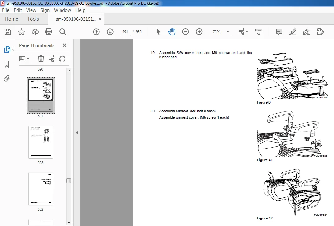
Reassembly………………………………………………………………684
Start-up Procedures………………………………………………………692
Travel Control Valve (with Damper) SP002381…………………………………….693
Safety Instructions………………………………………………………697
Applicable Models………………………………………………………..697
General Description………………………………………………………698
Theory of Operation…………………………………………………..698
Pressure Reducing Valve……………………………………………….699
Operating Theory of Damper Mechanism……………………………………700
Causes of Faults and Measures……………………………………………..701
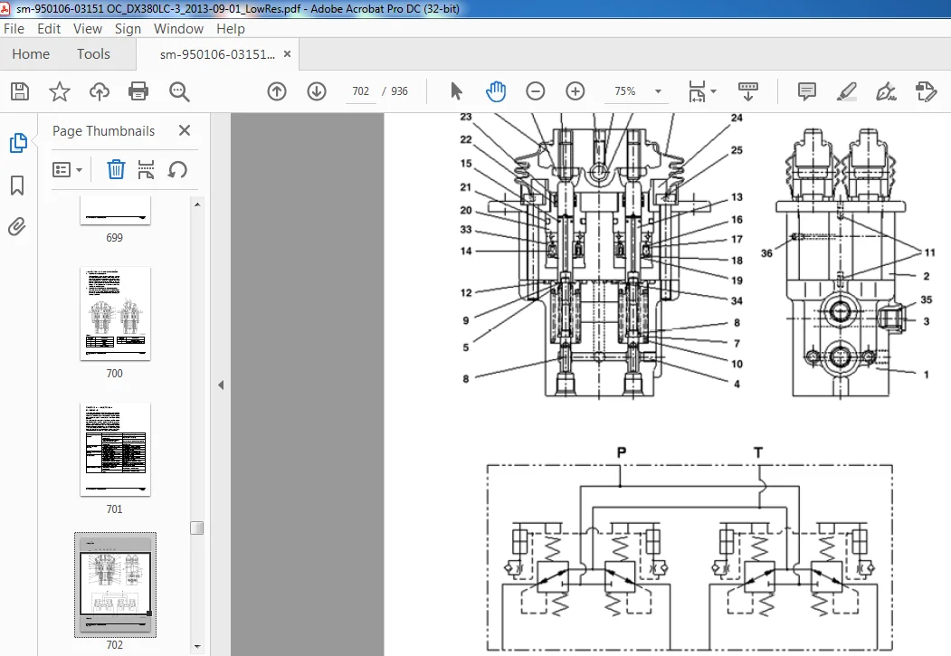
Parts List…………………………………………………………..702
Specification………………………………………………………..704
Torques……………………………………………………………..704
Disassembly……………………………………………………………..708
Cleaning and Inspection (Wear Limits and Tolerances)…………………………710
Reassembly………………………………………………………………711
Installation…………………………………………………………….716
Start-up Procedures………………………………………………………719
Solenoid Valve Assembly SP003121………………………………………………721
Safety Instructions………………………………………………………725
Applicable Models………………………………………………………..725
Solenoid Valve…………………………………………………………..726
Parts List…………………………………………………………..726
Functions of Solenoid Valve Assembly……………………………………727
Assembly Diagram and Tools Required…………………………………….728
Cautions During Disassembly and Reassembly………………………………729
Solenoid Valve Diagram………………………………………………..730
Check Points and Solutions for Problems…………………………………731
Hydraulic Schematic SP003125………………………………………………….733
Safety Instructions………………………………………………………737
Applicable Models………………………………………………………..737
Electrical System……………………………………………………………….741
Electrical System SP003122……………………………………………………743
Safety Instructions………………………………………………………749
Applicable Models………………………………………………………..749
Introduction…………………………………………………………….750
Electrical Supply System………………………………………………….752
Engine Starting Circuit…………………………………………………..754
Start Operation………………………………………………………754
After Start………………………………………………………….756
Engine Preheating System………………………………………………….758
Engine Stop……………………………………………………………..760
Monitoring System………………………………………………………..763
Instrument Panel……………………………………………………..764
Functional Check……………………………………………………..764
Monitoring System Schematic……………………………………………766
Operation……………………………………………………………….768
Instruments………………………………………………………….768
Warning and Indicator Lights……………………………………………… 0
Indication of Multifunction Gauge………………………………………772
Initial Operation………………………………………………………..774
Mode Selector Switch……………………………………………………..774
Graphic Information Area Display…………………………………………..776
Overview…………………………………………………………….776
Main Menus for the Graphic Display Area…………………………………776
Menu Selector Buttons…………………………………………………776
Special Menu…………………………………………………………….809
Entering/Accessing and Exiting/Escaping Menus……………………………809
Special Menu Selections……………………………………………….810
Electronic Hydraulic Control System (EPOS)………………………………….834
Control System Schematic………………………………………………834
Power Plus Mode Control…………………………………………………..836
Operation……………………………………………………………838
Power Mode Control – Circuit Diagram……………………………………….840
Engine Control System…………………………………………………….842
Engine Control Dial………………………………………………………843
Engine Control Circuit Diagram…………………………………………….844
Automatic Deceleration Control (Auto Idle Control)…………………………..846
Engine Overheat Protection System………………………………………….848
Power Boost Mode…………………………………………………………850
Operation……………………………………………………………850
Power Boost Control – Circuit Diagram…………………………………..852
Automatic Travel Speed Control…………………………………………….854
Self-diagnostic Function………………………………………………….857
EPOS Controller………………………………………………………857
Air Conditioner System……………………………………………………859
Outline……………………………………………………………..859
Internal and External Filters………………………………………….860
Air-Conditioning System Layout…………………………………………862
Air Conditioner/heater Circuit Diagram………………………………….863
Air Conditioner/heater Unit……………………………………………864
Ambient Air Temperature Sensor…………………………………………869
Compressor…………………………………………………………..878
Receiver Dryer……………………………………………………….878
Troubleshooting………………………………………………………….879
Weight of R134a Gas Used In Machines……………………………………….881
Refrigerant System Repairs………………………………………………..882
Refrigerant Safe Handling Procedures……………………………………882
Repair and Replacement Procedure……………………………………….883
Refrigerant Recovery………………………………………………….885
Vacuuming Refrigerant System…………………………………………..885
Leakage Check………………………………………………………..887
Refrigerant Charging………………………………………………….887
Inspecting System For Leakage………………………………………….889
Wiper System…………………………………………………………….890
Wiper Circuit………………………………………………………..890
Wiper operation………………………………………………………891
Lighting System…………………………………………………………. 0
Kind of Light………………………………………………………..895
Operation……………………………………………………………895
Overload Warning Device…………………………………………………..896
Overload Warning Device Circuit Diagram…………………………………896
Electrical Schematic SP003123…………………………………………………899
Safety Instructions………………………………………………………903
Applicable Models………………………………………………………..903
Attachments…………………………………………………………………….907
Boom and Arm SP002605………………………………………………………..909
Safety Instructions………………………………………………………913
Applicable Models………………………………………………………..913
Front Attachment Pin Specifications………………………………………..914
DX380LC-3……………………………………………………………915
Front Attachment – Removal and Installation…………………………………916
Arm Removal Procedure…………………………………………………916
Boom Removal Procedure………………………………………………..918
Installation…………………………………………………………….919
Arm Installation Procedure…………………………………………….919
Boom Installation Procedure……………………………………………919
Start-up Procedures………………………………………………………920
Bucket SP002421……………………………………………………………..921
Safety Instructions………………………………………………………925
Applicable Models………………………………………………………..925
Bucket Tooth Inspection and Replacement…………………………………….926
Bucket O-ring Replacement…………………………………………………927
Bucket Shimming Procedures……………………………………………….. 0
New Bucket Installation………………………………………………. 0
Shimming Procedures for Installed Bucket…………………………….930
Attachments……………………………………………………………..931
Bucket Replacement and Reversal………………………………………..931
Replacement………………………………………………………….932
Reversal…………………………………………………………….933
Quick Coupler Operation (Optional)……………………………………..934
Securing Work Tool………………………………………………..934
Attaching Quick Coupler to Excavator………………………………..934
Releasing the Work Tool……………………………………………
Table of Contents………………………………………………………………. 6
Safety………………………………………………………………………… 8
Track Excavator Maintenance Safety SP003114……………………………………. 10
Safety Instructions……………………………………………………… 14
Applicable Models……………………………………………………….. 14
Safety Messages…………………………………………………………. 15
Signal Words………………………………………………………… 15
Other Signal Words…………………………………………………… 16
Safety Decals…………………………………………………………… 16
General………………………………………………………………… 17
Safe Operation is Operator’s Responsibility…………………………….. 17
Know Your Machine……………………………………………………. 17
Proper Work Tools and Attachments……………………………………… 17
Pressurized Fluids…………………………………………………… 18
Flying or Falling Objects…………………………………………….. 19
Personal Protective Equipment (PPE)……………………………………. 19
Correction of Machine Problems………………………………………… 19
Crushing and Cutting…………………………………………………. 20
Hot Coolant and Oils – Burn Prevention…………………………………. 21
Fire and Explosion Prevention…………………………………………. 21
Fire Extinguisher and First-Aid Kit (Emergency Medical Kit)………………. 25
Electrical System and Electrical Shock…………………………………. 25
Rollover Protective Structure (ROPS)…………………………………… 26
Transportation………………………………………………………….. 29
Obey State and Local Over-the-Road Regulations………………………….. 29
Loading and Unloading………………………………………………… 29
Transporting Machine…………………………………………………. 30
Operation………………………………………………………………. 31
Before Engine Starting……………………………………………….. 31
Work Site…………………………………………………………… 32
Mounting/Dismounting…………………………………………………. 33
Cleaning……………………………………………………………. 34
Operator Station…………………………………………………….. 34
Seat Belt…………………………………………………………… 35
Visibility Information……………………………………………….. 36
Boost Starting or Charging Engine Batteries…………………………….. 37
Swinging or Traveling………………………………………………… 39
Lifting and Digging………………………………………………….. 41
Operation on Slopes………………………………………………….. 42
Towing……………………………………………………………… 43
Attachment………………………………………………………….. 44
Equipment Lowering with Engine Stopped…………………………………. 44
Engine Stop…………………………………………………………. 44
Parking Machine……………………………………………………… 45
Preservation/Storing Machine………………………………………….. 46
Maintenance…………………………………………………………….. 48
Cleaning……………………………………………………………. 52
Proper Tools and Clothing…………………………………………….. 52
Disassembling Precautions…………………………………………….. 52
Use of Lighting……………………………………………………… 53
Fire and Explosion Prevention…………………………………………. 53
Burn Prevention……………………………………………………… 54
Rubber That Contains Fluorides………………………………………… 55
Rubber and Plastics………………………………………………….. 56
Welding Repairs……………………………………………………… 57
Warning for Counterweight and Front Attachment Removal…………………… 58
Lock Inspection Covers……………………………………………….. 59
Working on Machine…………………………………………………… 59
Accumulator…………………………………………………………. 60
Compressed Air………………………………………………………. 60
Track Tension Adjustments…………………………………………….. 61
Supports and Blocking for Work Equipment……………………………….. 61
High-pressure Lines, Tubes and Hoses…………………………………… 62
Battery…………………………………………………………….. 63
Environment and Circumstances…………………………………………….. 65
Work Site Areas Requiring Extra Caution………………………………… 65
High-voltage Cables………………………………………………….. 67
Underground Operation………………………………………………… 68
Working in Water…………………………………………………….. 68
Working in Contaminated Environment……………………………………. 68
Operation in Extreme Conditions……………………………………….. 69
Exhaust Ventilation………………………………………………….. 73
Asbestos Information…………………………………………………. 74
Silica Dust Information………………………………………………. 74
Disposal of Hazardous Materials……………………………………….. 75
Sound………………………………………………………………. 76
Vibration…………………………………………………………… 76
Specifications…………………………………………………………………. 78
Specification for DX380LC-3 SP003115………………………………………….. 80
Safety Instructions……………………………………………………… 84
Applicable Models……………………………………………………….. 84
General Description……………………………………………………… 86
Component Locations……………………………………………………… 87
General Dimensions………………………………………………………. 89
Working Range…………………………………………………………… 91
General Specifications…………………………………………………… 93
Approximate Weight of Workload Materials…………………………………… 97
Performance Tests……………………………………………………….. 99
Excavator Performance Measurements…………………………………………100
Test Conditions………………………………………………………100
Travel Speed and Travel Motor Balance (Steering Deviation) Tests…………..101
Swing Speed and Deceleration Force Test…………………………………102
Cylinder Performance Tests…………………………………………….104
General Maintenance……………………………………………………………..106
General Maintenance Instructions SP002454………………………………………108
Safety Instructions………………………………………………………112
Applicable Models………………………………………………………..112
Welding Precautions and Instructions……………………………………….113
Hydraulic System – General Precautions……………………………………..114
Maintenance Service and Repair Procedure……………………………………116
General Precautions…………………………………………………..116
Hydraulic System Cleanliness and Oil Leaks………………………………….117
Maintenance Precautions for Hydraulic System Service……………………..117
Oil Leakage Precautions……………………………………………….118
Cleaning and Inspection…………………………………………………..119
General Instructions………………………………………………….119
Bearing Inspection……………………………………………………120
Standard Torques…………………………………………………………….128
Safety Instructions………………………………………………………132
Applicable Models………………………………………………………..132
Torque Values for Standard Metric Fasteners…………………………………133
Torque Values for Standard U.S. Fasteners…………………………………..134
Type 8 Phosphate Coated Hardware…………………………………………..136
Torque Values for Hose Clamps……………………………………………..137
ORFS Swivel Nut Recommended Torque…………………………………………137
Torque Values for Split Flanges……………………………………………138
Torque Wrench Extension Tools……………………………………………..139
Torque Multiplication…………………………………………………139
Other Uses for Torque Wrench Extension Tools…………………………….140
Tightening Torque Specifications (Metric)……………………………….141
Upper Structure…………………………………………………………………144
Cabin SP003124………………………………………………………………146
Safety Instructions………………………………………………………150
Applicable Models………………………………………………………..150
Cabin Identification……………………………………………………..151
Rollover Protective Structure (ROPS)……………………………………151
Counterweight SP002606……………………………………………………….160
Safety Instructions………………………………………………………164
Applicable Models………………………………………………………..164
General…………………………………………………………………165
Warning for Counterweight and Front Attachment Removal……………………165
Installation…………………………………………………………….168
Fuel Tank SP002410…………………………………………………………..170
Safety Instructions………………………………………………………174
Applicable Models………………………………………………………..174
General Description……………………………………………………… 0
Specifications……………………………………………………….176
Start-up Procedures………………………………………………………184
Fuel Transfer Pump (Option) SP003116…………………………………………..186
Safety Instructions………………………………………………………190
Applicable Models………………………………………………………..190
Troubleshooting………………………………………………………….193
Replacement of Rotor and Vane……………………………………………..193
Swing Bearing SP002329……………………………………………………….196
Safety Instructions………………………………………………………200
Applicable Models………………………………………………………..200
Swing Bearing Maintenance…………………………………………………201
Operating Recommendation………………………………………………201
Measuring Swing Bearing Axial Play……………………………………..201
Measuring Bearing Lateral Play…………………………………………201
Swing Bearing Basic Operation………………………………………….202
Disassembly………………………………………………………….202
Assembly…………………………………………………………….204
Lower Structure and Chassis………………………………………………………206
Track Assembly SP003117………………………………………………………208
Safety Instructions………………………………………………………212
Applicable Models………………………………………………………..212
General Description………………………………………………………213
Track Tension……………………………………………………………214
Cleaning and Inspection (Wear Limits and Tolerances)…………………………216
Track Shoe…………………………………………………………..217
Lower Roller…………………………………………………………219
Upper Roller…………………………………………………………220
Front Idler………………………………………………………….221
Track Shoes and Links…………………………………………………….222
Track Removal………………………………………………………..222
Track Installation……………………………………………………223
Front Idler……………………………………………………………..225
Parts List…………………………………………………………..225
Front Idler Disassembly……………………………………………….226
Front Idler Reassembly………………………………………………..228
Lower Roller…………………………………………………………….229
Parts List…………………………………………………………..229
Lower Roller Removal………………………………………………….230
Lower Roller Disassembly………………………………………………230
Lower Roller Reassembly……………………………………………….231
Lower Roller Installation……………………………………………..232
Upper Roller…………………………………………………………….233
Parts List…………………………………………………………..233
Upper Roller Removal………………………………………………….234
Upper Roller Disassembly………………………………………………234
Upper Roller Reassembly……………………………………………….236
Track Spring and Track Adjusting Cylinder…………………………………..237
Parts List…………………………………………………………..237
Engine and Drivetrain……………………………………………………………240
Drive Coupling (Main Pump) SP003118……………………………………………242
Safety Instructions………………………………………………………246
Applicable Models………………………………………………………..246
Drive Coupling…………………………………………………………..247
Hydraulics……………………………………………………………………..250
Hydraulic System Troubleshooting, Testing and Adjustment SP003119…………………252
Safety Instructions………………………………………………………256
Applicable Models………………………………………………………..256
Hydraulic System – General Notes…………………………………………..257
Hydraulic Schematic………………………………………………………257
General Notes………………………………………………………..257
Operation of Working Components……………………………………………259
Boom Operating Circuit………………………………………………..259
Boom Up Circuit………………………………………………………259
Boom Down Circuit…………………………………………………….259
Arm Operating Circuit…………………………………………………260
Arm Crowd Circuit…………………………………………………….260
Arm Dump Circuit……………………………………………………..260
Bucket Operating Circuit………………………………………………261
Bucket Crowd Circuit………………………………………………….261
Bucket Dump Circuit…………………………………………………..261
Swing Operating Circuit……………………………………………….261
Right Swing Operating Circuit………………………………………….262
Left Swing Operating Circuit…………………………………………..262
Swing Relief Valve and Makeup Valve…………………………………….262
Travel Operating Circuit………………………………………………262
Forward Travel Circuit………………………………………………..263
Reverse Travel Circuit………………………………………………..263
Procedural Troubleshooting Baseline Recommendations………………………….264
Initial Checks and Tests to Establish Operating Condition of the Excavator….264
Pilot Pressure…………………………………………………………..265
Adjustment and Testing………………………………………………..265
Pump Swash Plate…………………………………………………………266
Adjustment and Testing………………………………………………..266
Pump EPPRV………………………………………………………………267
Adjustment and Testing………………………………………………..267
Pump Pressure……………………………………………………………268
Adjustment and Testing………………………………………………..268
Pump Regulator…………………………………………………………..269
Adjustment and Testing………………………………………………..269
Installation and Testing of Flow Meter and Flow Meter Kit…………………….271
Installation and Testing Procedures…………………………………….271
Swing System Troubleshooting………………………………………………272
Precautions/Initial Checks…………………………………………….272
Swing Relief Valve Checking and Adjustment………………………………273
Troubleshooting – Swing Gearbox……………………………………………275
Troubleshooting – Hydraulic Problems……………………………………….276
Troubleshooting – Main Pump……………………………………………….279
Troubleshooting – Control Valve……………………………………………281
Troubleshooting – Travel Control Valve……………………………………..283
Troubleshooting – Joystick Control Valve……………………………………284
Accumulator SP002455…………………………………………………………286
Safety Instructions………………………………………………………290
Applicable Models………………………………………………………..290
General Description……………………………………………………… 0
Specifications……………………………………………………….293
Center Joint (Swivel) SP002545………………………………………………..294
Safety Instructions………………………………………………………298
Applicable Models………………………………………………………..298
General Description………………………………………………………299
Parts List…………………………………………………………..299
Troubleshooting, Testing and Adjustment…………………………………….301
Inspection…………………………………………………………..301
Testing……………………………………………………………..301
Disassembly……………………………………………………………..302
Reassembly………………………………………………………………305
Cylinders SP002422…………………………………………………………..308
Safety Instructions………………………………………………………312
Applicable Models………………………………………………………..312
General Description………………………………………………………313
Theory of Operation…………………………………………………..313
Parts List…………………………………………………………..315
Disassembly……………………………………………………………..338
Reassembly………………………………………………………………343
Swing Device SP002413………………………………………………………..348
Safety Instructions………………………………………………………352
Applicable Models………………………………………………………..352
Structure and Principle of Operation……………………………………353
Cautions for Operation………………………………………………..363
Troubleshooting………………………………………………………367
Disassembly and Reassembly…………………………………………….371
Remove and Install Swing Device……………………………………………373
Removal……………………………………………………………..373
Installation…………………………………………………………376
Maintenance Guidelines………………………………………………..399
Travel Device SP002609……………………………………………………….400
Safety Instructions………………………………………………………404
Applicable Models………………………………………………………..404
Basic Structure and Drawings…………………………………………..406
Operation Principle…………………………………………………..411
Operation Instructions………………………………………………..420
Troubleshooting………………………………………………………423
Maintenance Instructions………………………………………………425
Remove and Install Travel Device…………………………………………..428
Removal……………………………………………………………..428
Disassembly………………………………………………………….429
Assembly…………………………………………………………….439
Installation…………………………………………………………456
Matters to Check After Assembly………………………………………..457
Performance Test……………………………………………………..457
Main Pump SP002415…………………………………………………………..460
Safety Instructions………………………………………………………464
Applicable Models………………………………………………………..464
Product description………………………………………………………466
Performance Description……………………………………………….466
Device Description……………………………………………………466
Manual Override………………………………………………………469
Parts List…………………………………………………………..471
Transport and storage…………………………………………………….473
Transporting the Axial Piston Unit……………………………………..473
Storing the Axial Piston Unit………………………………………….475
Installation…………………………………………………………….478
Unpacking……………………………………………………………478
Installation Conditions……………………………………………….479
Installation Position…………………………………………………481
Installing the Axial Piston Unit……………………………………….483
Commissioning……………………………………………………………495
Initial Commissioning…………………………………………………496
Recommissioning After Standstill……………………………………….501
Running-in Phase……………………………………………………..501
Maintenance and repair……………………………………………………502
Cleaning and Care…………………………………………………….502
Inspection…………………………………………………………..503
Maintenance………………………………………………………….503
Repair………………………………………………………………504
Spare Parts………………………………………………………….504
Decommissioning………………………………………………………….505
Removal and replacement…………………………………………………..505
Required Tools……………………………………………………….505
Preparing for Removal…………………………………………………505
Removing the Axial Piston Unit…………………………………………506
Preparing the Components for Storage or Further Use………………………506
Troubleshooting………………………………………………………….507
How to Proceed for Troubleshooting……………………………………..507
Malfunction Table…………………………………………………….508
Replacing seals and assembly groups………………………………………..510
Sealing the Port Plate with Valve………………………………………518
Sealing or Replacing the Pressure Reducing Valve…………………………520
Replacing the Angle Position Sensor…………………………………….522
Replacing Sealing Nuts………………………………………………..524
Tightening torques……………………………………………………….525
Slotted Screws……………………………………………………….525
Threaded Plugs……………………………………………………….526
Sealing Nuts…………………………………………………………527
Gear Pump SP002568…………………………………………………………..528
Safety Instructions………………………………………………………532
Applicable Models………………………………………………………..532
Disassembling Single Gear Pump (Opt)……………………………………….533
Reassembling Single Gear Pump (Opt)………………………………………..536
Fan Motor for Oil Cooler SP003127……………………………………………..540
Safety Instructions………………………………………………………544
Applicable Models………………………………………………………..544
Disassembly……………………………………………………………..546
Assembly………………………………………………………………..549
Preassemble………………………………………………………….549
Assembling…………………………………………………………..550
Fan Pump SP002553……………………………………………………………552
Safety Instructions………………………………………………………556
Applicable Models………………………………………………………..556
View……………………………………………………………………558
ED – Valve…………………………………………………………..558
General Repair Guidelines…………………………………………………559
Sealing Control Valve…………………………………………………….562
Disassembly……………………………………………………………..563
Overview…………………………………………………………….563
Remove Rotary Group…………………………………………………..566
Remove Shaft/Bearings…………………………………………………568
Pump Assembly……………………………………………………………572
Tools/Auxiliary Tools/ Tightening Torques…………………………………..581
Main Control Valve SP003120…………………………………………………..582
Safety Instructions………………………………………………………586
Applicable Models………………………………………………………..586
Functional Description……………………………………………………587
PC-control Concept……………………………………………………587
Main Control Block……………………………………………………588
General Information…………………………………………………..589
Function…………………………………………………………….590
Additional Functions………………………………………………….617
Specifications…………………………………………………………..631
Troubleshooting, Testing and Adjustment…………………………………631
Disassembly……………………………………………………………..634
General Repair Instructions……………………………………………634
Repair Instructions…………………………………………………..636
Reassembly………………………………………………………………654
Commissioning………………………………………………………..661
Operation……………………………………………………………663
Maintenance and Repair………………………………………………..664
Remote Control Valve (Work Lever / Joystick) SP002450……………………………671
Safety Instructions………………………………………………………675
Applicable Models………………………………………………………..675
General Description………………………………………………………677
Theory of Operation…………………………………………………..677
Parts List…………………………………………………………..678
Specifications……………………………………………………….680
Torques……………………………………………………………..680
Tools and Materials………………………………………………………680
Disassembly……………………………………………………………..681
Reassembly………………………………………………………………684
Start-up Procedures………………………………………………………692
Travel Control Valve (with Damper) SP002381…………………………………….693
Safety Instructions………………………………………………………697
Applicable Models………………………………………………………..697
General Description………………………………………………………698
Theory of Operation…………………………………………………..698
Pressure Reducing Valve……………………………………………….699
Operating Theory of Damper Mechanism……………………………………700
Causes of Faults and Measures……………………………………………..701
Parts List…………………………………………………………..702
Specification………………………………………………………..704
Torques……………………………………………………………..704
Disassembly……………………………………………………………..708
Cleaning and Inspection (Wear Limits and Tolerances)…………………………710
Reassembly………………………………………………………………711
Installation…………………………………………………………….716
Start-up Procedures………………………………………………………719
Solenoid Valve Assembly SP003121………………………………………………721
Safety Instructions………………………………………………………725
Applicable Models………………………………………………………..725
Solenoid Valve…………………………………………………………..726
Parts List…………………………………………………………..726
Functions of Solenoid Valve Assembly……………………………………727
Assembly Diagram and Tools Required…………………………………….728
Cautions During Disassembly and Reassembly………………………………729
Solenoid Valve Diagram………………………………………………..730
Check Points and Solutions for Problems…………………………………731
Hydraulic Schematic SP003125………………………………………………….733
Safety Instructions………………………………………………………737
Applicable Models………………………………………………………..737
Electrical System……………………………………………………………….741
Electrical System SP003122……………………………………………………743
Safety Instructions………………………………………………………749
Applicable Models………………………………………………………..749
Introduction…………………………………………………………….750
Electrical Supply System………………………………………………….752
Engine Starting Circuit…………………………………………………..754
Start Operation………………………………………………………754
After Start………………………………………………………….756
Engine Preheating System………………………………………………….758
Engine Stop……………………………………………………………..760
Monitoring System………………………………………………………..763
Instrument Panel……………………………………………………..764
Functional Check……………………………………………………..764
Monitoring System Schematic……………………………………………766
Operation……………………………………………………………….768
Instruments………………………………………………………….768
Warning and Indicator Lights……………………………………………… 0
Indication of Multifunction Gauge………………………………………772
Initial Operation………………………………………………………..774
Mode Selector Switch……………………………………………………..774
Graphic Information Area Display…………………………………………..776
Overview…………………………………………………………….776
Main Menus for the Graphic Display Area…………………………………776
Menu Selector Buttons…………………………………………………776
Special Menu…………………………………………………………….809
Entering/Accessing and Exiting/Escaping Menus……………………………809
Special Menu Selections……………………………………………….810
Electronic Hydraulic Control System (EPOS)………………………………….834
Control System Schematic………………………………………………834
Power Plus Mode Control…………………………………………………..836
Operation……………………………………………………………838
Power Mode Control – Circuit Diagram……………………………………….840
Engine Control System…………………………………………………….842
Engine Control Dial………………………………………………………843
Engine Control Circuit Diagram…………………………………………….844
Automatic Deceleration Control (Auto Idle Control)…………………………..846
Engine Overheat Protection System………………………………………….848
Power Boost Mode…………………………………………………………850
Operation……………………………………………………………850
Power Boost Control – Circuit Diagram…………………………………..852
Automatic Travel Speed Control…………………………………………….854
Self-diagnostic Function………………………………………………….857
EPOS Controller………………………………………………………857
Air Conditioner System……………………………………………………859
Outline……………………………………………………………..859
Internal and External Filters………………………………………….860
Air-Conditioning System Layout…………………………………………862
Air Conditioner/heater Circuit Diagram………………………………….863
Air Conditioner/heater Unit……………………………………………864
Ambient Air Temperature Sensor…………………………………………869
Compressor…………………………………………………………..878
Receiver Dryer……………………………………………………….878
Troubleshooting………………………………………………………….879
Weight of R134a Gas Used In Machines……………………………………….881
Refrigerant System Repairs………………………………………………..882
Refrigerant Safe Handling Procedures……………………………………882
Repair and Replacement Procedure……………………………………….883
Refrigerant Recovery………………………………………………….885
Vacuuming Refrigerant System…………………………………………..885
Leakage Check………………………………………………………..887
Refrigerant Charging………………………………………………….887
Inspecting System For Leakage………………………………………….889
Wiper System…………………………………………………………….890
Wiper Circuit………………………………………………………..890
Wiper operation………………………………………………………891
Lighting System…………………………………………………………. 0
Kind of Light………………………………………………………..895
Operation……………………………………………………………895
Overload Warning Device…………………………………………………..896
Overload Warning Device Circuit Diagram…………………………………896
Electrical Schematic SP003123…………………………………………………899
Safety Instructions………………………………………………………903
Applicable Models………………………………………………………..903
Attachments…………………………………………………………………….907
Boom and Arm SP002605………………………………………………………..909
Safety Instructions………………………………………………………913
Applicable Models………………………………………………………..913
Front Attachment Pin Specifications………………………………………..914
DX380LC-3……………………………………………………………915
Front Attachment – Removal and Installation…………………………………916
Arm Removal Procedure…………………………………………………916
Boom Removal Procedure………………………………………………..918
Installation…………………………………………………………….919
Arm Installation Procedure…………………………………………….919
Boom Installation Procedure……………………………………………919
Start-up Procedures………………………………………………………920
Bucket SP002421……………………………………………………………..921
Safety Instructions………………………………………………………925
Applicable Models………………………………………………………..925
Bucket Tooth Inspection and Replacement…………………………………….926
Bucket O-ring Replacement…………………………………………………927
Bucket Shimming Procedures……………………………………………….. 0
New Bucket Installation………………………………………………. 0
Shimming Procedures for Installed Bucket…………………………….930
Attachments……………………………………………………………..931
Bucket Replacement and Reversal………………………………………..931
Replacement………………………………………………………….932
Reversal…………………………………………………………….933
Quick Coupler Operation (Optional)……………………………………..934
Securing Work Tool………………………………………………..934
Attaching Quick Coupler to Excavator………………………………..934
Releasing the Work Tool……………………………………………936
DOOSAN DX380LC-3 (OCEANNAI) EXCAVATOR SHOP MANUAL 950106-03151OC – PDF DOWNLOAD:
IMAGES PREVIEW OF THE MANUAL:
PLEASE NOTE:
- This is the SAME exact manual used by your dealers to fix your vehicle.
- The same can be yours in the next 2-3 mins as you will be directed to the download page immediately after paying for the manual.
- Any queries / doubts regarding your purchase, please feel free to contact [email protected]
R.D