Doosan DX85R 3 Excavator Shop Manual – PDF DOWNLOAD
Original price was: $65.95.$31.95Current price is: $31.95.
Doosan DX85R 3 Excavator Shop Manual – PDF DOWNLOAD
Serial Number 1001 and Up
950106-01030 E-2
August 2015
Description
Doosan DX85R 3 Excavator Shop Manual – PDF DOWNLOAD
DESCRIPTION:
Doosan DX85R 3 Excavator Shop Manual – PDF DOWNLOAD
950106-01030 E-2
August 2015
GENERAL:
Proper Work Tools and Attachments:
- Only use work tools and attachments that are recommended by DOOSAN for use on DOOSAN machines. When installing and using optional attachments, read instruction manual for attachment, and general information related to attachments in this manual.
- Because DOOSAN cannot anticipate, identify or test all attachments that owners may want to install on their machines, contact DOOSAN for written authorization and approval of attachments, and their compatibility with optional kits. Attachments and attachment control systems that are compatible with the machine are required for safe and reliable machine operation.
- Do not exceed maximum operating weight (machine weight plus attachment) that is listed on ROPS certification plate. Make sure that all guards and shields are in place on machine and on work tool. Depending on type or combination of work equipment, there is a potential that work equipment could interfere with the cabin or other parts of machine.
- Before using unfamiliar work equipment, check if there is any potential of interference, and operate with caution. While you are performing any maintenance, testing, or adjustments to attachments, stay clear of the following areas: cutting edges, pinch points, and crushing surfaces.
- Never use attachment as a work platform or manlift. Contact your DOOSAN distributor about auxiliary hydraulic kits for attachments installation. If you are in doubt about compatibility of a particular atta
- Immediately after operations are stopped, coolant, engine oil, and hydraulic oil are at their highest temperatures and the radiator and hydraulic tank are still under pressure. Always wait for temperature to cool down.
- Follow specified procedures when attempting to remove caps, drain oil or coolant, or replacing filters. Always wait for temperature to cool down, and follow specified procedures when performing these operations. Failure to do so can result in death or serious injury.
- When pressurized air and/or pressurized water is used for cleaning, wear protective clothing, protective shoes, and eye protection. Eye protection includes goggles or a protective face shield. Pressure can be trapped in a hydraulic system and must be relieved before maintenance is started.
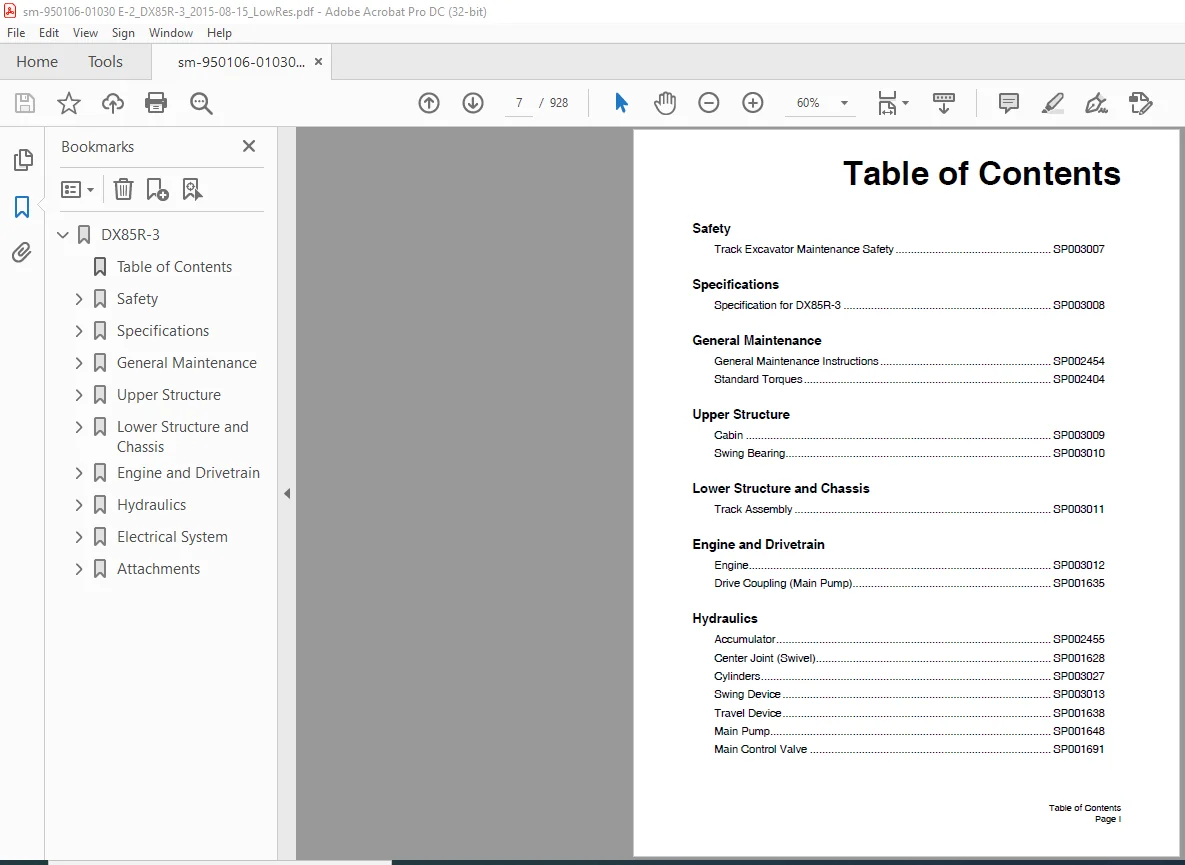
TABLE OF CONTENTS:
Doosan DX85R 3 Excavator Shop Manual – PDF DOWNLOAD
DX85R-3……………………………………………………………………………………… 0
Table of Contents…………………………………………………………………………. 7
Safety…………………………………………………………………………………… 9
Track Excavator Maintenance Safety SP003007………………………………………………. 11
Safety Instructions………………………………………………………………… 15
Applicable Models………………………………………………………………….. 15
Safety Messages……………………………………………………………………. 16
Signal Words…………………………………………………………………… 16
Other Signal Words……………………………………………………………… 17
Safety Decals……………………………………………………………………… 17
General…………………………………………………………………………… 18
Safe Operation is Operator’s Responsibility……………………………………….. 18
Know Your Machine………………………………………………………………. 18
Proper Work Tools and Attachments………………………………………………… 19
Pressurized Fluids……………………………………………………………… 19
Flying or Falling Objects……………………………………………………….. 20
Personal Protective Equipment (PPE)………………………………………………. 21
Correction of Machine Problems…………………………………………………… 21
Crushing and Cutting……………………………………………………………. 21
Hot Coolant and Oils – Burn Prevention……………………………………………. 22
Fire and Explosion Prevention……………………………………………………. 23
Maintenance………………………………………………………………… 23
Operation………………………………………………………………….. 23
Electrical…………………………………………………………………. 24
Hydraulic System……………………………………………………………. 24
Fueling……………………………………………………………………. 25
Never Use Ether Starting Aids………………………………………………… 25
Welding and Grinding………………………………………………………… 25
If a Fire Occurs……………………………………………………………. 26
Fire Extinguisher and First-Aid Kit (Emergency Medical Kit)…………………………. 26
Electrical System and Electrical Shock……………………………………………. 27
Roll-over Protective Structure (ROPS)…………………………………………….. 27
Protecting Cabin from Flying or Falling Objects (Optional)………………………. 29
Emergency Exit from Operator’s Station………………………………………… 30
Transportation…………………………………………………………………….. 31
Obey State and Local Over-the-Road Regulations…………………………………….. 31
Loading and Unloading…………………………………………………………… 31
Transporting Machine……………………………………………………………. 32
Operation…………………………………………………………………………. 33
Before Engine Starting………………………………………………………….. 33
Machine Condition…………………………………………………………… 33
Work Site……………………………………………………………………… 34
Mounting/Dismounting……………………………………………………………. 34
Cleaning………………………………………………………………………. 35
Operator Station……………………………………………………………….. 35
Seat Belt……………………………………………………………………… 36
Visibility Information………………………………………………………….. 37
Work Site Rules…………………………………………………………….. 38
Boost Starting or Charging Engine Batteries……………………………………….. 38
Swinging or Traveling…………………………………………………………… 40
Lifting and Digging…………………………………………………………….. 42
Operation on Slopes…………………………………………………………….. 43
Towing………………………………………………………………………… 44
Attachment…………………………………………………………………….. 45
Equipment Lowering with Engine Stopped……………………………………………. 45
Engine Stop……………………………………………………………………. 45
Parking Machine………………………………………………………………… 46
Preservation/Storing Machine…………………………………………………….. 47
Check After Long-term Parking………………………………………………… 48
Maintenance……………………………………………………………………….. 49
Cleaning………………………………………………………………………. 53
Proper Tools and Clothing……………………………………………………….. 53
Disassembling Precautions……………………………………………………….. 53
Use of Lighting………………………………………………………………… 54
Fire and Explosion Prevention……………………………………………………. 54
Burn Prevention………………………………………………………………… 55
Rubber That Contains Fluorides…………………………………………………… 56
Rubber and Plastics…………………………………………………………….. 57
Waste Hazardous to the Environment……………………………………………. 57
Check List After Fire……………………………………………………….. 57
Welding Repairs………………………………………………………………… 58
Preparation for Electrical Welding On Body Structure……………………………. 59
Warning for Counterweight and Front Attachment Removal……………………………… 59
Lock Inspection Covers………………………………………………………….. 60
Working on Machine……………………………………………………………… 60
Accumulator……………………………………………………………………. 61
Compressed Air…………………………………………………………………. 61
Track Tension Adjustments……………………………………………………….. 62
Supports and Blocking for Work Equipment………………………………………….. 62
High-pressure Lines, Tubes and Hoses……………………………………………… 63
Battery……………………………………………………………………….. 64
Battery Hazard Prevention……………………………………………………. 64
Environment and Circumstances……………………………………………………….. 66
Work Site Areas Requiring Extra Caution…………………………………………… 66
Digging Under an Overhang……………………………………………………. 66
Deep Digging……………………………………………………………….. 66
Drop-off or Edge……………………………………………………………. 67
Poor Visibility…………………………………………………………….. 67
Loose or Soft Ground………………………………………………………… 67
High-voltage Cables…………………………………………………………….. 68
Underground Operation…………………………………………………………… 69
Working in Water……………………………………………………………….. 69
Working in Contaminated Environment………………………………………………. 69
Operation in Extreme Conditions………………………………………………….. 70
Operation In Extreme Cold……………………………………………………. 70
Operation in Extreme Heat……………………………………………………. 71
Operation In Dusty and Sandy Areas……………………………………………. 72
Operation in Rainy or Humid Conditions………………………………………… 72
Operation in Saltwater Areas…………………………………………………. 73
Operation at High Altitudes………………………………………………….. 73
Operation During Electrical Storms……………………………………………. 73
Exhaust Ventilation…………………………………………………………….. 74
Ventilation for Enclosed Area………………………………………………… 74
Asbestos Information……………………………………………………………. 74
Silica Dust Information…………………………………………………………. 75
Disposal of Hazardous Materials………………………………………………….. 75
Sound…………………………………………………………………………. 76
Vibration……………………………………………………………………… 76
Specifications……………………………………………………………………………. 77
Specification for DX85R-3 SP003008………………………………………………………. 79
Safety Instructions………………………………………………………………… 83
Applicable Models………………………………………………………………….. 83
General Description………………………………………………………………… 85
Component Locations………………………………………………………………… 86
General Dimensions…………………………………………………………………. 88
One – Piece Boom……………………………………………………………….. 88
Two – Piece Boom……………………………………………………………….. 90
Working Range……………………………………………………………………… 92
One – Piece Boom……………………………………………………………….. 92
Two – Piece Boom……………………………………………………………….. 94
General Specifications……………………………………………………………… 96
Engine Performance Curves (Per DIN 6270 Standard)……………………………………… 97
Approximate Weight of Workload Materials……………………………………………… 98
Performance Tests…………………………………………………………………..100
Excavator Performance Standards………………………………………………………101
Test Conditions…………………………………………………………………101
Travel Speed and Travel Motor Balance (Steering Deviation) Tests……………………..101
Speed Test………………………………………………………………….101
Travel Deviation…………………………………………………………….102
Swing Speed and Deceleration Force Test……………………………………………103
Swing Speed Test…………………………………………………………….103
Swing Deceleration Force Test…………………………………………………103
Cylinder Performance Tests……………………………………………………….104
Hydraulic Cylinder…………………………………………………………..104
Boom Cylinders Test………………………………………………………….104
Arm Cylinder Test……………………………………………………………104
Bucket Cylinder Test…………………………………………………………104
Hydraulic Cylinder Natural Drop Test…………………………………………..104
Travel Motor Jack-up Test…………………………………………………….104
General Maintenance………………………………………………………………………..105
General Maintenance Instructions SP002454…………………………………………………107
Safety Instructions…………………………………………………………………111
Applicable Models…………………………………………………………………..111
Welding Precautions and Instructions………………………………………………….112
Hydraulic System – General Precautions………………………………………………..113
Maintenance Service and Repair Procedure………………………………………………115
General Precautions……………………………………………………………..115
Hydraulic System Cleanliness and Oil Leaks…………………………………………….116
Maintenance Precautions for Hydraulic System Service………………………………..116
Oil Leakage Precautions………………………………………………………….117
Cleaning and Inspection……………………………………………………………..118
General Instructions…………………………………………………………….118
Bearing Inspection………………………………………………………………119
Standard Torques SP002404……………………………………………………………….127
Safety Instructions…………………………………………………………………131
Applicable Models…………………………………………………………………..131
Torque Values for Standard Metric Fasteners……………………………………………132
Torque Values for Standard U.S. Fasteners……………………………………………..133
Type 8 Phosphate Coated Hardware……………………………………………………..135
Torque Values for Hose Clamps………………………………………………………..136
ORFS Swivel Nut Recommended Torque……………………………………………………136
Torque Values for Split Flanges………………………………………………………137
Torque Wrench Extension Tools………………………………………………………..138
Torque Multiplication……………………………………………………………138
Other Uses for Torque Wrench Extension Tools……………………………………….139
Tightening Torque Specifications (Metric)………………………………………….140
Upper Structure……………………………………………………………………………143
Cabin SP003009…………………………………………………………………………145
Safety Instructions…………………………………………………………………149
Applicable Models…………………………………………………………………..149
Cabin Identification………………………………………………………………..150
Rollover Protective Structure (ROPS)………………………………………………150
Installation……………………………………………………………………….157
Swing Bearing SP003010………………………………………………………………….161
Safety Instructions…………………………………………………………………165
Applicable Models…………………………………………………………………..165
Swing Bearing Maintenance……………………………………………………………166
Operating Recommendation…………………………………………………………166
Measuring Swing Bearing Axial Play………………………………………………..166
Measuring Bearing Lateral Play……………………………………………………166
Swing Bearing Basic Operation…………………………………………………….167
Disassembly…………………………………………………………………….167
Assembly……………………………………………………………………….169
Lower Structure and Chassis…………………………………………………………………171
Track Assembly SP003011…………………………………………………………………173
Safety Instructions…………………………………………………………………177
Applicable Models…………………………………………………………………..177
Tracks…………………………………………………………………………….178
Specification and Construction……………………………………………………178
Track Tension………………………………………………………………………179
Cleaning and Inspection (Wear Limits and Tolerances)……………………………………182
Rubber Track……………………………………………………………………183
Steel Track…………………………………………………………………….184
Track Frame Spring………………………………………………………………185
Idler………………………………………………………………………….186
Lower Roller……………………………………………………………………189
Upper Roller……………………………………………………………………191
Sprocket……………………………………………………………………….192
Idler……………………………………………………………………………..193
Parts List……………………………………………………………………..193
Disassembly…………………………………………………………………….194
Assembly……………………………………………………………………….196
Lower Roller……………………………………………………………………….198
Steel Track…………………………………………………………………….198
Disassembly…………………………………………………………………….199
Assembly……………………………………………………………………….200
Rubber Track……………………………………………………………………202
Disassembly…………………………………………………………………….203
Assembly……………………………………………………………………….204
Upper Roller……………………………………………………………………….206
Parts List……………………………………………………………………..206
Disassembly…………………………………………………………………….207
Assembly……………………………………………………………………….208
Track Removal and Installation……………………………………………………….210
Track Removal…………………………………………………………………..210
Track Installation………………………………………………………………211
Replacement of Rubber Tracks with Steel Tracks……………………………………..212
Replacement of Steel Tracks with Rubber Tracks……………………………………..213
Track Spring and Track Adjusting Cylinder……………………………………………..214
Parts List……………………………………………………………………..214
Disassembly…………………………………………………………………….215
Reassembly……………………………………………………………………..215
Sprocket…………………………………………………………………………..216
Disassembly…………………………………………………………………….216
Reassembly……………………………………………………………………..216
Engine and Drivetrain………………………………………………………………………217
Engine SP003392 ……………………………………………………………………….219
Safety Instructions…………………………………………………………………225
Applicable Models…………………………………………………………………..225
Safety…………………………………………………………………………….226
Safety Precautions………………………………………………………………226
General Service Information………………………………………………………….253
Component Identification…………………………………………………………253
Location of Labels………………………………………………………………254
Function of Major Engine Components……………………………………………….255
Main Electronic Control Components and Features…………………………………….256
Function of Cooling System Components……………………………………………..257
Installation Position Of Sensors………………………………………………….258
Supply Pump…………………………………………………………………258
Rail Pressure Sensor…………………………………………………………259
Crank Rotation Sensor………………………………………………………..259
Cam Speed Sensor…………………………………………………………….260
Water Temperature Sensor……………………………………………………..260
New Air Temperature Sensor……………………………………………………261
Diesel Particulate Filter (DPF) Intermediate/lnlet, Exhaust Air Temperature Sensor….262
Diesel Particulate Filter (DPF) Differential Pressure Sensor……………………..263
Intake/Exhaust Pressure Sensor………………………………………………..264
Intake Air Temperature Sensor…………………………………………………264
EGR Gas Temperature Sensor……………………………………………………265
EGR Valve…………………………………………………………………..265
Intake Air Throttles…………………………………………………………266
Acceleration Sensor (YANMAR Standard)………………………………………….267
Diesel Fuel…………………………………………………………………….268
Diesel Fuel Specifications……………………………………………………268
Filling The Fuel Tank………………………………………………………..270
Priming the Fuel System………………………………………………………272
Engine Oil……………………………………………………………………..273
Engine Oil Specifications…………………………………………………….273
Engine Oil Viscosity…………………………………………………………274
Checking Engine Oil………………………………………………………….274
Adding Engine Oil……………………………………………………………274
Engine Coolant………………………………………………………………….275
Engine Coolant Specifications…………………………………………………276
Filling Radiator with Engine Coolant…………………………………………..277
Engine Coolant Capacity (Typical)……………………………………………..277
Specifications………………………………………………………………….278
Description of Model Number…………………………………………………..278
Engine General Specifications…………………………………………………278
Principal Engine Specifications…………………………………………………..279
Set Output Listed by Rotation…………………………………………………279
Engine Service Standards…………………………………………………………280
Tightening Torques for Standard Bolts and Nuts……………………………………..280
Periodic Maintenance………………………………………………………………..282
Before You Begin Servicing……………………………………………………….282
Introduction……………………………………………………………………282
The Importance of Periodic Maintenance…………………………………………282
Performing Periodic Maintenance……………………………………………….282
DOOSAN Replacement Parts……………………………………………………..283
Required EPA/ARB Maintenance – USA Only………………………………………..283
EPA/ARB Installation Requirements -USA Only…………………………………….283
Periodic Maintenance Schedule…………………………………………………….284
Periodic Maintenance Procedures…………………………………………………..286
After Initial 50 Hours of Operation……………………………………………286
Every 50 Hours of Operation…………………………………………………..290
Every 250 Hours of Operation………………………………………………….294
Every 500 Hours of Operation………………………………………………….298
Every 1,000 Hours of Operation………………………………………………..302
Every 1,500 Hours of Operation………………………………………………..304
Every 2,000 Hours of Operation………………………………………………..305
Every 3,000 Hours of Operation………………………………………………..306
Engine…………………………………………………………………………….308
Before You Begin Servicing……………………………………………………….308
Introduction……………………………………………………………………308
Cylinder Head Specifications……………………………………………………..308
Adjustment Specifications…………………………………………………….308
Cylinder Head……………………………………………………………….308
Intake/Exhaust Valve and Guide………………………………………………..309
Push Rod……………………………………………………………………309
Valve Spring………………………………………………………………..309
Rocker Arm and Shaft…………………………………………………………309
Camshaft and Timing Gear Train Specifications………………………………………310
Camshaft……………………………………………………………………310
Idler Gear Shaft and Bushing………………………………………………….310
Timing Gear Backlash…………………………………………………………310
Crankshaft and Piston Specifications………………………………………………311
Crankshaft………………………………………………………………….311
Thrust Bearing………………………………………………………………311
Piston……………………………………………………………………..311
Piston Ring…………………………………………………………………312
Connecting Rod………………………………………………………………312
Tappet……………………………………………………………………..313
Cylinder Block Specifications…………………………………………………….313
Cylinder Block………………………………………………………………313
Special Torque Chart…………………………………………………………….314
Torque for Bolts and Nuts…………………………………………………….314
Special Service Tools……………………………………………………………316
Measuring Instruments……………………………………………………………319
Cylinder Head…………………………………………………………………..322
Cylinder Head Components……………………………………………………..322
Components of a Cylinder Head…………………………………………………323
Disassembly of Cylinder Head………………………………………………….324
Cleaning of Cylinder Head Components…………………………………………..328
Inspection of Cylinder Head Components…………………………………………328
Reassembly of Cylinder Head…………………………………………………..333
Measuring and Adjusting Valve Clearance……………………………………………338
Crankshaft and Camshaft Components………………………………………………..340
Disassembly of Engine………………………………………………………..342
Disassembly of Camshaft and Timing Components…………………………………..343
Disassembly of Crankshaft and Piston Components…………………………………348
Inspection of Crankshaft and Camshaft Components………………………………..352
Honing and Boring……………………………………………………………358
Reassembly of Crankshaft and Piston Components………………………………….359
Reassembly of Camshaft and Timing Components……………………………………365
Final Reassembly of Engine……………………………………………………369
EGR System……………………………………………………………………..370
EGR System………………………………………………………………….370
Fuel System………………………………………………………………………..377
Before You Begin Servicing……………………………………………………….377
Fuel System Specifications……………………………………………………….379
Torque Chart for Major Bolts and Nuts………………………………………….379
Fuel System Diagram……………………………………………………………..380
Fuel System Components…………………………………………………………..381
Removal of Common Rail……………………………………………………….382
Reassembly of Common Rail…………………………………………………….384
Removal of Injector………………………………………………………….385
Reassembly of Injector……………………………………………………….386
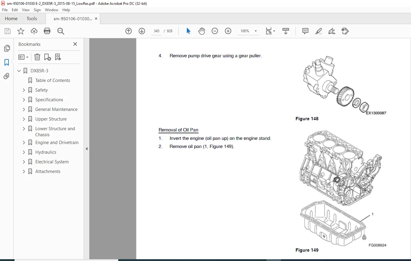
Removal of Supply Pump……………………………………………………….388
Reassembly of Supply Pump…………………………………………………….389
Cooling System……………………………………………………………………..391
Before You Begin Servicing……………………………………………………….391
Introduction……………………………………………………………………391
Cooling System Diagram…………………………………………………………..392
Engine Coolant Pump Components……………………………………………………393
Engine Coolant System Check………………………………………………………394
Engine Coolant Pump……………………………………………………………..394
Disassembly of Engine Coolant Pump…………………………………………….396
Cleaning and Inspection………………………………………………………396
Reassembly of Engine Coolant Pump……………………………………………..397
Installation of Engine Coolant Pump……………………………………………397
Lubrication System………………………………………………………………….399
Before You Begin Servicing……………………………………………………….399
Introduction……………………………………………………………………399
Oil Pump Service Information……………………………………………………..399
Lubrication System Diagram……………………………………………………….400
Checking Engine Oil Pressure……………………………………………………..401
Trochoid Oil Pump……………………………………………………………….401
4TNV98C Oil Pump Components…………………………………………………..401
Disassembly of Oil Pump………………………………………………………402
Cleaning and Inspection………………………………………………………403
Reassembly of Oil Pump……………………………………………………….404
Starter Motor………………………………………………………………………405
Before You Begin Servicing……………………………………………………….405
Introduction……………………………………………………………………405
Starter Motor Information………………………………………………………..405
4TNV98C – Standard and Optional……………………………………………….405
Starter Motor Specifications……………………………………………………..406
Starter Motor Troubleshooting…………………………………………………….407
Starter Motor Components…………………………………………………………408
Starter Motor…………………………………………………………………..409
Removal of Starter Motor……………………………………………………..409
Disassembly of Starter Motor………………………………………………….409
Cleaning and Inspection………………………………………………………412
Reassembly of Starter Motor…………………………………………………..417
Check Pinion Projection Length………………………………………………..419
No-Load Test………………………………………………………………..420
Installation of Starter Motor…………………………………………………420
Alternator…………………………………………………………………………421
Before You Begin Servicing……………………………………………………….421
Introduction……………………………………………………………………421
Dynamo and Alternator Information…………………………………………………421
Standard and Optional Dynamos…………………………………………………421
Standard and Optional Alternators……………………………………………..421
Alternator Specifications………………………………………………………..422
Dynamo Specifications……………………………………………………………422
Alternator Troubleshooting……………………………………………………….423
Alternator Components……………………………………………………………424
Alternator Wiring Diagram………………………………………………………..426
Alternator Standard Output……………………………………………………….427
Alternator……………………………………………………………………..428
Removal of Alternator………………………………………………………..428
Disassembly of Alternator…………………………………………………….429
Reassembly of Alternator……………………………………………………..431
Installation of Alternator……………………………………………………433
Dynamo Component Location………………………………………………………..434
Dynamo Wiring Diagram……………………………………………………………435
Operation of Dynamo……………………………………………………………..435
Dynamo Standard Output…………………………………………………………..436
Testing of Dynamo……………………………………………………………….437
Testing Stator Coil Continuity………………………………………………..437
Testing Stator Coil Short-to-Ground……………………………………………437
Testing Dynamo Regulated Output……………………………………………….437
Dynamo…………………………………………………………………………438
Removal of Dynamo……………………………………………………………438
Disassembly of Dynamo………………………………………………………..438
Reassembly of Dynamo…………………………………………………………439
Installation of Dynamo……………………………………………………….440
Electronic Control System……………………………………………………………441
Before You Begin Servicing……………………………………………………….441
Introduction……………………………………………………………………441
Electronic Control System………………………………………………………..441
Diesel Particulate Filter (DPF)…………………………………………………..443
Electronic Control Harness Connections…………………………………………….448
Electrical Wiring…………………………………………………………………..457
Electrical Wiring Precautions…………………………………………………….457
Electrical Wire Resistance……………………………………………………….458
Battery Cable Resistance…………………………………………………………459
Electrical Wire Sizes – Voltage Drop………………………………………………460
Conversion of AWG to European Standards……………………………………………461
Troubleshooting…………………………………………………………………….462
Special Service Tools……………………………………………………………462
Measured Value and Troubleshooting………………………………………………..462
Quick Reference Table for Troubleshooting………………………………………….462
Failure Diagnosis Table………………………………………………………….463
Drive Coupling (Main Pump) SP001635………………………………………………………469
Safety Instructions…………………………………………………………………473
Applicable Models…………………………………………………………………..473
General Description…………………………………………………………………474
Installation of Drive Coupling……………………………………………………….475
Installation Procedure…………………………………………………………..475
Precaution……………………………………………………………………..475
Hydraulics………………………………………………………………………………..477
Accumulator SP002455……………………………………………………………………479
Safety Instructions…………………………………………………………………483
Applicable Models…………………………………………………………………..483
General Description………………………………………………………………… 0
Specifications………………………………………………………………….486
Center Joint (Swivel) SP001628…………………………………………………………..487
Safety Instructions…………………………………………………………………491
Applicable Models…………………………………………………………………..491
General Description…………………………………………………………………492
Parts List……………………………………………………………………..492
Disassembly………………………………………………………………………..493
Reassembly…………………………………………………………………………496
Center Joint Assembly……………………………………………………………….498
Cylinders SP003027……………………………………………………………………..499
Safety Instructions…………………………………………………………………503
Applicable Models…………………………………………………………………..503
General Description…………………………………………………………………504
Theory of Operation……………………………………………………………..504
Parts List……………………………………………………………………..506
Boom Cylinder……………………………………………………………….506
Boom Swing Cylinder………………………………………………………….512
Disassembly………………………………………………………………………..522
Reassembly…………………………………………………………………………527
Swing Device SP003013…………………………………………………………………..531
Safety Instructions…………………………………………………………………535
Applicable Models…………………………………………………………………..535
Indication of Type………………………………………………………………….536
Specifications……………………………………………………………………..537
Structure and Principle of Operation………………………………………………….538
Parts List……………………………………………………………………..538
Principle of Operation…………………………………………………………..540
Hydraulic Motor……………………………………………………………..540
Valve Casing………………………………………………………………..541
Instructions Before Operation………………………………………………………..544
Inspection……………………………………………………………………..544
External Load at the End of Shaft…………………………………………………544
Hydraulic Oil and Temperature Range……………………………………………….544
Filter…………………………………………………………………………545
Installation and Piping………………………………………………………….546
Oil Filling and Air Ventilation…………………………………………………..546
Instructions Before Starting to Operate……………………………………………546
Troubleshooting…………………………………………………………………….547
General Instructions…………………………………………………………….547
Examination of Hydraulic Motor……………………………………………………547
Troubleshooting…………………………………………………………………548
Disassembling and Assembling…………………………………………………………550
Tightening Torque of Bolts……………………………………………………….550
Necessary Tools…………………………………………………………………550
Disassembly Procedure……………………………………………………………552
Precautions Before Disassembly………………………………………………..552
Disassembly Swing Motor………………………………………………………552
Assembly Swing Motor…………………………………………………………558
Disassembly of Reduction Gear…………………………………………………564
Assembly of Reduction Gear……………………………………………………567
Maintenance Instructions…………………………………………………………571
Part Replacement Standards for Reduction Gear…………………………………..572
Standard of Sliding Surface Correction…………………………………………573
Travel Device SP001638………………………………………………………………….575
Safety Instructions…………………………………………………………………579
Applicable Models…………………………………………………………………..579
Parts List…………………………………………………………………………580
Exploded Views of Hydraulic Gears…………………………………………………582
General……………………………………………………………………………584
Configuration…………………………………………………………………..584
Features……………………………………………………………………….584
Structural Diagram of the Traveling System…………………………………………585
Reduction Gear………………………………………………………………585
Hydraulic Motor……………………………………………………………..586
Control Unit………………………………………………………………..587
Structural Diagram of the Axial Piston Motor……………………………………….588
Operating Principle…………………………………………………………………589
When Traveling………………………………………………………………….589
When Counterbalance Operates……………………………………………………..590
When Brake Functions…………………………………………………………….591
Operating Principle of Parking Brake………………………………………………592
2 Speed Limiting Function………………………………………………………..593
Special Tools and Materials………………………………………………………….595
Standard Tools………………………………………………………………….595
Bolts………………………………………………………………………….595
Equipment and Materials………………………………………………………….596
Manufacturing Tools……………………………………………………………..596
Travel Motor Workbench……………………………………………………….596
Fixture…………………………………………………………………….596
Holder (I)………………………………………………………………….597
Holder (II)…………………………………………………………………597
Press Tool………………………………………………………………….597
Steel Rod (I)……………………………………………………………….598
Bearing Preload Adjuster……………………………………………………..598
Thrust Washer Installation Tool (Carrier (3))…………………………………..600
Thrust Washer Installation Tool (Spindle (2))…………………………………..600
Tightening Torque……………………………………………………………….601
Weight Table……………………………………………………………………601
Disassembly………………………………………………………………………..602
Preparations……………………………………………………………………602
Workbench Preparations……………………………………………………….602
Preparation of Tools and Materials…………………………………………….602
General Suggestions When Working………………………………………………….602
Disassembly Procedure……………………………………………………………603
Washing GM motor…………………………………………………………….603
GM Motor Installation………………………………………………………..604
Lubricating Oil Extraction……………………………………………………604
Cover Removal……………………………………………………………….605
Sun Gear (1) Removal…………………………………………………………605
Carrier Assembly Removal……………………………………………………..605
Planetary Gear (2) Removal……………………………………………………606
Rear Flange Removal………………………………………………………….607
Disassembly of the Rear Flange Mounting the Parts……………………………….609
Disassemble SRV into Rear Flange………………………………………………610
Disassemble Brake Valve Part into Rear Flange…………………………………..611
Removing Pilot Valve into Rear Flange………………………………………….612
Disassembly of the Parking Brake………………………………………………613
Disassembly of the Hydraulic Motor…………………………………………….613
Removal of the Spring Inside the Cylinder Block…………………………………615
Removal of the Swash Plate……………………………………………………615
Removal of the Ball Bearing…………………………………………………..616
Removal of the Ring Nut………………………………………………………616
Ball Bearing Removal…………………………………………………………618
Removal of the Spindle Fittings……………………………………………….619
Washing…………………………………………………………………….619
Finish Washing………………………………………………………………620
Service Preparations………………………………………………………………..621
Seals………………………………………………………………………….621
Service Standards for Parts Subject to Wear………………………………………..621
Assembly…………………………………………………………………………..623
Preparation…………………………………………………………………….623
General Suggestions When Working………………………………………………….623
Assembly Procedure………………………………………………………………624
Hub Section Reassembly……………………………………………………….624
Spindle Assembly…………………………………………………………….625
Assembling Spindle Fittings…………………………………………………..627
Installing Shaft…………………………………………………………….628
Assembly of Cylinder Block Interior……………………………………………628
Assembly of the Hydraulic Motor Part…………………………………………..629
Assembly of Parking Brake Section……………………………………………..630
Assembly of the Brake Valve Parts in the Rear flange…………………………….631
Reassembling SRV Part into Rear Flange…………………………………………632
Assembly of the Rear Flange Mounted Parts………………………………………633
Connection of the Rear Flange with the Spindle………………………………….635
Carrier Assembly…………………………………………………………….637
Planetary Gear (2) Assembly…………………………………………………..637
Carrier Assembly…………………………………………………………….639
Sun Gear (1) Assembly………………………………………………………..639
Cover Assembly………………………………………………………………639
Remove Reassembled GM Motor from the Workbench………………………………….640
Performance Confirmation Test………………………………………………………..641
Required Measuring Devices……………………………………………………….641
Test Procedure………………………………………………………………….641
Main Pump SP001648……………………………………………………………………..643
Safety Instructions…………………………………………………………………647
Applicable Models…………………………………………………………………..647
A10 V(S)O pressure, Flow and Power Control DFLR 4………………………………………648
Ports 4………………………………………………………………………..648
Description of Ports…………………………………………………………….649
Function and Circuit Diagram……………………………………………………..651
Function Power Control…………………………………………………………..653
Integrated Orifice and Damping Orifice…………………………………………….654
Measurement of High-pressure……………………………………………………..655
Adjustment of DR, FR and LR – Control……………………………………………..656
Adjustment of Power Control………………………………………………………657
Hints for Assembling/Disassembling of the LR Valve………………………………….658
DFLR-SO128, High-pressure Support and X-port……………………………………….661
DFLR – SO 128 Pilot Pressure Port X……………………………………………….662
Section……………………………………………………………………………663
Spare Parts Kits……………………………………………………………………664
Sealing Kits/Spare Parts Kits………………………………………………………..665
Sealing the Driveshaft………………………………………………………………667
Disassembly and Assembly of the Complete Unit………………………………………….669
Spare Parts Kit: A10 Control Valve DFR………………………………………………..677
General Directions………………………………………………………………677
Spare Part Kit………………………………………………………………….678
Fitting Note of the Control Valve – Devices………………………………………..679
A10 Control Valve DFR of Pump Size 140………………………………………………..681
Disassembling and Cleaning the Control Valve…………………………………………..682
List/Adjustment of Taper Roller Bearing Set……………………………………………687
List…………………………………………………………………………..687
Mechanical Flow Limiter (both stopper max. and min. flow)………………………..687
Taper Roller Bearing Initial Tension………………………………………………687
Testing and Set Up Instructions………………………………………………………689
Tools/Auxiliary Tools/ Tightening Torques……………………………………………..690
Tightening Torques………………………………………………………………690
Nm (ft lb) = Max. Tightening Torques (Screws Lubricated µ = 0.125)………………..690
Installation of Pump Dump Orifice on A10………………………………………………691
A10, S0128 Regulator, Orifice of for Speed of Backstroking of Pump……………………695
Main Control Valve SP001691……………………………………………………………..697
Safety Instructions…………………………………………………………………701
Applicable Models…………………………………………………………………..701
Assembly…………………………………………………………………………..704
Abnormal Operation of the Actuators Connected to the Control Block……………………705
Abnormal Machine Operation……………………………………………………….706
Visual Defects………………………………………………………………….706
Fundamental Rules…………………………………………………………………..706
General Information Concerning Control Block Connection……………………………..706
Removal/Installation of the SX 14 Control block………………………………………..707
General Recommendations………………………………………………………….707
Removal of the SX 14 Control Block………………………………………………..707
Installation of the SX 14 Control Block……………………………………………708
Inlet and Outlet Elements Repair Procedures……………………………………………708
LS Pressure Relief Valve Replacement………………………………………………708
Flow Regulator Replacement……………………………………………………….709
Flow Regulator Filter Replacement…………………………………………………709
“Open Center” Removal……………………………………………………………710
Hydraulic Operator Removal…………………………………………………………..711
Hydraulic Control Housing Removal…………………………………………………711
Control Block Disassembly/Assembly……………………………………………………712
Preliminary Operations:………………………………………………………….712
Individual Pressure Compensator Removal……………………………………………713
Check Valve Removal……………………………………………………………..714
Remote Control Valve (Work Lever/ Joystick) SP003015……………………………………….715
Safety Instructions…………………………………………………………………719
Applicable Models…………………………………………………………………..719
General Description…………………………………………………………………721
Theory of Operation……………………………………………………………..721
Structure…………………………………………………………………..721
Function……………………………………………………………………721
Structure Diagram…………………………………………………………………..722
Parts List……………………………………………………………………..722
Performance Specification……………………………………………………………724
Hydraulic Pressure Circuit Diagram……………………………………………………724
Torques………………………………………………………………………..725
Tools and Materials…………………………………………………………………725
Disassembly Method………………………………………………………………….726
Assembly Method…………………………………………………………………….729
Travel Control Valve SP003016……………………………………………………………733
Safety Instructions…………………………………………………………………737
Applicable Models…………………………………………………………………..737
General Description…………………………………………………………………738
Parts List……………………………………………………………………..738
Performance Specification……………………………………………………………740
Hydraulic Pressure Circuit Diagram……………………………………………………740
Maintenance………………………………………………………………………..741
Required Tool and Tightening Torque……………………………………………….741
Maintenance Standard…………………………………………………………….742
Disassembly…………………………………………………………………….743
Preparation…………………………………………………………………743
General precaution during disassembly………………………………………….743
Disassembly procedure………………………………………………………..743
Assembly……………………………………………………………………….748
Preparation…………………………………………………………………748
General precaution during reassembly…………………………………………..748
Assembly……………………………………………………………………748
Troubleshooting…………………………………………………………………….754
General Caution…………………………………………………………………754
Troubleshooting and Resolution……………………………………………………754
Dozer Valve SP003017……………………………………………………………………755
Safety Instructions…………………………………………………………………759
Applicable Models…………………………………………………………………..759
Structure Diagram…………………………………………………………………..760
Parts List……………………………………………………………………..760
Performance Specification……………………………………………………………762
Hydraulic Pressure Circuit Diagram……………………………………………………762
Disassembly………………………………………………………………………..763
Assembly…………………………………………………………………………..766
Pilot Supply Valve SP003018……………………………………………………………..769
Safety Instructions…………………………………………………………………773
Applicable Models…………………………………………………………………..773
General Description…………………………………………………………………774
Part List………………………………………………………………………774
Functions and Operations…………………………………………………………….775
Hydraulic Schematic……………………………………………………………..775
Assembly Diagram and Tools Required……………………………………………….776
Cautions During Disassembly and Reassembly…………………………………………777
Check Points and Solutions for Problems……………………………………………778
EPPR Valve SP003019…………………………………………………………………….779
Safety Instructions…………………………………………………………………783
Applicable Models…………………………………………………………………..783
General Description…………………………………………………………………784
Part List………………………………………………………………………784
Torque and Tools…………………………………………………………….784
Functions and Operations…………………………………………………………….785
Hydraulic Schematic……………………………………………………………..785
Reducing Pressure vs Current Characteristic………………………………………..786
Check Points and Solutions for Problems……………………………………………787
2nd Auxiliary Valve (Option) SP003020…………………………………………………….789
Safety Instructions…………………………………………………………………793
Applicable Models…………………………………………………………………..793
General Description…………………………………………………………………794
Part List………………………………………………………………………794
Torque and Tools…………………………………………………………….795
Functions and Operations…………………………………………………………….796
Hydraulic Schematic……………………………………………………………..796
Quick Coupler Valve (Option) SP003021…………………………………………………….797
Safety Instructions…………………………………………………………………801
Applicable Models…………………………………………………………………..801
General Description…………………………………………………………………802
Part List………………………………………………………………………802
Functions and Operations…………………………………………………………….804
Hydraulic Schematic……………………………………………………………..804
Check Points and Solutions for Problems……………………………………………804
Forced Regeneration Valve SP003022……………………………………………………….805
Safety Instructions…………………………………………………………………809
Applicable Models…………………………………………………………………..809
General Description…………………………………………………………………810
Part List………………………………………………………………………810
Functions and Operations…………………………………………………………….812
Hydraulic Schematic……………………………………………………………..812
Check Points and Solutions for Problems……………………………………………812
Hydraulic Schematic SP003023…………………………………………………………….813
Safety Instructions…………………………………………………………………817
Applicable Models…………………………………………………………………..817
DX85R-3……………………………………………………………………………819
Electrical System………………………………………………………………………….821
Electrical System SP003391 ……………………………………………………………..823
Safety Instructions…………………………………………………………………827
Applicable Models…………………………………………………………………..827
Overview…………………………………………………………………………..829
Electrical Wire Color……………………………………………………………829
Electrical Supply System…………………………………………………………….830
Engine Starting…………………………………………………………………….832
Start Operation…………………………………………………………………832
After Start…………………………………………………………………….834
Engine Preheating System…………………………………………………………….836
Engine Stop………………………………………………………………………..838
Charging System…………………………………………………………………….840
Instrument System…………………………………………………………………..841
Instrument Panel………………………………………………………………..841
Function Check………………………………………………………………….842
Operation………………………………………………………………………….843
Gauge………………………………………………………………………….843
Warning Lights………………………………………………………………….844
Function Button……………………………………………………………..846
User Menu………………………………………………………………………….848
User Menu – Access and Escape Methods……………………………………………..848
Access Method……………………………………………………………….848
Escape Method……………………………………………………………….848
User Menu…………………………………………………………………..848
Special Menu……………………………………………………………………856
Monitoring………………………………………………………………….856
Failure Information………………………………………………………….857
Operation Hour Information……………………………………………………858
Vehicle Configuration………………………………………………………..859
FMI Code……………………………………………………………………861
Circuit Diagram of Instrument Panel……………………………………………….863
VCU……………………………………………………………………………864
Engine Control System……………………………………………………………865
Engine Control Dial…………………………………………………………………866
Engine Control Circuit Diagram……………………………………………………867
Automatic Deceleration Control (Auto Idle Control)………………………………….868
Engine Overheat Protection System…………………………………………………869
Hydraulic Oil Overheat Protection System…………………………………………..870
Engine Control Unit……………………………………………………………..871
Refrigerant Circulation……………………………………………………………..872
Air-conditioning System Circuit Diagram……………………………………………874
Airflow Control…………………………………………………………………875
Airflow Control Motor……………………………………………………………876
Blower Motor……………………………………………………………………876
Coolant Flow Control Valve……………………………………………………….877
Temperature Level Control and Display……………………………………………..878
Weight of R134a Gas Used in Machines………………………………………………….879
Refrigerant System Repairs…………………………………………………………..880
Refrigerant Safe Handling Procedures………………………………………………880
Repair and Replacement Procedure………………………………………………….881
Refrigerant Recovery…………………………………………………………….883
Vacuuming Refrigerant System……………………………………………………..883
Leakage Check…………………………………………………………………..885
Refrigerant Charging…………………………………………………………….886
Inspecting System for Leakage…………………………………………………….887
Troubleshooting…………………………………………………………………….889
Refrigerant Pressure Check……………………………………………………….889
Electrical Schematic SP003394 …………………………………………………………..891
Safety Instructions…………………………………………………………………895
Applicable Models…………………………………………………………………..895
DX62R-3(EMEA)/DX63-3(EMEA)…………………………………………………………..897
DX63-3(NA)/DX85R-3………………………………………………………………….899
Attachments……………………………………………………………………………….901
Boom and Arm SP003026…………………………………………………………………..903
Safety Instructions…………………………………………………………………907
Applicable Models…………………………………………………………………..907
Front Attachment Pin Specifications…………………………………………………..908
Front Attachment – Removal and Installation……………………………………………910
Arm Removal Procedure……………………………………………………………911
Boom Removal Procedure…………………………………………………………..913
Installation……………………………………………………………………….914
Arm Installation Procedure……………………………………………………….914
Boom Installation Procedure………………………………………………………914
Castle Nut Installation Procedure…………………………………………………915
Start-up Procedures…………………………………………………………………915
Bucket SP001643………………………………………………………………………..917
Safety Instructions…………………………………………………………………921
Applicable Models…………………………………………………………………..921
Bucket Tooth Replacement…………………………………………………………….922
Procedures of Bucket Tooth Replacement…………………………………………….922
Bucket O-ring Replacement……………………………………………………………924
Bucket Attachment, Removal and Reversal……………………………………………….925
Detaching the Bucket…………………………………………………………….925
Attaching the Bucket…………………………………………………………….926
Reversing the Bucket…………………………………………………………….926
DOOSAN DX85R 3 EXCAVATOR SHOP MANUAL – PDF DOWNLOAD:
IMAGES PREVIEW OF THE MANUAL:
PLEASE NOTE:
- This is the same manual used by the DEALERSHIPS to SERVICE your vehicle.
- The manual can be all yours – Once payment is complete, you will be taken to the download page from where you can download the manual. All in 2-5 minutes time!!
- Need any other service / repair / parts manual, please feel free to contact us at heydownloadss @gmail.com . We may surprise you with a nice offer