Doosan G420F G420FE Engine Service Manual LP Dual Fuel Forklift PDF
Original price was: $95.00.$29.95Current price is: $29.95.
Complete factory service manual for Doosan G420FE and G420F LP/dual fuel engines used in multiple forklift models including G15S-5, G18S-5, G20SC-5, GC15S-5, GC18S-5, GC20SC-5, G20E-5, G25E-5, G30E-5, GC20E-5, GC25E-5, GC30E-5, and GC33E-5. Comprehensive repair guide covering engine mechanical systems, electrical diagnostics, fuel delivery systems, timing belt service, EMS troubleshooting, and calibration procedures for EPA 2007 compliant propane and gasoline powered industrial engines.
Description
Doosan G420F G420FE Engine Service Manual LP Dual Fuel Forklift – PDF DOWNLOAD
DESCRIPTION
This comprehensive Doosan G420FE and G420F Engine Service Manual (Document SB4241E00, April 2007) provides complete technical documentation for servicing and repairing LP/dual fuel and LP/gasoline engines used in Doosan industrial forklifts. This professional-grade manual is essential for certified technicians, fleet maintenance personnel, and authorized service centers working on EPA 2007 compliant forklift power plants.
Engine Models Covered
G420FE Engine – EPA/CARB 2007 Emission Regulation Compliant
- LP/Dual Fuel configuration with electronic control
- Closed loop LP carburetion system
- Closed loop MPI gasoline system
- 3-way catalytic muffler standard
G420F Engine – Standard LP/Gasoline/Dual Fuel System
- Electronic control by ECM
- Open loop LP carburetion system
- Closed loop MPI gasoline system
- Standard muffler (without catalyst)
Forklift Models Covered
Small Capacity Series:
- G15S-5, G18S-5, G20SC-5 (Standard cushion tire)
- GC15S-5, GC18S-5, GC20SC-5 (Cushion tire counterbalance)
Large Capacity Series:
- G20E-5, G25E-5, G30E-5 (Standard pneumatic tire)
- GC20E-5, GC25E-5, GC30E-5, GC33E-5 (Pneumatic tire counterbalance)
Engine Specifications
General Description:
- Engine Type: Water-cooled, inline 4-cycle, 4-cylinder
- Displacement: 1,975 cc (120.5 cubic inches)
- Bore x Stroke: 82mm (3.23 in) x 93.5mm (3.68 in)
- Compression Ratio: 9.4:1
- Valve Configuration: DOHC, 4 valves per cylinder
- Valve Lifter: Hydraulic lash adjuster with intake/exhaust rotator
- Camshaft Drive: Timing belt system (25.4mm toothed belt)
- Firing Order: 1-3-4-2
- Engine Rotation: Counter-clockwise (CCW) from flywheel end
- Dry Weight: 170 kg
Power Output:
- G15S/G18S Models: 33.6 kW (45 hp) @ 2,400 rpm
- G20E/G25E/G30E Models: 39.5 kW (53 hp) @ 2,550 rpm
- Maximum Torque: 147-160 N-m (108-118 lb-ft) @ 1,600 rpm
- Governed Speed: 2,450-2,600 rpm
- Low Idle: 750 rpm
Chapter 1: General Information
Safety Precautions:
- Comprehensive safety warnings and NOTICE labels
- Proper tools and equipment requirements
- Technical competence requirements
- Catalytic converter precautions
Technical Data:
- Tightening torque tables (M5 through M24 bolts)
- Recommended lubricants: API SJ or above, SAE 10W30 or 5W30
- Engine oil capacity: 4.0L (including 0.3L filter)
- Coolant capacity: 8.5L total (3.0L engine, 5.5L radiator/hoses)
- Antifreeze concentration: 50% normal, 40% tropical
- Engine model and serial number identification
Power and Torque Charts:
- Complete performance data for all forklift models
- LP, gasoline, and dual fuel configurations
- Rated power, maximum torque, and governed speed specifications
Chapter 2: Recommended Maintenance
General Maintenance Procedures:
- Fuel system leak testing with approved solutions
- Engine fluid leak inspection protocols
- Vacuum line and fitting inspection
- Electrical system connector checks
- Foot pedal operation verification
Engine Oil Service:
- API classification guide and SAE viscosity selection
- Oil level checking procedures
- Oil and filter replacement intervals
- Proper disposal requirements
Compression Testing:
- Standard compression: 15 kg/cm² (14 kg/cm² limit)
- Cylinder-to-cylinder differential: 1.0 kg/cm² maximum
- Wet vs. dry compression testing procedures
- Troubleshooting worn pistons, rings, valves
Timing Belt Adjustment:
- Tension specifications and measurement
- Deflection limits and adjustment procedures
Cooling System Maintenance:
- Coolant recommendation and concentration testing
- Coolant level checks and hose inspection
- Leak detection procedures
- Specific gravity testing
- Coolant concentration vs. specific gravity charts
- Drive belt checking and adjustment procedures
- Belt damage inspection criteria
Ignition System Maintenance:
- Battery system inspection
- Ignition timing inspection procedures
- Spark plug inspection and gap specifications (0.8mm)
- Platinum spark plug replacement
Fuel System Maintenance:
- LP fuel filter element replacement (40 microns maximum)
- Fuel lock-off operation testing
- Pressure regulator/converter inspection (N-2007 and N-2001)
- Air/fuel valve mixer assembly inspection
- Intake leak detection
- Throttle assembly inspection
- TMAP sensor checking
Exhaust System:
- Exhaust leak inspection procedures
- Catalytic converter service
Maintenance Schedule:
- Comprehensive interval-based maintenance chart
Chapter 3: Engine Mechanical System
General Information:
- Engine outline diagrams
- Complete specifications tables
- Torque specifications for all fasteners
- Special tools required with part numbers
- Troubleshooting flowcharts
Timing Belt System:
- Component identification and layout
- Removal procedures with timing mark alignment
- Inspection criteria for belt wear and damage
- Assembly procedures with proper tensioning
- Timing mark verification
PCV Valve:
- Operation principle and functional description
- Service procedures and replacement
Intake and Exhaust System:
- Intake manifold removal and installation (aluminum with injector ports)
- Exhaust manifold service (cast iron, dry type)
- Gasket replacement procedures
Cooling System:
- System description and operation
- Testing and adjusting procedures
- Coolant pipe and hose routing
- Water pump service (V-belt drive, clockwise rotation)
- Thermostat testing (opening: 82°C, fully open: 95°C)
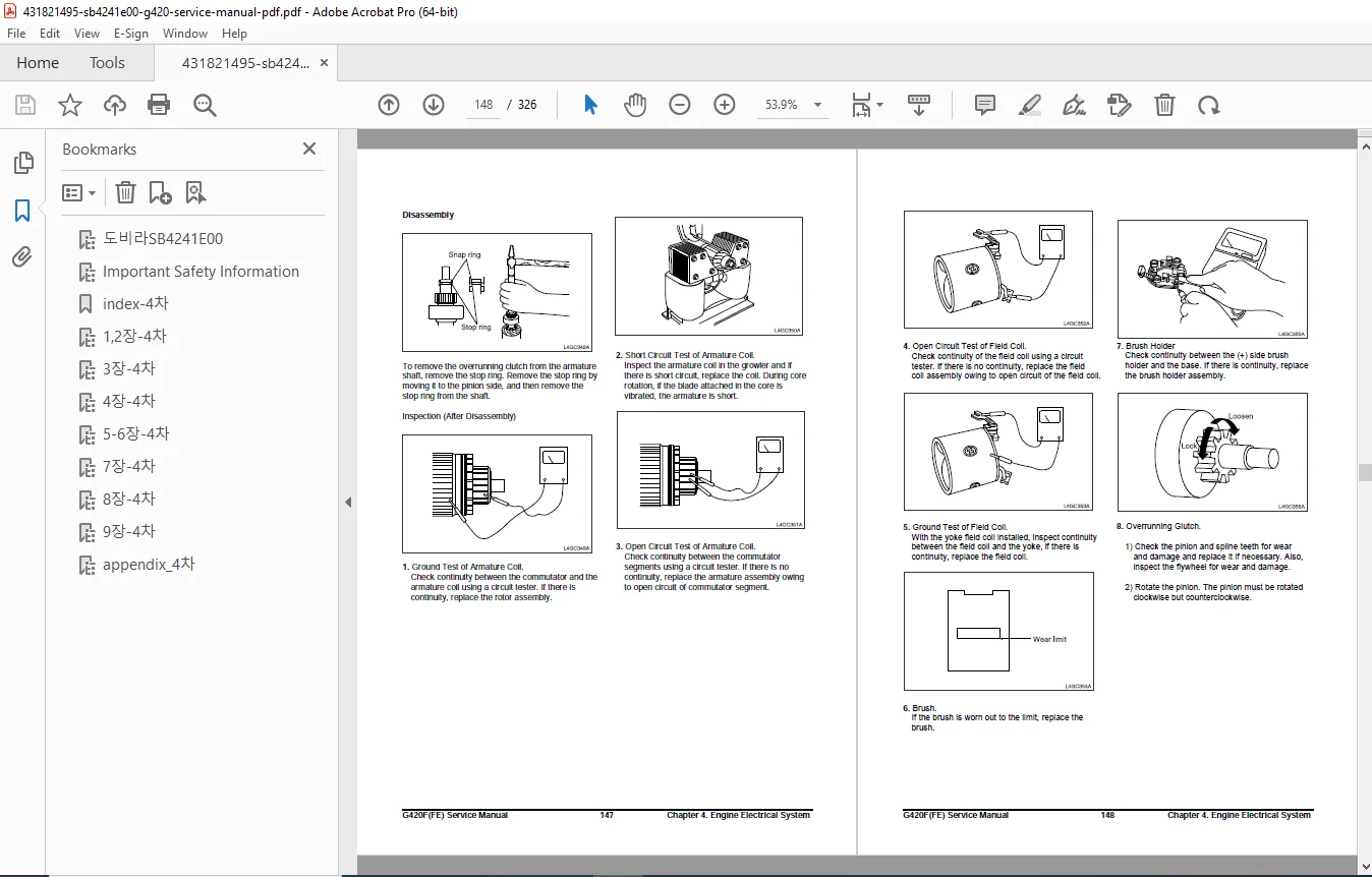
Cylinder Head Assembly:
- Complete disassembly procedures
- Valve train component inspection
- Cylinder head resurfacing specifications
- Valve seat insert service
- Assembly with proper torque sequences
Lubrication System:
- System description and oil flow diagrams
- Testing and adjustment procedures
- Oil pressure specifications: 167 kPa (24 psi) @ low idle
- Oil temperature ranges: 80°C minimum, 125°C maximum, 99-110°C recommended
- Oil pressure switch testing
- Front case and oil pump service
- Oil pump clearance specifications
Camshaft, HLA, Timing Chain:
- Component identification
- Removal procedures with proper timing
- Hydraulic lash adjuster inspection and testing
- Camshaft bearing clearances
- Timing chain wear measurement
Crankshaft Service:
- Main bearing clearance specifications
- Crankshaft runout and wear limits
- Journal diameter measurements
- Thrust bearing clearances
Flywheel and Housing:
- Flywheel runout specifications
- Housing alignment verification
- Bolt torque specifications
Piston and Connecting Rod:
- Piston-to-cylinder clearances
- Ring gap specifications and installation
- Connecting rod bearing clearances
- Piston pin clearances
- Assembly procedures with ring positioning
Cylinder Block:
- Cylinder bore measurement and wear limits
- Deck surface flatness specifications
- Main bearing bore alignment
Chapter 4: Engine Electrical System
Specifications:
- Complete electrical system specifications
- Voltage and resistance values
Ignition System:
- Coil-on-plug (COP) distributorless ignition
- Electronic control by ECM
- Component identification and location
- Ignition timing inspection procedures
- Ignition coil driver (power transistor) testing
- Ignition coil inspection and resistance testing
- Spark plug inspection (platinum type, 0.8mm gap)
- 12V operation, 4 coils system
Charging System:
- General description and operation
- Troubleshooting procedures and flowcharts
- Alternator specifications: 13.5V, 90 amp output
- Disassembly and installation procedures
- Voltage regulator testing
- Stator and rotor testing
Starting System:
- General description
- Diagnosis procedures with test flowcharts
- Start relay testing procedures
- Troubleshooting no-crank conditions
- Starter motor specifications: 12V, 1.7 kW
- Starter removal and installation
Chapter 5: Engine Management System (EMS)
General Information:
- System specifications
- Service standards
- Component location diagrams
G420FE EMS Overview:
- General system description
- Electronic control architecture
- LPG fuel system operation with closed loop control
- MPI gasoline system operation with closed loop control
- Electronic throttle system (drive-by-wire)
- Ignition system control
- Exhaust system with 3-way catalyst
- SECM (Simplified Engine Control Module) functions
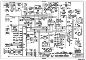
SECM Wiring Diagrams:
- Complete wiring schematics for G420FE
- Connector pin-outs
- Signal flow diagrams
G420F EMS Overview:
- System description for non-EPA version
- LPG fuel system operation with open loop control
- MPI gasoline system operation
- Electronic throttle system
- Ignition system
- Exhaust system without catalyst
- SECM functions
SECM Wiring Diagrams for G420F:
- Complete electrical schematics
- Sensor and actuator connections
EMS Inspection and Repair:
- Engine Control Module (SECM) testing and replacement
- Camshaft position sensor (Hall sensor type)
- Crankshaft position sensor (magnetic inductive type)
- MAP (Manifold Absolute Pressure) sensor testing
- IAT (Intake Air Temperature) sensor verification
- Oxygen sensor testing – Pre-catalyst (gasoline dual fuel system)
- Oxygen sensor testing – Post-catalyst (dual oxygen sensor system)
- ECT (Engine Coolant Temperature) sensor for ECM
- ECT sensor for gauge on instrument panel
- LP fuel temperature sensor
- Accelerator angle sensor (two-output signals in pedal)
- Transmission oil temperature switch
- Ground speed limit switch (optional feature)
- Electronic throttle body with TPS (throttle position sensor)
Chapter 6: LPG Fuel Delivery System
G420FE LP System:
- System removal and installation procedures
- Hose connection routing diagrams
- N-2007 regulator removal and installation (two-stage negative pressure type)
- CA100 mixer removal and installation (diaphragm type air valve, downdraft)
- Testing and adjustment procedures
- N-2007 regulator service testing
- AVV (Air Valve Vacuum) testing procedures
- MI-07 service tool connection
- Idle mixture adjustment with dual dither system
- Fuel trim valve (FTV) dual dither system operation
- Parts description with exploded diagrams
- CA100 mixer component breakdown
- N-2007 regulator specifications
G420F LPG System:
- Removal and installation procedures
- Fuel system connection diagrams
- N-2001 regulator/converter service (two-stage negative pressure)
- CA100 mixer for G420F specifications
- Testing and adjustment procedures
- N-2001 regulator service testing
- AVV testing without FTV
- MI-07 service tool procedures
- Idle mixture adjustment for open loop system
- Parts descriptions and exploded views
Chapter 7: MPI Gasoline Fuel Delivery System
Specifications:
- Fuel pressure: 3.5 bar
- Injector specifications: 12V electric
Special Tools:
- Required tools with part numbers
- Fuel pressure test equipment
Components Location:
- In-tank fuel pump module layout
- Fuel filter and strainer positioning
- Gasoline pressure regulator
- Electric fuel injector locations
Fuel Pressure Test:
- Test procedures and pressure specifications
- Diagnostic procedures for low/high pressure
- Fuel pump performance verification
Fuel Injector:
- Injector removal and installation
- Electrical connector procedures
- O-ring replacement
Injector Inspection:
- Resistance testing
- Spray pattern evaluation
- Flow rate testing
- Cleaning procedures
Fuel Pump:
- In-tank electric fuel pump (12V)
- Removal and installation procedures
- Electrical testing
- Fuel strainer service
Chapter 8: Basic Troubleshooting
Preliminary Checks:
- Before starting inspection checklist
- Visual/physical inspection procedures
- Safety precautions
Basic Troubleshooting Guide:
- Customer problem analysis sheet
- Basic inspection procedure flowcharts
- Connector inspection procedures
- Pin-out diagrams for all connectors
- Continuity and resistance testing
Symptom Troubleshooting Chart:
- Comprehensive symptom-based diagnostic guide
- Probable causes and solutions
Specific Troubleshooting Procedures:
- Intermittents: Detection and diagnosis methods
- Surges and/or Stumbles: Fuel system, ignition, and sensor testing
- Engine Cranking but Will Not Start/Difficult to Start: Fuel delivery, spark, compression checks
- Lack of Power/Slow Response: Fuel pressure, air intake, exhaust restriction testing
- Poor High Speed Performance: Governor settings, fuel delivery, ignition timing
- Hesitation During Acceleration: Throttle body, fuel trim, sensor verification
Key Features & Technical Highlights
✓ EPA 2007 Compliant Documentation – Complete service information for emission-certified engines
✓ Dual Fuel Capability – Service procedures for LP, gasoline, and dual fuel configurations
✓ Electronic Engine Management – Comprehensive EMS diagnostics and repair
✓ Drive-by-Wire System – Electronic throttle body service and calibration
✓ Closed Loop Fuel Control – Advanced fuel trim and oxygen sensor systems
✓ Distributorless Ignition – Coil-on-plug system with electronic control
✓ DOHC 16-Valve Design – Hydraulic lash adjuster service procedures
✓ Timing Belt System – Complete removal, inspection, and installation procedures
✓ Catalytic Converter Service – 3-way catalyst maintenance and testing
✓ MI-07 Service Tool – Diagnostic tool connection and usage procedures
File Details
Manual Name: Doosan G420FE/G420F LP/Dual Fuel Engine Service Manual
Document Number: SB4241E00
Publication Date: April 2007
Manufacturer: Doosan Industrial Vehicle
Models Covered: G15S-5, G18S-5, G20SC-5, GC15S-5, GC18S-5, GC20SC-5, G20E-5, G25E-5, G30E-5, GC20E-5, GC25E-5, GC30E-5, GC33E-5
Total Pages: 326 pages
PDF Quality: High-quality factory manual with searchable text
File Size: 13.7 MB
Format: Fully searchable PDF with diagrams and illustrations