Doosan G424I(E) Engine Service Manual PDF DOWNLOAD
Original price was: $95.00.$28.95Current price is: $28.95.
Download the Doosan G424I(E) LP/Gasoline engine service manual PDF for forklift repair on models G15S-5 to G30E-5. This Doosan forklift engine troubleshooting guide covers specifications, maintenance, mechanical disassembly, electrical systems, and fuel delivery in the G424I engine repair manual. Crucial for technicians handling Doosan G424I schematic diagrams PDF and forklift engine maintenance.
Description
Doosan G424I(E) Engine Service Manual PDF DOWNLOAD
Description
The Doosan G424I(E) Engine Service Manual PDF Download is a thorough guide for servicing LP/Gasoline engines in Doosan forklifts. This Doosan forklift engine troubleshooting guide details general information, maintenance procedures, mechanical systems, electrical components, engine management, LPG and MPI fuel systems, and advanced diagnostics, making it an essential G424I engine repair manual for professional mechanics.
File Details:
- Manual Name: Service Manual G424I(E) LP/Gasoline Engine
- Models Covered: G15S-5, G18S-5, G20SC-5, G20E-5, G25E-5, G30E-5
- Year: 2011
- Manual PDF Quality: High-quality scanned document
- No. of Pages: 274
The manual includes safety precautions, tightening torques, and troubleshooting charts. Below is the neatly categorized Index (Table of Contents) extracted from the manual:
- Chapter 1: General Information
- Precautions before Service (Page 7)
- Tightening Torque (Page 10)
- Recommended Lubricants and Capacities (Page 11)
- Engine Model and Engine Serial Number (Page 12)
- General Specification (Page 13)
- Engine Power and Torque (Page 15)
- Chapter 2: Recommended Maintenance
- General Maintenance (Page 20)
- Test Fuel System for Leaks (Page 20)
- Inspect Engine for Fluid Leaks (Page 20)
- Inspect Vacuum Lines and Fittings (Page 20)
- Inspect Electrical System (Page 20)
- Inspect Foot Pedal Operation (Page 20)
- Engine Oil Classification (Page 21)
- Checking Engine Oil Level (Page 22)
- Replacing Engine Oil and Filter (Page 22)
- Cooling System Maintenance (Page 24)
- Coolant Recommendation (Page 24)
- Check Coolant Level (Page 24)
- Inspect Coolant Hoses (Page 24)
- Checking coolant leaks (Page 25)
- Specific gravity test (Page 25)
- Relation between Coolant concentration and Specific Gravity (Page 25)
- Checking and Adjusting Drive Belt (Page 26)
- Adjusting (Page 27)
- Checking Belt for Damage (Page 27)
- Ignition System Maintenance (Page 28)
- Inspect Battery System (Page 28)
- Inspect Ignition System (Page 28)
- Inspection of Ignition Timing (Page 28)
- Inspection of Spark Plug (Page 29)
- Fuel System Maintenance (Page 31)
- Replace LP Fuel Filter Element (Page 31)
- Testing Fuel Lock-off Operation (Page 32)
- Pressure Regulator/Converter Inspection (Page 32)
- Inspect Air/Fuel Valve Mixer Assembly (Page 33)
- Inspect for Intake Leaks (Page 33)
- Inspect Throttle Assembly (Page 33)
- Checking the TMAP Sensor (Page 33)
- Exhaust System Maintenance (Page 33)
- Inspect Engine for Exhaust Leaks (Page 33)
- Maintenance Schedule (Page 34)
- Chapter 3: Engine Mechanical System
- General Information (Page 36)
- Specifications (Page 36)
- Tightening Torque (Page 39)
- Compression (Page 40)
- Valve Clearance (Page 41)
- Troubleshooting (Page 45)
- Special service tools (Page 48)
- Timing System (Page 49)
- Component (Page 49)
- Removal (Page 51)
- Inspection (Page 53)
- Installation (Page 54)
- Cylinder Head Assembly (Page 59)
- Components (Page 59)
- Removal (Page 60)
- Inspection (Page 62)
- Installation (Page 66)
- Cylinder Block Assembly (Page 70)
- Components (Page 70)
- Disassembly (Page 72)
- Inspection (Page 74)
- Reassembly (Page 81)
- Cooling System (Page 86)
- Components (Page 86)
- Water pump / Thermostat (Page 87)
- Troubleshooting (Page 89)
- Lubrication System (Page 91)
- Component (Page 91)
- Oil pump (Page 92)
- Inspection (Page 93)
- Engine Oil (Page 95)
- Manifold System (Page 96)
- Intake manifold (Page 96)
- Exhaust manifold (Page 99)
- Engine Electrical System (Page 101)
- Specification (Page 101)
- Trouble Shooting (Page 102)
- Ignition System (Page 104)
- Repair procedures (Page 104)
- On-vehicle Inspection (Page 106)
- Emission control system (Page 107)
- Emission (Page 108)
- Fuel System (Page 109)
- Actuators (Page 109)
- Tightening torques (Page 109)
- Troubleshooting (Page 110)
- Chapter 4: Engine Electrical System
- Specifications (Page 116)
- Ignition Coil (Page 116)
- Spark Plug (Page 116)
- Starter Motor (Page 116)
- Alternator (Page 116)
- Ignition System (Page 117)
- Coil-On-Plug Ignition System (Page 117)
- COP Components (Page 117)
- Misfires (Page 118)
- COP Checks (Page 118)
- Inspection of Ignition Timing (Page 120)
- Inspection of Ignition Coil Drivers (Power TR) (Page 120)
- Inspection of Ignition Coil (Page 121)
- Inspection of Spark Plug (Page 122)
- Charging System (Page 124)
- General Description (Page 124)
- Components (Page 125)
- Troubleshooting (Page 126)
- Disassembly and Installation (Page 132)
- Inspection (Page 134)
- Starting System (Page 137)
- Description (Page 137)
- Starter (Page 139)
- Chapter 5: Engine Management System (EMS)
- General Information (Page 146)
- Specifications (Page 146)
- Component Location (Page 152)
- G424iE EMS (Engine Management System)
- Overview (Page 156)
- General Description (Page 156)
- LPG Fuel System Operation (Page 159)
- MPI Gasoline System Operation (Page 166)
- Electronic Throttle System (Page 167)
- Ignition System (Page 168)
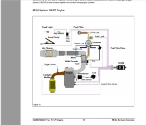
- Exhaust System (Page 169)
- SECM (Page 171)
- SECM Wiring Diagrams for G424iE (Page 174)
- G424i EMS (Engine Management System)
- Overview (Page 176)
- General Description (Page 176)
- LPG Fuel System Operation (Page 179)
- N-2001 Operation (Page 180)
- SECM (Page 183)
- SECM Wiring Diagrams for G424i (Page 184)
- EMS Inspection and Repair (Page 185)
- Engine Control Module (SECM) (Page 185)
- Engine Control System (Page 189)
- Oxygen Sensor (Pre-Catalyst) (Page 191)
- Oxygen Sensor (Post-Catalyst) (Page 192)
- LP Fuel Temperature Sensor (Page 194)
- Angle Sensor-Accelerator (Page 195)
- Transmission Oil Temperature Switch (Page 196)
- Ground Speed Limit Switch (optional) (Page 197)
- Electronic Throttle Body (Page 198)
- Chapter 6: LPG Fuel Delivery System
- G424iE LP System Inspection and Repair (Page 199)
- Removal and Installation (Page 199)
- Tests and Adjustments (Page 204)
- Parts Description (Page 210)
- G424i LP System Inspection and Repair (Page 214)
- Removal and Installation (Page 214)
- Tests and Adjustments (Page 219)
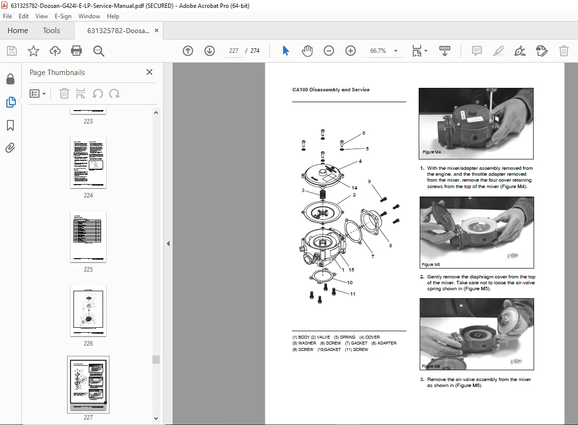
- Parts Description (Page 223)
- Chapter 7: MPI Gasoline Fuel Delivery System
- Specification (Page 232)
- Special Tools (Page 232)
- Components Location (Page 233)
- Fuel Pressure Test (Page 234)
- Release The Internal Pressure (Page 234)
- Install The Special Service Tool (SST) For Measuring The Fuel Pressure (Page 234)
- Inspect Fuel Leakage On Connection (Page 235)
- Fuel Pressure Test (Page 235)
- Release The Internal Pressure (Page 235)
- Remove The Special Service Tool (SST) And Connect the Fuel Line (Page 236)
- Inspect Fuel Leakage On Connection (Page 236)
- Injector (Page 236)
- Component Location (Page 236)
- Description (Page 236)
- Injector Inspection (Page 238)
- Operation check (Page 238)
- Resistance Measurement Between Terminals (Page 238)
- Removal (Page 238)
- Inspection (Page 239)
- Installation (Page 239)
- Fuel Pump (Page 240)
- Removal (Including Fuel Filter And Fuel Pressure Regulator) (Page 240)
- Chapter 8: Basic Troubleshooting
- Preliminary Checks (Page 241)
- Before Starting (Page 241)
- Visual/Physical check (Page 241)
- Basic Troubleshooting Guide (Page 242)
- Customer Problem Analysis Sheet (Page 242)
- Basic Inspection Procedure (Page 243)
- Connector Inspection Procedure (Page 244)
- Symptom Troubleshooting Guide Chart for MPI Gasoline Engine (Page 248)
- Basic Troubleshooting (Page 254)
- Intermittents (Page 254)
- Corrective Action (Page 254)
- Surges and/or Stumbles (Page 255)
- Engine Cranking but Will Not Start / Difficult to Start (Page 256)
- Lack of Power, Slow to Respond / Poor High Speed Performance / Hesitation During Acceleration (Page 258)
- Detonation / Spark Knock (Page 260)
- Backfire (Page 261)
- Dieseling, Run-on (Page 261)
- Rough, Unstable, Incorrect Idle, or Stalling (Page 262)
- Cuts Out, Misses (Page 264)
- Poor Fuel Economy / Excessive Fuel Consumption LPG Exhaust Smell (Page 265)
- High Idle Speed (Page 266)
- Excessive Exhaust Emissions or Odors (Page 267)
- Diagnostic Aids for Rich / Lean Operation (Page 268)
- Chart T-1 Restricted Exhaust System Check (Page 269)
- Chapter 9: Advanced Diagnostics
- Reading Diagnostic Fault Codes (Page 270)
- Displaying Fault Codes (DFC) from SECM Memory (Page 270)
- Clearing Fault (DFC) Codes (Page 270)
- Fault Action Descriptions (Page 271)
- Fault List Definitions (Page 271)
This Doosan G424I schematic diagrams PDF aids in precise forklift engine maintenance with wiring diagrams and parts descriptions. No index beyond the TOC is noted.
Enhance your forklift repairs—download this Doosan G424I(E) service manual PDF now for immediate, expert guidance!