
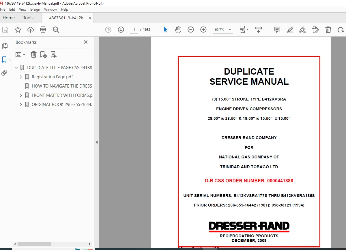
Dresser-Rand B412KVSRA Engine Driven Compressor Service Manual (2009)
Original price was: $120.00.$22.95Current price is: $22.95.
Get the official Dresser-Rand B412KVSRA engine-driven compressor service manual (Dec 2009). Includes essential safety precautions, safety labels, support/service resources, training info, metric conversions, and guidance for navigating the electronic manual using bookmarks/search—ideal for technicians maintaining B412KVSRA units.
Description
Dresser-Rand B412KVSRA Engine Driven Compressor Service Manual (2009) PDF DOWNLOAD
Description
🔧 Manual Overview
This OEM service manual covers Type B412KVSRA engine-driven compressors (15.00″ stroke type), including serial range B412KVSRA177S thru B412KVSRA185S (December 2009 publication). It’s designed for technicians and operators who need safe operating guidance and proper service documentation for the unit.
🧭 What’s Inside (Contents / Sections)
✅ Main Included Sections
Disclaimer / Warning Notice
Safety Precautions
Safety Labels
Sales, Support, Operations Information
Service Centers
Technical Compressor Training
Service Literature Reader Survey
Metric Conversions
🔎 Electronic Manual Navigation (How to Use)
Using Bookmarks + Table of Contents for fast section access
Using the Find/Search tool to quickly locate keywords and topics inside the manual
Table of Contents (from PDF bookmarks)
FRONT MATTER
PG662A – Safety Precautions
PG2914A – Safety Labels
PG2697E – Product Support / Service Centers
PG2551A – Technical Compressor Training
PG2915 – Service Literature Reader Survey
PG732C – Metric Conversion Equivalents
P/L6297A – Flywheel Lock Warning
P/L5933I – Approved Lube Oils List
PG931 – Performance Pages
TX11409A/B/C – Performance Curves
SECTION 1 – ENGINE INSTRUCTIONS
PG840 – KVSR, A Series
PART I – INSTALLATION
General
Storage
Location
Building
Foundation Size & Design
Setting & Leveling Frame
Grouting
Engine Assembly
Compressor End Assembly
Engine & Compressor Piping
Electrical Wiring
PART II – SYSTEMS
General
Starting System – Air/Gas Motor Starting
Starting System – Air to Head Starting
Fuel System
Inlet Air System
Exhaust System
Cooling System
Lubrication System
Ignition System
Starting Controls & Safety Shutdown System
PART III – OPERATION
General
Preparation for Initial Start
Starting Procedures
Break-In Run
Routine Shutdown
Emergency Shutdown
Shutdown for an Extended Period
Routine Operation & Maintenance
Trouble Shooting
H36792G – Starting Motor & Piping
PART IV – MAINTENANCE
General
Safety Precautions
Initial Adjustments
Frame & Frame Top
Crankshaft
Flywheel
Crankshaft Oil Seal
Main Bearings
Power Cylinder Head
Valves & Valve Gear
Hydraulic Valve Lifters
Mechanical Valve Lifters
Valve Tappets & Push Rods
Camshaft & Cam Box
Accessory Drives
Water Pumps
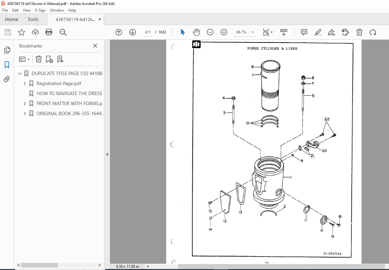
Power Cylinders & Liners
Power Pistons & Rings
Power Connecting Rods & Bearings
Compressor Connecting Rods & Bearings
Compressor Crossheads
Balance Weight Cylinders – Size B412 Units
PART V – GENERAL DATA
KVSR Engine Specifications
Operating Data
Power End Weights
Part Fits & Tolerances
Tightening Requirements
SECTION 2 – COMPRESSOR END INSTRUCTIONS
PG738 – TFE Compressor Piston Rings
General
Special Operating & Handling Instructions
Establishing Ring Wear Rate
Ring Replacement or Adjustment
Installing One-Piece Piston Rings & Split Riders
Installing Two & Three Piece Piston Rings
Breaking in New Piston & Rider Rings
Piston & Ring Clearances (US)
Piston & Ring Clearances (Metric)
PG738 Add B – Lubricated TFE Piston & Rider Rings
PG641 – Warning Valve Locations
PG628C – Compressor Cylinders
General
Cylinder Nameplate Data
Compressor Piping
Recommendations for Installation/Fabrication/Testing/Cleaning of Air or Gas Piping
Temporary Line Filters
Starting Loading Bypass Piping
Water Piping
Safety Valves
Intercooler, Aftercooler & Receiver
Cylinder Installation
Completing Cylinder Assembly
Adjusting Piston End Clearance
Adjusting Piston Rod Runout
Cylinder Lubrication System
Cylinder Cooling System
Water Cooled Cylinders
Static Cooled Cylinders
Thermo-Syphon Cooling
Water Cooled Packing
Regulation
Break-In & Operation – Lubricated Cylinders
Break-In & Operation – Mini Lube Cylinders
Break-In & Operation – Non-Lube Cylinders
Extended Shutdown
Lubricated Cylinders
Non-Lubricated Cylinders
Routine Maintenance
Operator’s Hourly Routine
Every Eight Hours
Semi-Annual
Annual
Periodic
Maintenance Hints
Cleaning the Cylinders
Locating Cylinder Leakage
Trouble Shooting
Cylinder Maintenance
Safety Precautions
Cylinder Disassembly
Outer Head Removal
Disassembly & Assembly of Pistons & Piston Rods
Reapplication of Babbitt Sprayed Rider Bands
Reclamation of Piston Rods
Compressor Piston Rings
Piston Rod Pressure Packing
Assembly Clearances
Compressor Cylinder Bolting
PG631A – Compressor Cylinder Lubrication
General
Break-In Considerations
Lubricating Oil Recommendations
General Requirements
Service Considerations
Lube Recommendations for Ammonia Refrigeration Compressor Cylinders
Inspection
Synthetic Lubricants
Piston Rod Packing Lubrication
Cylinder Lubricator
PG652 – General Instructions for Compressor Valves
Introduction
General Recommendations
Valve Maintenance
Troubleshooting
PG454A – Importance of Maintaining Valve Records
How Does a Valve Operate
What Causes Valve Failure & Remedies
How Valve Records Help (Case Histories)
Typical Valve Record Systems
For Best Valve Life
PG773 – Type A Channel Valves (Lubricated)
General
Description of Operation
Valve Maintenance Recommendations
To Disassemble & Service Valve
To Reassemble Valve
PG771 – Reconditioning Data for Type A Channel Valves
PG825 – UL47 Outside Operated Clearance Valve
General
Control & Vent Piping
SECTION 3 – PARTS LIST
Parts Index
PG557K – How to Order Replacement Parts
PG707B – Reporting Service Part Defects
Tab “A” – Frame Parts
Tab “B” – 28.50″ Compressor Cylinder
Tab “C” – 18.00″ Compressor Cylinder
Tab “D” – 10.50″ Compressor Cylinder
SECTION 4 – ACCESSORY LITERATURE
Accessory Literature Index
Tab “A” – Ignition System
Tab “B” – Governor
Tab “C” – Lubrication System
Tab “D” – Control & Shutdown System
Tab “E” – Miscellaneous
Tab “F” – Control Panel
SECTION 5 – DRAWINGS
Drawing Index
Post Cooling Schematic (R82000)
Engine Control Schematic (F26482AW)
Shutdown Schematic (R58391K)
Lube Oil System (W134751A)
Lubrication System (R51482LL)
Lubricating Oil Piping Schematic (R50055AC)
Header to MB Pipe Arrangement (R57955A)
Power Valve Stem Lubrication (W102736P3)
Compressor Cylinder Lube Schematic (H39586P17)
Woodward PG Governor Linkage Setting (R37411)
Fuel Gas Piping Details (R47972Y)
Altronic II Ignition Wiring Diagram (R51349D)
Timing Light Adapter Schematic (W124319)
Pneumatic Schematic (H31984H)
Cooling Water System BOM (W95554AZ)
Cooling System (R41897CN)
Space Required to Remove Power Piston & Rod (W31380F)
Compressor Balance Weight P/L (6804)
Balance Weight Record (W88236)
Critical Speed Blank-Out Circuit (R44569C)
General Plan (L9642)
Foundation Plan (L9643)
⚠️ Safety Emphasis (Important)
The manual stresses reading and understanding all safety instructions before installation, operation, or service. It also explains the safety signal words used throughout the document (DANGER / WARNING / CAUTION / NOTE) so you can recognize risk levels instantly.
📄 File Details
| Item | Details |
|---|---|
| Manual Name | Dresser-Rand Type B412KVSRA Service Manual |
| Models Covered | B412KVSRA engine-driven compressors (15.00″ stroke type) |
| Year | 2009 (December) |
| PDF Quality | Searchable PDF (digital text) |
| Pages | 1633pages |
Stop guessing and service your compressor with the correct OEM documentation—download this manual now and keep the right safety and service guidance at your fingertips for faster, safer maintenance.