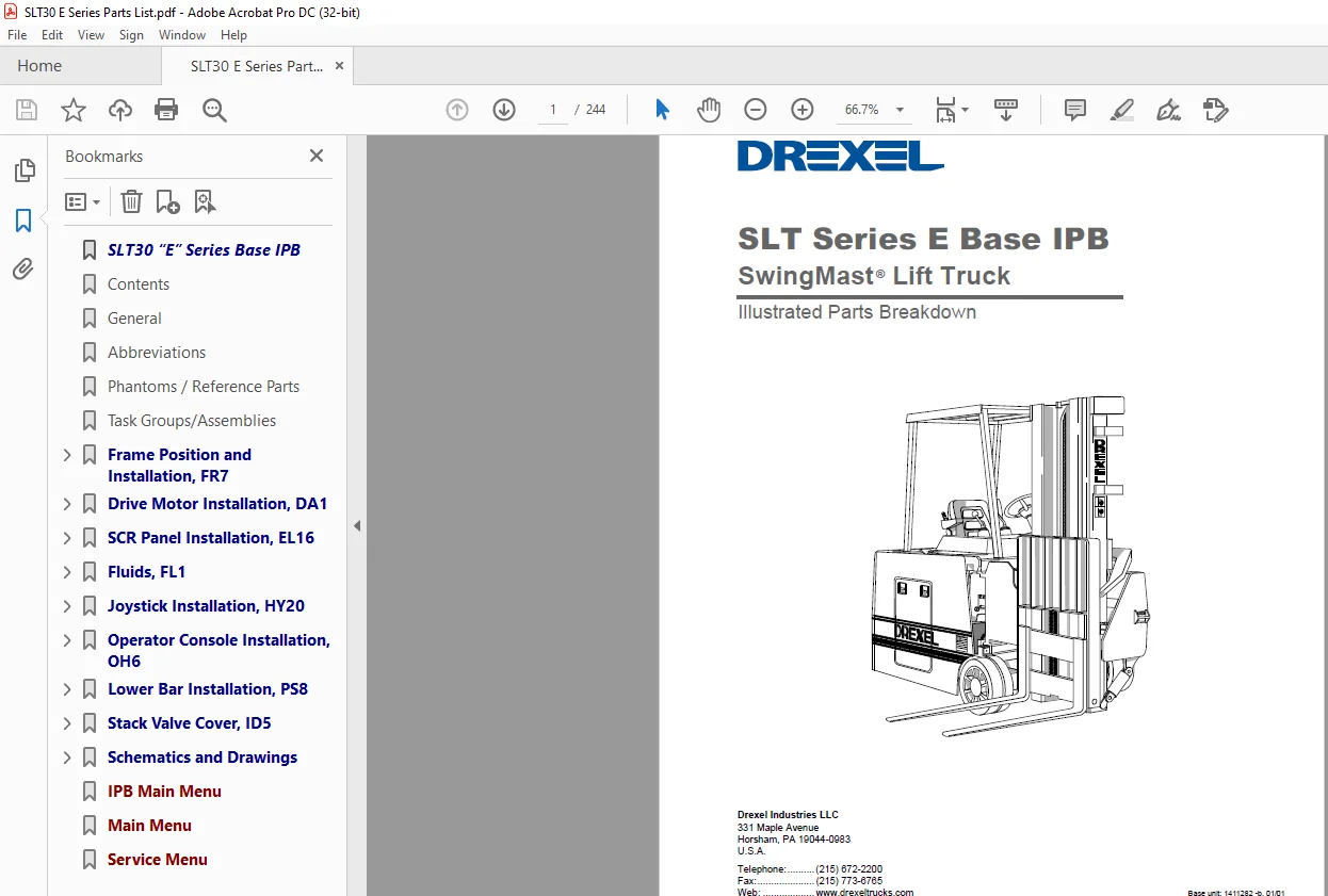
Drexel SLT Series E Base IPB SwingMast Lift Truck Illustrated Parts Breakdown Manual PDF
$18.95
Drexel SLT Series E Base IPB SwingMast Lift Truck Illustrated Parts Breakdown Manual – PDF DOWNLOAD
Description
Drexel SLT Series E Base IPB SwingMast Lift Truck Illustrated Parts Breakdown Manual – PDF DOWNLOAD
FILE DETAILS:
Drexel SLT Series E Base IPB SwingMast Lift Truck Illustrated Parts Breakdown Manual – PDF DOWNLOAD
Language :English
Pages :244
Downloadable : Yes
File Type : PDF
IMAGES PREVIEW OF THE MANUAL:
DESCRIPTION:
Drexel SLT Series E Base IPB SwingMast Lift Truck Illustrated Parts Breakdown Manual – PDF DOWNLOAD
General
This section contains an illustrated parts breakdown (list) and drawings for the serviceable assemblies and components
of the Standard SLT30 “E” Series SwingMast lift trucks.
Abbreviations
The following abbreviations may be used in this Options
IPB:
#n ………….the measurement of an inner diameter in
32nds of an inch; example, #10 hose is has
an inner diameter of 10/32” or 5/16”.
A/R ………..As required
Barb……….Barbed, a tapered hose nipple with ridges or
“barbs” which keep the hose from slipping off.
Cl…………..Class, used to specify yield strength of metric
fasteners.
Cm…………centimeters
Ext …………External
Frk …………Fork, pronged electrical connector
Fwd ……….Forward
Ga …………Gauge
Grd, Gr …..Grade – when hardware lists a grade rating, it
is important to maintain that rating when
replacing parts.
HS …………Hardened steel
Hex………..Hexagonal
ID, ID ……..Inner diameter or “identification” (tag or plate).
IPB ………..Illustrated Parts Breakdown
JIC…………Joint Industrial Conference, an industry standard
used to describe a fitting.
Lh, LH…….Left hand
mm ………..millimeters
Mn …………Metric measurement; example, M8, M10,
etc.). The number indicates the nominal diameter
in millimeters
Mtg ………..Mounting
n/s …………Parts that are not shown but serviceable.
No………….Number
Nom……….Nominal, i.e., suitable for nearest practical
dimension. For example, a washer suitable
for a 5/16” screw has an inner diameter
greater than 5/16”, but its nominal dimension
is 5/16.”
NPT ……….National pipe thread
NPTF……..National pipe thread fine
NSS……….Not supplied separately (example, assemblies
or collection of parts which cannot be purchased
separately).
OAL ……….Overall length, usually the stretched-out
length of a hose or cable (including fittings), or
the height of an unextended mast.
OD, Od …..Outer diameter
ORB ………O-ring boss, usually on a fitting, a threaded
end equipped with a groove or lip to hold an
O-ring.
p/n …………Part number
REC……….Schematic designator for an SCR (example, 4
REC.)
Rev………..Reverse
Rh, RH …..Right hand
SCR……….Silicon controlled rectifier
Str………….Straight, usually to describe a hydraulic fitting
(vs. elbow)
Term ………Terminal, electrical
w/…………..with
w/out………without
Phantoms / Reference Parts
Quantities for some parts may be labeled “Pht” (phantom) or “Ref” (reference). A phantom is an assembly which does not exist as a separate unit. A reference item is not officially part of the parent assembly, but is shown on the illustration to make it easier to locate and identify. A zero quantity may also be used to identify a reference item.
Task Groups/Assemblies
Task groups and/or assemblies are identified by a twocharacter
letter code and a number suffix, example,
OH389 or ET351. The letter codes are as follows:
CO…………Covers
CT …………Counterweights
DA …………Drive Axle and Wheels
EL………….Electrical System
FL………….Fluids and Lubricants
FR …………Frame
HY …………Hydraulic System
IA…………..Inspection and Adjustments
ID…………..Identification, Decals and Paint
LW…………Load Wheels
MA…………Mast
OH…………Overhead Guard, Instrument Panel, Controls
OP…………Options (example, Fork Installation)
PB …………Parking Brake
PS …………Pivot and Shift System
SB …………Service Brake
ST………….Seat
Items not manufactured by Drexel Industries, as well as
some Drexel subassemblies, are identified by assembly
part numbers (p/n:). These items are located immediately
after to the task groups in which they are used.
TABLE OF CONTENTS:
Drexel SLT Series E Base IPB SwingMast Lift Truck Illustrated Parts Breakdown Manual – PDF DOWNLOAD
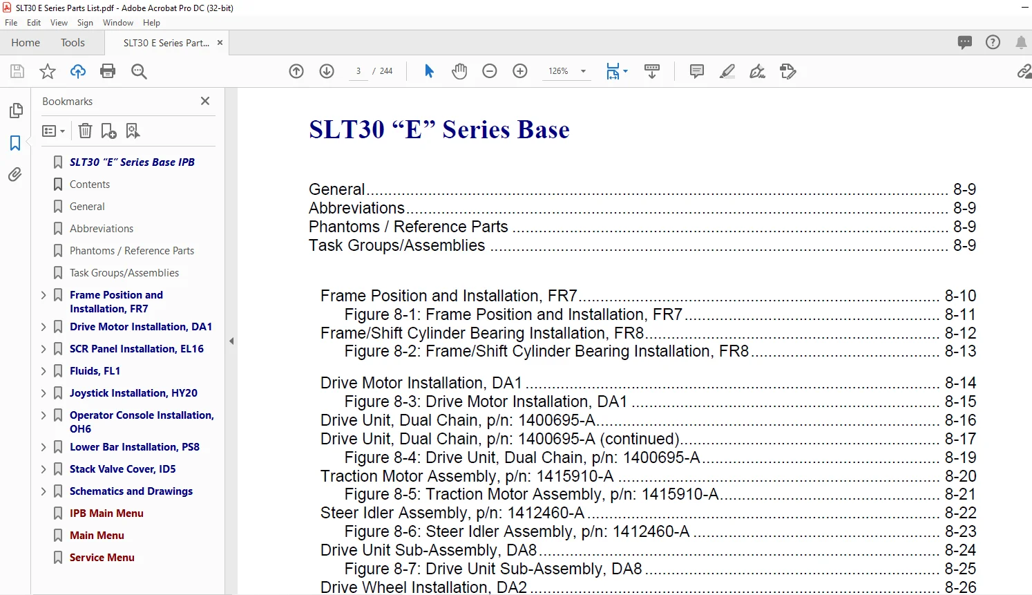
General 8-9
Abbreviations 8-9
Phantoms / Reference Parts 8-9
Task Groups/Assemblies 8-9
Frame Position and Installation, FR7 8-10
Figure 8-1: Frame Position and Installation, FR7 8-11
Frame/Shift Cylinder Bearing Installation, FR8 8-12
Figure 8-2: Frame/Shift Cylinder Bearing Installation, FR8 8-13
Drive Motor Installation, DA1 8-14
Figure 8-3: Drive Motor Installation, DA1 8-15
Drive Unit, Dual Chain, p/n: 1400695-A 8-16
Drive Unit, Dual Chain, p/n: 1400695-A (continued) 8-17
Figure 8-4: Drive Unit, Dual Chain, p/n: 1400695-A 8-19
Traction Motor Assembly, p/n: 1415910-A 8-20
Figure 8-5: Traction Motor Assembly, p/n: 1415910-A 8-21
Steer Idler Assembly, p/n: 1412460-A 8-22
Figure 8-6: Steer Idler Assembly, p/n: 1412460-A 8-23
Drive Unit Sub-Assembly, DA8 8-24
Figure 8-7: Drive Unit Sub-Assembly, DA8 8-25
Drive Wheel Installation, DA2 8-26
Figure 8-8: Drive Wheel Installation, DA2 8-27
Chain Assembly for Steering, p/n: 1400109-B 8-28
Figure 8-9: Chain Assembly for Steering, p/n: 1400109-B 8-29
Steer Idler Installation, DA9 8-30
Figure 8-10: Steer Idler Installation, DA9 8-31
Lower Drive Unit Installation, DA11 8-32
Figure 8-11: Lower Drive Unit Installation, DA11 8-33
Press Drive Plate Studs, DA14 8-34
Figure 8-12: Press Drive Plate Studs, DA14 8-35
Spindle Installation, LW3 8-36
Figure 8-13: Spindle Installation, LW3 8-37
Load Wheel Installation, LW6 8-38
Figure 8-14: Load Wheel Installation, LW6 8-39
Load Wheel Sub-Assembly, LW7 8-40
Figure 8-15: Wheel Sub-Assembly, LW7 8-41
Service Brake Installation, SB5 8-42
Figure 8-16: Service Brake Installation, SB5 8-43
Table of Contents ❑
SLT30 “E Series,” Base unit, p/n: 1411282 -c, 01/01 8-4
IPB Contents – continued Page
Right and Left Brake Assembly, p/n: 51082-01 and -02 8-44
Figure 8-17: Right and Left Brake Assembly, p/n: 51802 -01 and -02 8-45
SCR Panel Installation, EL16 8-46
Figure 8-18: SCR Panel Installation, EL16 (sheet 1 of 2) 8-47
Figure 8-19: SCR Panel Installation, EL16 (sheet 2 of 2) 8-48
Contactor Panel without Box, p/n: 1405740-A 8-49
Contactor Panel Assembly, p/n: 1405740-A 8-50
Figure 8-20: Contactor Panel Assembly, p/n: 1405740-A 8-51
Contactor, 150A, DPDT, p/n: 1401978-A 8-52
Figure 8-21: Contactor for FR 150A DPDT, p/n: 1401978-A 8-53
Contactor, 300A, SPNO, p/n: 1401979-A 8-54
Figure 8-22: Contactor, 300A, SPNO, p/n: 1401979-A 8-55
Contactor, 100A, SPNO, p/n: 1411980-A 8-56
Contactor, 300A, 36VDC, p/n: 28889-D 8-57
LX SCR Control Panel, p/n: 52511-A 8-58
Figure 8-23: LX SCR Control Panel, p/n: 52511-A 8-59
Battery Connector Sub-Assembly, EL17 8-60
Figure 8-24: Battery Connector Sub-Assembly, EL17 8-61
Wire Harness Installation, EL18 8-62
Figure 8-25: Wire Harness Installation, EL18 8-63
Cable Installation, EL19 8-64
Figure 8-26: Cable Installation, EL19 8-65
Ground Straps Installation, p/n: EL38-A 8-67
Figure 8-27: Ground Straps Installation, p/n: EL38-A 8-67
Fluids, FL1 8-68
Figure 8-28: Fluids, FL1 8-69
Pump Speed Control Installation, HY1 8-70
Figure 8-29: Pump Speed Control Installation, HY1 8-71
Capacitor and Pump Assembly, p/n: 1411418-B 8-72
Figure 8-30: Capacitor and Pump Assembly, p/n: 1411418-B 8-73
Hydraulic Pump and Motor Installation, HY16-B 8-74
Figure 8-31: Hydraulic Pump and Motor Installation, HY16 8-75
Hydraulic Pump and Motor Assembly, p/n: 1411872-C 8-76
Main Pump Seal Kits, p/n: 1402551-B 8-76
Figure 8-32: Hydraulic Pump and Motor Assembly, p/n: 1411872-C 8-77
Main Motor Assembly, p/n: 1400268-A 8-78
Figure 8-33: Main Motor Assembly, p/n: 1404414-A 8-79
Hydraulic Tank Installation, HY6 8-80
Figure 8-34: Hydraulic Tank Installation, HY6 8-81
Table of Contents ❑
SLT30 “E Series,” Base unit, p/n: 1411282 -c, 01/01 8-5
IPB Contents – continued Page
Hydraulic Tank Sub-Assembly, HY13 8-82
Figure 8-35: Hydraulic Tank Sub-Assembly, HY13 8-83
Oil Filter Assembly, p/n: 1412142-A 8-85
Figure 8-36: Oil Filter Assembly, p/n: 1412142-A 8-85
Hydraulic Hose Installation, HY23 8-86
Figure 8-37: Hydraulic Hose Installation, HY23 8-87
Side Shift Hose, HY7 8-89
Figure 8-38: Side Shift Hose, HY7 8-89
Umbilical Assembly Installation, HY8 8-90
Figure 8-39: Umbilical Assembly Installation, HY8 8-91
Umbilical Tray Installation, HY22 8-92
Figure 8-40: Umbilical Tray Installation, HY22 8-93
Umbilical Hoses Connect, HY46 8-94
Figure 8-41: Umbilical Hoses Connect, HY46 8-95
Manifold Assembly, p/n: 1413172-C 8-96
Figure 8-42: Manifold Assembly, p/n: 1413172-C 8-97
Pivot and Tilt Hose Installation, HY19 8-98
Figure 8-43: Pivot and Tilt Hose Installation, HY19 8-99
Orbitrol Tank Hose Installation, HY48 8-100
Figure 8-44: Orbitrol Tank Hose Installation, HY48 8-101
Steer Pump/Motor Installation, HY11 8-102
Figure 8-45: Steer Pump/Motor Installation, HY11 8-103
Pump and Motor Assembly, Steering, p/n: 1413444-A 8-104
Figure 8-46: Pump and Motor Assembly, Steering, p/n: 1413444-A 8-105
Steer Pump/Motor Sub-Assembly, HY12 8-106
Figure 8-47: Steer Pump/Motor Sub-Assembly, HY12 8-106
Steering Pump, p/n: 51734 8-107
Figure 8-48: Steering Pump, p/n: 51734 8-107
Steering Motor Assembly, p/n: 51735 8-108
Figure 8-49: Steering Motor Assembly, p/n: 51735 8-109
Power Steering Hydraulic Installation, HY14 8-110
Figure 8-50: Power Steering Hydraulic Installation, HY14 8-111
Steer Motor Sub-Assembly, HY21 8-112
Figure 8-51: Steer Motor Sub-Assembly, HY21 8-113
Steering Motor Assembly, p/n: 25950 8-114
Figure 8-52: Steering Motor Assembly, p/n: 25950 8-115
Control Valve Installation, HY15 8-116
Figure 8-53: Control Valve Installation, HY15 8-117
Hydraulic Spool Valve Assembly, p/n: 1411868-E 8-118
Figure 8-54: Hydraulic Spool Valve Assembly, p/n: 1411868-E 8-119
Table of Contents ❑
SLT30 “E Series,” Base unit, p/n: 1411282 -c, 01/01 8-6
IPB Contents – continued Page
Control Valve Assembly Breakdown, p/n: 1413566-A 8-120
Control Valve Breakdown, p/n: 1413566-A (continued) 8-121
Figure 8-55: Control Valve Assembly Breakdown, p/n: 1413566-A (sheet 1 of 2) 8-122
Figure 8-56: Control Valve Assembly Breakdown, p/n: 1413566-A (sheet 2 of 2) 8-123
Joystick Installation, HY20 8-124
Figure 8-57: Joystick Installation, HY20 8-125
Joystick Hydraulic Sub-Assembly, HY24 8-126
Figure 8-58: Joystick Hydraulic Sub-Assembly, HY24 8-127
Joystick Assembly, p/n: 1406119-A and 1406120-A 8-128
Figure 8-59: Joystick Assembly 8-129
Instruments and Side Console Installation, ID3 8-130
Figure 8-60: Instruments and Side Console Installation, ID3 8-131
Instrument Panel Assembly, p/n: 1413057-D 8-132
Figure 8-61: Instrument Panel Assembly, p/n: 1413057-D 8-133
Cover Plate Assembly, Standard, p/n: 1401930-C 8-134
Figure 8-62: Cover Plate Assembly, Standard, p/n: 1401930-C 8-135
Side Console Installation, OH7 8-136
Figure 8-63: Side Console Installation, OH7 8-137
Console Cover Sub-Assembly, OH9 8-138
Figure 8-64: Console Cover Sub-Assembly, OH9 8-139
Steering Wheel Installation, ID4 8-140
Figure 8-65: Steering Wheel Installation, ID4 8-141
Horn Button Installation, OH2 8-142
Figure 8-66: Horn Button Installation, OH2 8-143
Operator Console Installation, OH6 8-144
Figure 8-67: Operator Console Installation, OH6 8-145
Steering Column Installation, HY5 8-146
Figure 8-68: Steer Column Installation, HY5 8-147
Steering Column Assembly, p/n: 1400968-D 8-148
Figure 8-69: Steering Column Assembly, p/n: 1400968-D 8-149
Steering Control Assembly, p/n: 25975-C 8-150
Figure 8-70: Steering Control Assembly, p/n: 25975-C 8-151
Key Switch Installation, EL14 8-152
Figure 8-71: Key Switch Installation, EL14 8-153
Key Switch Assembly, p/n: 1404722-C 8-154
Figure 8-72: Key Switch Assembly, p/n: 1404722-C 8-155
Brake Weldment Assembly, SB2 8-156
Figure 8-73: Brake Weldment Assembly, SB2 8-157
Brake Pedal Installation, SB3 8-158
Figure 8-74: Brake Pedal Installation, SB3 8-159
Table of Contents ❑
SLT30 “E Series,” Base unit, p/n: 1411282 -c, 01/01 8-7
IPB Contents – continued Page
Master Cylinder Installation, SB4 8-160
Figure 8-75: Master Cylinder Installation, SB4 8-161
Master Cylinder Assembly, p/n: 1402557-C 8-162
Figure 8-76: Master Cylinder Assembly, p/n: 1402557-C 8-163
Accelerator Unit Installation, EL15 8-164
Figure 8-77: Accelerator Unit Installation, EL15 8-165
Parking Brake Installation, PB17 8-166
Figure 8-78: Parking Brake Installation, PB17 8-167
Parking Brake Sub-Assembly, PB1 8-168
Figure 8-79: Parking Brake Sub-Assembly, PB1 8-169
Equalizer Installation, PB2 8-170
Figure 8-80: Equalizer Installation, PB2 8-171
Brake Cable Installation, PB3 8-172
Figure 8-81: Brake Cable Installation, PB3 8-173
Brake Cable, 113” OAL, p/n: 1400532-A 8-174
Brake Cable, 135” OAL, p/n: 1400533-A 8-174
Figure 8-82: Brake Cable Assembly 8-175
Seat Belt Installation, ST1 8-176
Figure 8-83: Seat Belt Installation, ST1 8-177
Seat Installation, ST2 8-178
Figure 8-84: Seat Installation, ST2 8-179
Driver’s Seat Assembly, p/n: 1410317-D 8-180
Figure 8-85: Driver’s Seat Assembly, p/n: 1410317-D 8-181
Lower Bar Installation, PS8 8-182
Figure 8-86: Lower Bar Installation, PS8 8-183
Lower Bar Sub-Assembly, PS7 8-184
Figure 8-87: Lower Bar Sub-Assembly, PS7 8-185
Pivot and Shift Installation, PS10 8-186
Figure 8-88: Pivot and Shift Installation, PS10 8-187
Pivot and Shift Chain Anchor Installation, PS20 8-188
Figure 8-89: Pivot and Shift Chain Anchor Installation, PS20 8-189
Shift Cylinder Installation, PS6 8-190
Figure 8-90: Shift Cylinder Installation, PS6 8-191
Shift Cylinder Sub-Assembly, PS9 8-192
Figure 8-91: Shift Cylinder Sub-Assembly, PS9 8-193
Shift Cylinder Breakdown, p/n: 1412889-A 8-194
Figure 8-92: Shift Cylinder Breakdown, p/n: 1412889-A 8-195
Side Shift Chains Installation, PS5 8-196
Figure 8-93: Side Shift Chains Installation, PS5 8-197
Cross Head Bearings Installation, PS1 8-198
Figure 8-94: Cross Head Bearings Installation, PS1 8-199
Table of Contents ❑
SLT30 “E Series,” Base unit, p/n: 1411282 -c, 01/01 8-8
IPB Contents – continued Page
Pivot Arm Installation, PS2 8-200
Figure 8-95: Pivot Arm Installation, PS2 8-201
Pivot Stop Pad Installation, PS3 8-202
Figure 8-96: Pivot Stop Pad Installation, PS3 8-203
Pivot Cylinder Installation, PS4 8-204
Figure 8-97: Pivot Cylinder Installation, PS4 8-205
Pivot Cylinder Assembly, p/n; 1400601-A 8-206
Figure 8-98: Pivot Cylinder Assembly, p/n; 1400601-A 8-207
Tilt Cylinder Installation, MA52 8-208
Figure 8-99: Tile Cylinder Installation, MA52 8-209
Tilt Cylinder Assembly, p/n: 1401224-A 8-210
Figure 8-100: Tilt Cylinder Assembly, p/n: 1401224-A 8-211
Stack Valve Cover, ID5 8-212
Figure 8-101: Stack Valve Cover, ID5 8-213
Rear Compartment Seal, ID8 8-214
Figure 8-102: Rear Compartment Seal, ID8 8-215
Battery Door Installation, OH4 8-216
Figure 8-103: Battery Door Installation, OH4 8-217
Battery Door Sub-Assembly, OH8 8-218
Figure 8-104: Battery Door Sub-Assembly, OH8 8-219
Side Cover Weldment Installation, ID9 8-220
Figure 8-105: Side Cover Weldment Installation, ID9 8-221
Rear Compartment Cover, C01 8-222
Figure 8-106: Rear Compartment Covers, CO1 8-223
Floor Plate Installation, OH3 8-224
Figure 8-107: Floor Plate Installation, OH3 8-225
Floor Plate Sub-Assembly, C02 8-226
Figure 8-108: Floor Plate Sub-Assembly, CO2 8-227
Mast Level Indicator Installation, MA2 8-228
Figure 8-109: Mast Level Indicator Installation, MA2 8-229
Overhead Guard Installation, OH1 8-230
Figure 8-110: Overhead Guard Installation, OH1 8-231
Identification Labeling, ID1-C (Serial # 1530 and before) 8-232
Figure 8-111: Identification Labeling, ID1-C (Serial # 1530 and before) 8-233
Figure 8-112: Identification Labeling, ID1-C (Serial # 1530 and before) 8-235
Identification Labeling, ID1 (Serial # 1531 and future) 8-236
Figure 8-113: Identification Labeling, ID1 (Serial # 1531 and future) 8-237
Figure 8-114: Identification Labeling, ID1 (Serial # 1531 and future) 8-239
Schematics and Drawings 8-240
Figure 8-115: Schematics and Drawings (sheet 1 of 2) 8-241
Figure 8-116: Schematics and Drawings (sheet 2 of 2) 8-243
S.M 23/12/24