DYNAPAC Cold Planer PL 1000 RS Operation & Maintenance Manual PDF DOWNLOAD
$27.95
DYNAPAC Cold Planer PL 1000 RS Operation & Maintenance Manual PDF DOWNLOAD
Description
DYNAPAC Cold Planer PL 1000 RS Operation & Maintenance Manual PDF DOWNLOAD
FILE DETAILS:
DYNAPAC Cold Planer PL 1000 RS Operation & Maintenance Manual PDF DOWNLOAD
Language : English
Pages :222
Downloadable : Yes
File Type : PDF
IMAGES PREVIEW OF THE MANUAL:
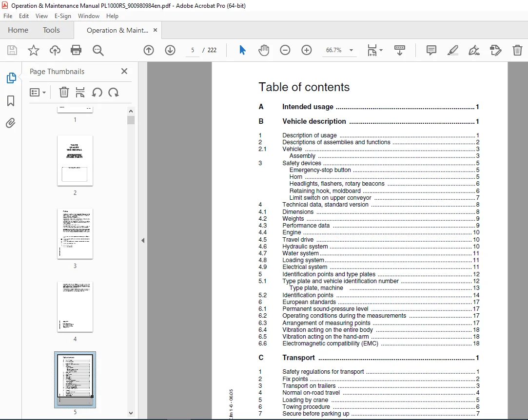
TABLE OF CONTENTS:
DYNAPAC Cold Planer PL 1000 RS Operation & Maintenance Manual PDF DOWNLOAD
A Intended usage 1
B Vehicle description 1
1 Description of usage 1
2 Descriptions of assemblies and functions 2
21 Vehicle 3
Assembly 3
3 Safety devices 5
Emergency-stop button 5
Horn 5
Headlights, flashers, rotary beacons 6
Retaining hook, moldboard 6
Limit switch on upper conveyor 7
4 Technical data, standard version 8
41 Dimensions 8
42 Weights 9
43 Performance data 9
44 Engine 10
45 Travel drive 10
46 Hydraulic system 10
47 Water system 11
48 Loading system11
49 Electrical system 11
5 Identification points and type plates 12
51 Type plate and vehicle identification number 12
Type plate, machine 13
52 Identification points 14
6 European standards 17
61 Permanent sound-pressure level 17
62 Operating conditions during the measurements 17
63 Arrangement of measuring points 17
64 Vibration acting on the entire body 18
65 Vibration acting on the hand-arm 18
66 Electromagnetic compatibility (EMC) 18
C Transport 1
1 Safety regulations for transport 1
2 Fix points 2
3 Transport on trailers 3
4 Normal on-road travel 4
5 Loading by crane 5
6 Towing procedure 6
7 Secure before parking up 7
2
PL1000RS_GBIVZfm 2-6 – 0605
D Operation 1
1 Safety regulations 1
2 Controls 2
21 Control panel 2
3 Other controls 26
31 Controls at operator’s control station 26
Driver’s seat 26
Weather protecting sun roof 27
Side roof 27
Weather-protecting sun roof, hydraulic (O) 28
Battery’s main switch 29
Batteries 29
Milling depth display 30
Swivel-mounted chassis leg 31
Swivel-mounted chassis leg, hydraulic (o) 31
Retaining hook, moldboard 32
Water scales / inclination indicator 33
Throttle valve, levelling unit 34
Load relief of moldboard 34
Direction of travel indicator 35
Working lights / rotary beacons 36
Non-return valves for water spraying / drain valve on water tank 37
Setting valve for water pressure (water spraying) 38
Steps up to water tank 38
Chocks 39
Vandalism protection 40
4 Levelling unit 41
41 MOBA-matic type 41
5 Operating the MOBA-matic 42
6 Operating the MOBA-matic 44
61 Liquid crystal display (1) 48
Activation message 48
Sensor message 49
Changeover between height sensor and lateral slope 49
LED display 50
62 Actual value indicator (O) 51
Connection: 53
Connection of MOBA-matic, actual value indicator and sensors 55
Button usage and possible button combinations on the digital
controller during milling 57
automatic mode – “AUTO” function lamp on 57
63 Basic settings 60
64 Calibration to zero 61
Initial situation for calibration to zero 61
Other tasks 61
Calibration to zero for cable tension and Digi-Sonic sensors
when sensing the ground via the side boards 62
3
PL1000RS_GBIVZfm 3-6 – 0605
65 Actual value calibration 63
Digi-Slope sensor (lateral slope sensor) 63
Initial situation for actual value calibration 63
Other tasks 63
Height sensors (to correct the actual value to the value displayed) 65
7 Operation 66
71 Preparing for operation 66
Devices and aids 66
Before starting work 66
Checklist for machine operator 67
72 Starting the machine 69
Auxiliary starting (electrical starting aid) 71
71
Allowing engine to “warm up” 72
Driving the machine 73
8 Milling instructions 74
“Driving” position 74
“Milling” position 74
Zero setting 75
Surface milling 75
Planing on road surface wheel or on offsets 76
Milling at the curb (with deployed chassis leg) 76
Milling at the curb (with chassis leg swivelled in) 77
Planing without automatic levelling device 79
81 Operating the Moba-matic during milling 81
Initial situation for operation 81
82 Other tasks for adopting the initial position for milling: 82
Milling with height sensors 82
Milling with height sensors together with the transverse slope sensor 85
Ending the milling procedure 87
Parking the machine 88
Parking the machine for long periods of time 89
9 Scope for using the small planers 90
Remedying longitudinal and transverse bumps in the road surface 90
Remedying cracks 90
Remedying potholes, frost damage 90
Remedying damage to edges and bumps 91
Producing adjoining edges 91
Producing slots, joints and cable trenches 91
Removing embedded markings 92
Removing road markings 92
Re-establishing surface grip 92
10 Malfunctions 93
101 Error code query for engine 93
Output of the numerical code 93
Error codes 95
102 Error messages for anti-slip control 103
103 Error message from travel drive 104
104 MOBA-Matic error messages 105
4
PL1000RS_GBIVZfm 4-6 – 0605
E Set-up and modification 1
1 Special safety instructions 1
2 Planing without upper conveyor / Preparation for transport 2
21 Dismantling the upper conveyor 2
F Maintenance 1
1 Safety regulations for maintenance 1
2 Liability is rendered null and void if non-genuine spares or wearing
parts or incorrect fuel substances are used 2
3 Maintenance intervals 2
31 Power unit – engine 9
Fuel tank 9
Diesel engine 10
Oil changes 11
Oil filter 11
Fuel filter 12
Draining water from the fuel filter 12
Bleed fuel system 13
Air cleaner 14
Radiator 14
Radiator 15
Drive belt 16
Valve clearance 16
32 Hydraulics 17
Hydraulic oil tank 17
Changing the hydraulic oil 18
Suction-return hydraulic filter 19
Hydraulic hoses 19
Pump-pedestal 20
33 Drive wheels, chassis legs 21
Planetary gears 21
34 Milling section 23
Milling drum 23
Dismantling milling drum 23
Bits, wearing sleeves, bit blocks 25
SYSTEM KPF201 (o) 25
SYSTEM KPF301 (o) 26
Dismantling the bits 29
Installing the bits 29
Dismantling the wearing sleeves 30
30
Fitting the wearing sleeves 32
Replacing the bit box 33
Belt drive 34
Clutch 35
Angular gear 36
Milling drum gearbox 38
Side boards 40
Sliding shoes 40
Support plates 41
Moldboard / Scraper 42
5
PL1000RS_GBIVZfm 5-6 – 0605
35 Loading unit 43
Belt tension 43
Steel cables 45
Rubber funnel gasket at transfer point and rubber seals / guides 45
36 Water system 46
Water tank 46
Remove water tank 47
Water filter 48
Spray nozzles 49
37 Power supply 50
Batteries 50
38 Other 51
Emergency-stop button 51
Limit switch on upper conveyor 51
Chassis leg guide 52
4 Lubricating points 53
Chassis leg, right side 53
Steering system 53
Belt tensioner 54
Hydraulic cylinder 55
5 Inspections 56
General visual inspection 56
Inspection by a specialist 56
6 Lubrication agents and fuel substances 57
61 Hydraulic oil 58
62 Filling volumes 59
7 Electrical fuses 60
71 Main fuses (1) (behind the right-hand flap of the engine compartment) 60
72 Fuses on the operating panel 61
73 Fuses in the operating panel 63
8 Tightening torques 64
9 Maintenance log 65
Notes on how to fill in the maintenance logs properly: 65
91 Assembly, engine, engine systems 66
92 Hydraulic system 67
93 Drive wheels, steering system, brakes 68
94 Milling section 69
95 Water system 70
96 Electrical system 71
97 Other equipment 72
PLEASE NOTE:
- This is the same manual used by the dealers to diagnose and troubleshoot your vehicle
- You will be directed to the download page as soon as the purchase is completed. The whole payment and downloading process will take anywhere between 2-5 minutes
- Need any other service / repair / parts manual, please feel free to contact [email protected] . We still have 50,000 manuals unlisted
S.S