Dynapac DRF25-70C Asphalt Finisher Operation & Maintenance Instruction Manual 4812209453_B – PDF DOWNLOAD
Original price was: $86.95.$28.95Current price is: $28.95.
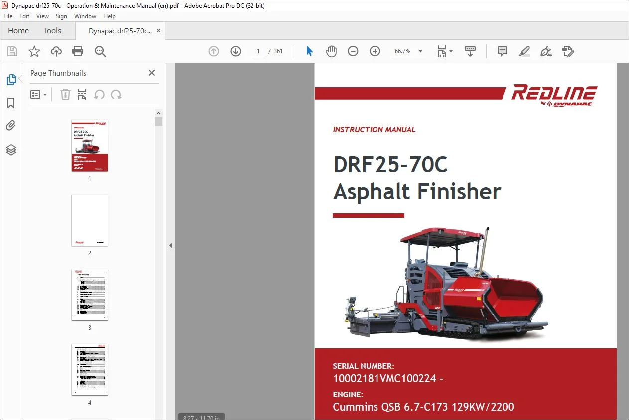
Dynapac DRF25-70C Asphalt Finisher Operation & Maintenance Instruction Manual 4812209453_B – PDF DOWNLOAD
SERIAL NUMBER:
10002181VMC100224 –
ENGINE:
Cummins QSB 6.7-C173 129KW/2200
Description
Dynapac DRF25-70C Asphalt Finisher Operation & Maintenance Instruction Manual 4812209453_B – PDF DOWNLOAD
FILE DETAILS:
Dynapac DRF25-70C Asphalt Finisher Operation & Maintenance Instruction Manual 4812209453_B – PDF DOWNLOAD
Language : English
Pages : 361
Downloadable : Yes
File Type : PDF
Size: 28.5 MB
TABLE OF CONTENTS:
Dynapac DRF25-70C Asphalt Finisher Operation & Maintenance Instruction Manual 4812209453_B – PDF DOWNLOAD
SERIAL NUMBER:
10002181VMC100224 –
ENGINE:
Cummins QSB 6.7-C173 129KW/2200
V Preface 1
1 General safety instructions 2
1 1 Laws, guidelines, accident prevention regulations 2
1 2 Safety signs, signal words 3
“Danger”! 3
“Warning” ! 3
“Caution” ! 3
“Note” ! 3
1 3 Other supplementary information 3
1 4 Warnings 4
1 5 Prohibitive symbols 6
1 6 Protective equipment 7
1 7 Environmental protection 8
1 8 Fire prevention 8
1 9 Additional information 9
3 Guarantee conditions 10
4 Residual risks 11
5 Sensibly predictable incorrect usage 12
A Correct use and application 1
B Vehicle description 1
1 Application 1
2 Description of assemblies and functions 2
2 1 Vehicle 3
Construction 3
3 Danger zones 7
4 Safety devices 8
5 Technical data, standard configuration 10
5 1 Dimensions (all dimensions in mm) 10
5 2 Allowed angle of rise and slope 11
5 3 Permissible approach angle 11
5 5 Weights DRF25-70C (all weights in t) 12
5 7 Performance data DRF25-70C 14
5 8 Travel drive/traction unit 15
5 10 Engine DRF25-70C 15
5 11 Hydraulic system 15
5 12 Material compartment (hopper) 16
5 13 Material transfer 16
5 14 Material distribution 16
5 15 Screed lifting device 17
5 16
5 17
Electrical system 17
Permissible temperature ranges 17
2
6 Identification points 18
6 1 Warning signs 21
6 2 Information signs 24
6 4 Instructive symbols, prohibitive symbols, warning symbols 27
6 5 Danger symbols 28
6 6 Further warnings and operating instructions 29
6 7 Identification label for the paver finisher (41) 31
6 8 Explanation of 17-digit PIN serial number 32
6 9 Engine type plate 33
7 EN standards 34
7 3 Continuous sound pressure DRF25-70C, Cummins QSB 6 7-C173 35
7 4 Operating conditions during measurement 35
7 5 Vibration acting on the entire body 36
7 6 Vibrations acting on hands and arms 36
7 7 Electromagnetic compatibility (EMC) 36
C10 Transportation 1
1 Safety regulations for transportation 1
2 Transportation on low-bed trailers 4
2 1 Preparations 4
3 Securing the load 6
3 1 Prepare the low-bed trailer 6
3 2 Driving onto the low-bed trailer 7
3 3 Lashing equipment 8
3 4 Loading 9
3 5 Preparing the vehicle 10
4 Securing the load 11
4 1 Securing at the sides 11
4 2 Securing at the front 11
4 3 Securing at the rear – screed with side board 12
4 4 Securing at the rear – screed without side board 13
Step 1: fasten lashing straps 13
Step 2: fasten lashing chains 13
4 5 After transportation 14
Protective roof 15
5 Transportation 17
5 1 Preparations 17
5 2 Driving mode 19
6 Loading by crane 20
7 Towing 23
8 Safely parking the vehicle 25
8 1 Lifting the vehicle with hydraulic lifts, lifting points 26
3
D10 Operation 1
1 Safety regulations 1
2 Controls 3
2 1 Operating panel 3
3 Remote control 40
D30 Mode of operation 1
1 Operating elements on the paver finisher 1
1 1 Control elements on the operator’s control station 1
Protective roof 2
Ladder 4
Storage space 4
Protective roof 8
Seat console 11
Fuse box 14
Batteries 15
Main battery switch 15
Hopper transport safeguard 16
Screed lock, mechanical 16
Paving thickness indicator 18
Auger lighting (o) 19
LED working light (o) 20
Auger height adjustment ratchet (o) 22
Auger height displays 22
Sensor rod / sensor rod extension 23
Manual separator fluid spray (o) 25
Separator fluid spraying system (o) 26
Conveyor limit switches –
conventional version 28
Ultrasonic auger limit switches
(left and right) – conventional version 30
4
24 volt / 12 volt sockets (o) 31
Pressure control valve for screed charging/relieving 32
Pressure control valve for paving stop with relieving 32
Manometer for screed charging/relieving 32
Screed eccentric adjustment 36
Push roller crossbar, adjustable 37
Push roller damping, hydraulic (o) 38
Fire extinguisher (o) 39
Rotary beacon (o) 40
Fuelling pump (o) 41
D40 Mode of operation 1
1 Preparing for operation 1
Required devices and aids 1
Before starting work
(in the morning or when starting paving) 3
Check list for the machine operator 3
1 1 Starting the paver finisher 6
Before starting the paver finisher 6
“Normal” starting 6
External starting (starting aid) 8
After starting 11
Observe indicator lamps 13
Engine coolant temperature check (1) 13
Battery charge indicator (2) 13
Oil pressure indicator lamp for the diesel engine (3) 13
1 2 Preparation for transportation 15
Driving and stopping the paver finisher 17
1 3 Preparations for paving 18
Separator fluid 18
Screed heater system 18
Direction marks 19
Loading/conveying material 21
1 4 Starting for paving 23
1 5 Checks during paving 24
5
Paver function 24
Quality of the layer 24
1 6 Paving with “screed control at paver finisher stop”
and “screed charging/relieving” 25
General 25
Screed charging/relieving 27
Screed control with paver finisher stop / in paving operation
(screed stop / floating stop / floating paving) 27
Screed control with paver finisher stop – floating stop with relief 29
Adjusting the pressure 29
Set pressure for screed charging
or relieving 29
Setting pressure for screed control with paver finisher stop –
floating stop with relief 31
1 7 Interrupting/terminating operation 33
During breaks in paving (e g delay due to material trucks) 33
During extended interruptions
(e g lunch break) 33
When work is finished 35
2 Malfunctions 36
2 1 Error code query for engine 36
Output of numerical code 38
2 2 Error codes 40
2 3 Problems during paving 47
2 4 Malfunctions on the paver finisher or screed 49
E10 Set-up and modification 1
1 Special notes on safety 1
2 Distribution auger 2
2 1 Height adjustment 2
Grain sizes up to 16 mm 2
Grain sizes > 16 mm 2
2 2 Mechanical adjustment
with ratchet (o) 3
2 3 Hydraulic adjustment (o) 3
2 4 Height adjustment for large working widths / with brace 4
3 Auger extension 6
3 1 Mounting extension parts 7
Mounting the material shaft and auger extension 7
Mounting the outer auger bearing 8
Mounting the auger end bearing 9
3 2 Auger extension chart 10
Auger upgrading, working width 3 14 m 12
Auger upgrading, working width 3 78 m 12
Auger upgrading, working width 4 42 m 12
Auger upgrading, working width 5 06 m 13
Auger upgrading, working width 5 70 m 13
Auger upgrading, working width 6 34 m 14
Auger upgrading, working width 6 98 m 15
6
3 3 Mounting the auger brace 19
3 4 Aligning the auger 21
3 5 Material shaft, hinged 22
3 6 Hopper scraper 23
3 7 Crossbeam guide 24
4 Offsetting the screed 25
5 Levelling 26
5 1 Slope controller 26
5 2 Fitting the height sensing device 27
5 3 Mounting the grade control system 27
5 4 Setting up the sensor arm 28
5 5 Big ski 9 m 29
Mounting the big ski bracket on the crossbeam 31
Mounting the swivel arms 32
Mounting the center element 33
Extending the big ski 34
Mounting the sensor bracket 35
Mounting and aligning the sensors 36
Mounting the distributor box 37
Connection diagram 38
5 6 Levelling shoe 6m, 9m 39
10 Limit switch 49
10 2 Auger limit switches (left and right) –
mounting the conventional version 49
7
13 Screed 70
13 1 Electrical connections side board – screed – Conventional version 70
13 2 Electrical connections side board – screed PLC version 72
F10 Maintenance 1
1 Notes regarding safety 1
F20 Maintenance review 1
1 Maintenance review 1
F30 Maintenance – conveyor 1
1 Maintenance – conveyor 1
1 1 Maintenance intervals 3
1 2 Points of maintenance 4
Chain tension, conveyor (1) 4
Conveyor drive – drive chains (2) 6
Conveyor deflectors / conveyor plates (3) 7
F40 Maintenance – auger assembly 1
1 Maintenance – auger assembly 1
1 1 Maintenance intervals 3
1 2 Points of maintenance 5
Outer auger bearing (1) 5
Auger planetary gear (2) 6
Drive chains of the
augers (3) 7
Auger box (4) 8
Seals and sealing rings (5) 9
Gearbox bolts Check tightening (6) 10
Mounting screws – Outer auger bearing
Check tightening (7) 11
Auger blade (8) 12
8
F50 Maintenance – engine assembly Tier 3 1
1 Maintenance – engine assembly 1
1 1 Maintenance intervals 3
1 2 Points of maintenance 6
Engine fuel tank (1) 6
Engine lube oil system (2) 7
Engine fuel system (3) 10
Engine air filter (4) 12
Engine cooling system (5) 14
Engine drive belt (6) 16
F60 Maintenance – hydraulic system 1
1 Maintenance – hydraulic system 1
1 1 Maintenance intervals 3
1 2 Points of maintenance 5
Hydraulic oil tank (1) 5
Suction/return flow hydraulic filter (2) 7
Bleeding the filter 8
Ventilation filter 8
High-pressure filter (3) 9
Pump distribution gear (4) 10
Bleeder 11
Hydraulic hoses (5) 12
Marking hydraulic hoses / storage period, period of use 14
Auxiliary flow filter (6) 15
F73 Maintenance – drive units 1
1 Maintenance – drive units 1
1 1 Maintenance intervals 3
1 2 Points of maintenance 6
Chain tension (1) 6
Bottom plates (2) 9
Rollers (3) 10
Planetary gear (4) 11
Screw connections 13
9
F80 Maintenance – electrical system 1
1 Maintenance – electrical system 1
1 1 Maintenance intervals 3
1 2 Maintenance points 4
Batteries (1) 4
Recharging the batteries 5
Alternator (2) 6
Cleaning the alternator 7
Electrical fuses / relays (3) 8
Fuses 8
Relays in the engine compartment 11
Relays in terminal box 12
Relays in operating panel 14
Relay in connection box under the operating platform 15
F90 Maintenance – lubricating points 1
1 Maintenance – lubricating points 1
1 1 Maintenance intervals 2
1 2 Points of maintenance 3
Central lubrication system (1) 3
Bearing points (2) 7
F100 Tests, stopping 1
1 Tests, checks, cleaning, stopping 1
1 1 Maintenance intervals 2
2 General visual inspection 3
3 Check that the bolts and nuts fit firmly 3
4 Inspection by an expert 4
5 Cleaning 5
5 1 Cleaning the hopper 6
5 2 Cleaning the conveyor and auger 6
5 3 Cleaning optical or acoustic sensors 7
6 Preserving the paver finisher 8
6 1 Shutdowns for up to 6 months 8
6 2 Shutdowns lasting from 6 months to 1 year 8
6 3 Recommissioning the machine 8
7 Environmental protection, disposal 9
7 1 Environmental protection 9
7 2 Disposal 9
8 Bolts – torques 10
8 1 Standard metric threads – strength class 8 8 / 10 9 / 12 9 10
8 2 Fine metric threads – strength class 8 8 / 10 9 / 12 9 11
10
F110 Lubricants and
operating substances 1
1 Lubricants and operating substances 1
1 1 Capacities 3
2 Lubricant specifications 4
2 1 Engine 4
2 2 Cooling system 4
2 3 Hydraulic system 4
2 4 Pump distribution gear 4
2 5 Drive unit planetary gear 5
2 6 Auger drive planetary gear 5
2 7 Auger box 5
2 8 Grease 5
2 9 Separator emulsion 6
2 10 Hydraulic oil 7
IMAGES PREVIEW OF THE MANUAL:
PLEASE NOTE:
- This is the SAME exact manual used by your dealers to fix your vehicle.
- The same can be yours in the next 2-3 mins as you will be directed to the download page immediately after paying for the manual.
- Any queries / doubts regarding your purchase, please feel free to contact [email protected]
S.V