DYNAPAC High Capacity Planer PL2000F (IIIAT3) PL2000F (IVT4f) Operating & Maintenance Instructions Manual PDF DOWNLOAD
$28.95
DYNAPAC High Capacity Planer PL2000F (IIIAT3) PL2000F (IVT4f) Operating & Maintenance Instructions Manual PDF DOWNLOAD
Operating & Maintenance
4812313240.pdf
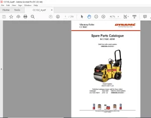
High capacity planer PL2000F (IIIAT3) PL2000F (IVT4f)
Diesel engine CumminsQSX15-600
IIIA T3: 10000905J0C005866
IV T4f: 10000906A0C005587
Description
DYNAPAC High Capacity Planer PL2000F (IIIAT3) PL2000F (IVT4f) Operating & Maintenance Instructions Manual PDF DOWNLOAD
FILE DETAILS:
DYNAPAC High Capacity Planer PL2000F (IIIAT3) PL2000F (IVT4f) Operating & Maintenance Instructions Manual PDF DOWNLOAD
Language : English
Pages :307
Downloadable : Yes
File Type : PDF
IMAGES PREVIEW OF THE MANUAL:
TABLE OF CONTENTS:
DYNAPAC High Capacity Planer PL2000F (IIIAT3) PL2000F (IVT4f) Operating & Maintenance Instructions Manual PDF DOWNLOAD
Operating & Maintenance
4812313240.pdf
High capacity planer PL2000F (IIIAT3) PL2000F (IVT4f)
Diesel engine CumminsQSX15-600
IIIA T3: 10000905J0C005866
IV T4f: 10000906A0C005587
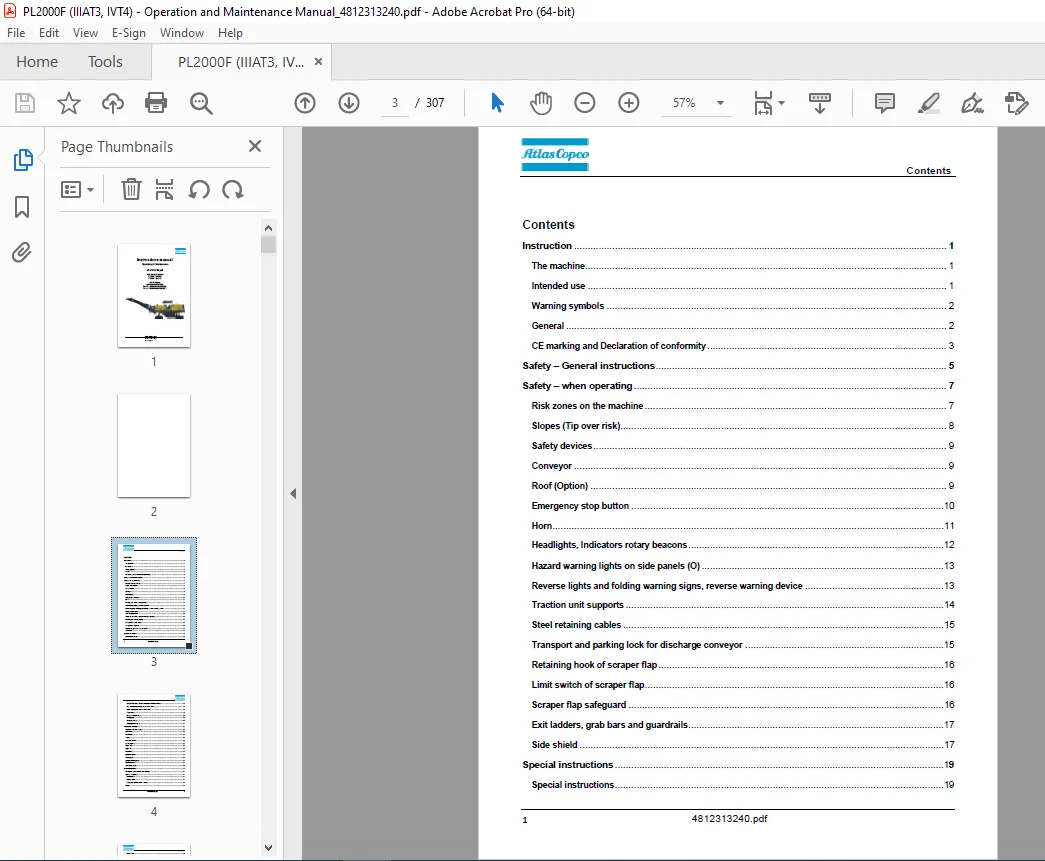
Instruction 1
The machine 1
Intended use 1
Warning symbols 2
General 2
CE marking and Declaration of conformity 3
Safety – General instructions 5
Safety – when operating 7
Risk zones on the machine 7
Slopes (Tip over risk) 8
Safety devices 9
Conveyor 9
Roof (Option) 9
Emergency stop button 10
Horn11
Headlights, Indicators rotary beacons12
Hazard warning lights on side panels (O) 13
Reverse lights and folding warning signs, reverse warning device 13
Traction unit supports 14
Steel retaining cables 15
Transport and parking lock for discharge conveyor 15
Retaining hook of scraper flap 16
Limit switch of scraper flap16
Scraper flap safeguard 16
Exit ladders, grab bars and guardrails17
Side shield 17
Special instructions 19
Special instructions19
Contents2
Standard lubricants and other recommended oil and fluids19
High ambient temperatures, above +40°C (104°F)19
Lower ambient temperature – Freeze risk19
Temperatures19
High pressure cleaning 20
Fire fighting 20
Battery handling20
Jumping starting (24V) 21
Technical specifications23
Vibrations – Operator station23
Noise level 23
Dimensions 24
Weights26
Performance data 26
Loading system27
Engine (T3)27
Engine (T4)27
Travel drive 27
Hydraulic system28
Water system 28
Compressed air system28
Electrical system28
Tightening torques 29
Machine description31
Descriptions of assemblies and functions31
Machine description 44
Identification44
Machine plate44
Explanation of 17PIN serial number 45
Decals46
Contents3
Safety decals 49
Info decals 53
Instruments/Controls54
Control panel 54
Switch panel 57
Main console – right 57
Main console – left 58
RH – Joystick panel 57
LH – Joystick panel 57
RH/LH – Ergo control66
Front remote control69
Rear remote control71
Screen structure for setting and display options74
Description of error codes, dialog boxes 91
Electrical system109
Fuses, boxes109
Relay, machine110
Driver’s seat on left/right 111
Battery’s main switch 112
Batteries 112
Tilt display 113
Folding ladder 114
Guardrail 115
Transport position for ladder and guardrails 116
Hydraulic folding roof operation 117
Hydraulic hood operations118
Throttle valves for deployment speed of hood and roof 119
Manual pump, hood and roof 119
Water system 120
High pressure cleaner 121
Contents4
Filling pump for water tank 122
Water filling (pressure fill) connection for water tank123
Changeover for separate circuits of rear strut towers 124
Grading depth display 125
Milling drum operation check125
Interlock on scraper flap126
Retaining hook of scraper flap 126
Limit switch of scraper flap127
Traction unit supports 128
Support brackets128
“Scraper flap function changeover” valve 129
“Discharge conveyor function changeover” valve 129
Transport and parking lock for discharge conveyor 130
Monitoring camera (O) 131
Compressed air system132
Storage area and protective flaps133
Plumb fixture134
Swivel-mounted warning sign135
Tool holder135
Typical wear marks on tool holder 136
Typical wear marks on bits137
Dismantling the bits 138
Mounting the bits 138
Removing the quick-charge tops (model 1) 138
Removing the quick-charge tops (model 2) 139
Mounting the quick-charge tops (model 1) 139
Mounting the quick-charge tops (model 2) 139
Replacing the bit box 140
Replacing the holder box141
Leveling unit 142
Contents5
Matric type 142
Operating the Atlas Copco Dynapac Leveling System143
Setting the contrast143
Symbols and displays in the working window144
Sensor selection 145
Operating with the Cross-Slope sensor147
Zero adjustment 151
Sensitivity setting 153
Changing the measurement units 155
System languages156
Operation 157
Before starting 157
Preparing for operation 157
Devices and aids157
Before starting work158
Starting the machine 159
External starting (starting aid) 161
Allowing engine to “warm up” 162
Driving the machine 163
Milling (preparation) 164
Milling operations using set-up button167
Parking the machine169
Preserving the water spraying system 170
Long-term parking 171
Long-term parking171
Battery 171
Engine 171
Watering system 171
Hoods, tarpaulin171
Fuel tank 172
Contents6
Hydraulic reservoir 172
Miscellaneous173
Transport 173
Safety regulations for transport 173
Fix points175
Transport on trailers177
Transport and parking lock for discharge conveyor 181
Normal on-road travel182
Hydraulically foldable discharge conveyor183
Folding in discharge conveyor 183
Folding out discharge conveyor 184
Load by crane 185
Towing precedure186
Securing before parking up 187
Operating instructions – Summary 189
Preventive maintenance191
Maintenance – Lubricants and symbols193
Maintenance – Lubricants and symbols 193
Fluid volumes194
Maintenance 195
Notes regarding safety for maintenance195
Liability exclusion in case of use of non-original spare or wear parts as well as incorrect operating
materials 196
Maintenance intervals196
Engine drive unit 209
Fuel tank 209
Cleaning tank and system210
Diesel engine 210
Engine oil drainage point 211
Oil filter 212
Contents7
Fuel filter212
Fuel filter water separator 213
Air filter213
Cooler 214
Coolant filter 214
Cooler 215
Drive belt215
Valve clearance 216
Engine brackets, left/right216
Connecting screws, pump distribution transmission/engine217
Hydraulic system218
Hydraulic oil tank 218
Hydraulic oil drainage valve218
High-pressure hydraulic filter 219
Return hydraulic filter220
Pump distribution transmission221
Oil level check221
Oil cooler 222
Bleeder 223
Oil cooler 223
Hydraulic hoses 224
Hydraulic unit for roof and hood activation 224
Oil level check224
Traction units 225
Planetary gear – oil level check225
Oil change225
Chain tension226
Bottom plate227
Rubber pad 227
Steering system sliding parts, steering arms, stop ring and scraper 228
Contents8
Retaining device for track rod and steering cylinder bolts 229
Belt drive229
Clutch “DESCH” Type 230
Clutch “STROMAG” Type 231
Milling drum gear box232
Oil level check232
Oil change233
Milling drum234
Draining coolant234
Checking fluid level/adding fluid 235
Scrapers and supporting wear bar (moldboard)235
Runners on the side boards236
Sliding shoe runners 237
Drum flap limit switch238
Milling drum housing fastening bolts 238
Loading equipment239
Drum holder 241
Steel cords241
Funnel rubber of transfer point and sealing rubbers/guides242
Water system 243
Water tank243
Feed pump 245
Water filter 246
Water pump247
Spray nozzles247
Power supply 248
Batteries 248
Compressed air system249
Maintenance unit and compressed air system249
Leveling system 250
Contents9
Sensor, controllers, connection cables 250
Emergency stop button 250
Lubrication points 251
Traction unit251
Chassis legs251
Steering cylinder 251
Floating pin251
Milling section 252
Belt tensioner252
Clutch bearing type “DESCH” 252
Clutch bearing type “STROMAG”253
Steering hydraulic cylinder 253
Milling drum bearing254
Upper/lower conveyor 255
Drive roller tension bearing 255
Upper conveyor (foldable model) 256
Tail roller pedestal bearing 256
Drive roller tension bearing 256
Springs, joints and bolts256
Flange bolts 257
Lower conveyor257
Drive roller tension bearing 257
Inspection 258
Disposal259
Appendix 1
Appendix 1: Engine Fault Code 1
Appendix 2: Check list for machine operator34
PLEASE NOTE:
- This is the same manual used by the dealers to diagnose and troubleshoot your vehicle
- You will be directed to the download page as soon as the purchase is completed. The whole payment and downloading process will take anywhere between 2-5 minutes
- Need any other service / repair / parts manual, please feel free to contact [email protected] . We still have 50,000 manuals unlisted
S.S