Trusted Business
Verified & Licensed
Virus Free Files
100% Safe Downloads
Secure Payment
SSL Protected
Instant Delivery
Available Immediately
DYNAPAC Pavers F1000T Operation & Maintenance Manual PDF DOWNLOAD
$27.95
DYNAPAC Pavers F1000T Operation & Maintenance Manual PDF DOWNLOAD
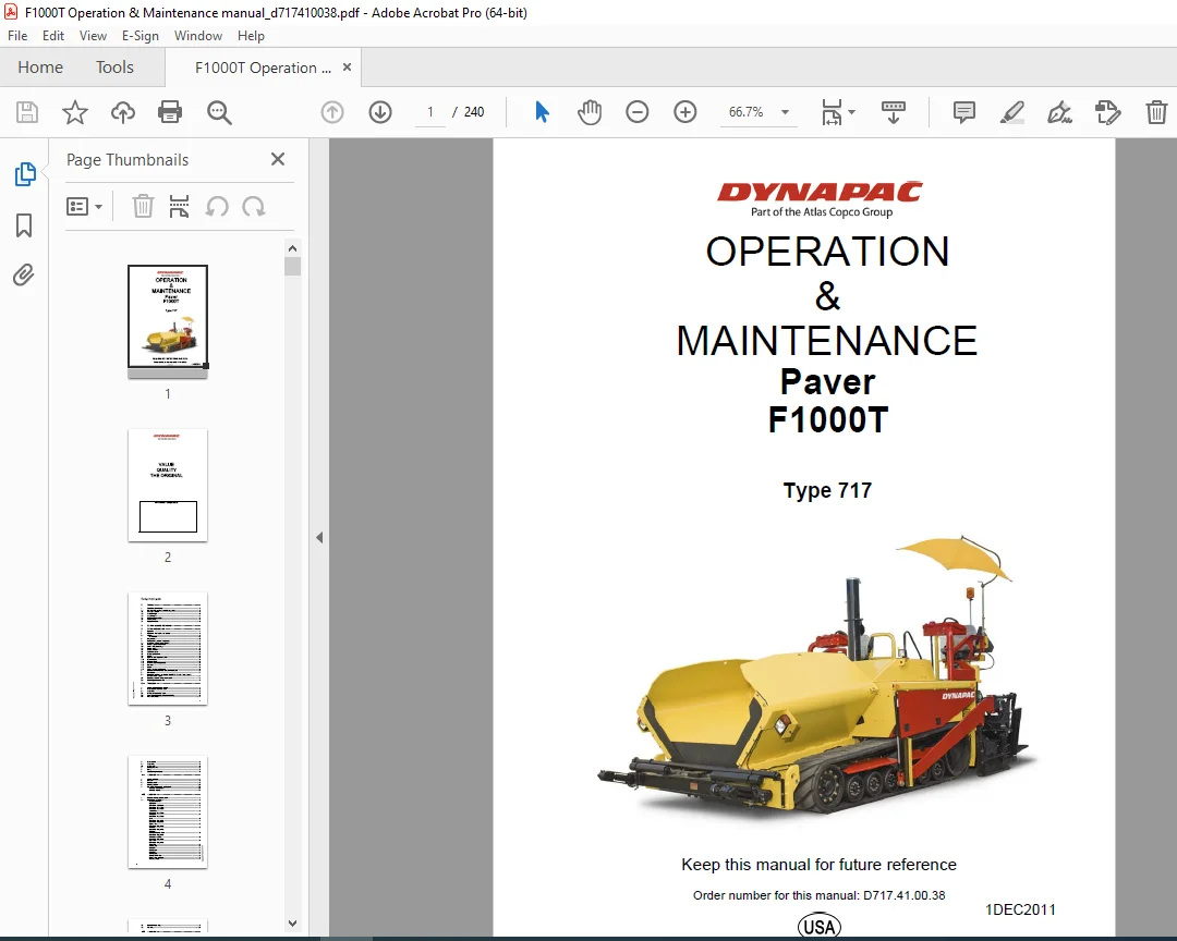
OPERATION&MAINTENANCE
Paver F1000T
Type 717
Instant PDF Download
Available immediately
Save to Your Device
Download & keep forever
Antivirus Scanned
100% virus-free
Trusted Worldwide
175,000+ customers
Description
DYNAPAC Pavers F1000T Operation & Maintenance Manual PDF DOWNLOAD
FILE DETAILS:
DYNAPAC Pavers F1000T Operation & Maintenance Manual PDF DOWNLOAD
Language : English
Pages :240
Downloadable : Yes
File Type : PDF
IMAGES PREVIEW OF THE MANUAL:
TABLE OF CONTENTS:
DYNAPAC Pavers F1000T Operation & Maintenance Manual PDF DOWNLOAD
OPERATION&MAINTENANCE
Paver F1000T
Type 717
1DEC2011 1
VALUE 2
QUALITY 2
THE ORIGINAL 2
Your Authorized Dynapac Dealer: 2
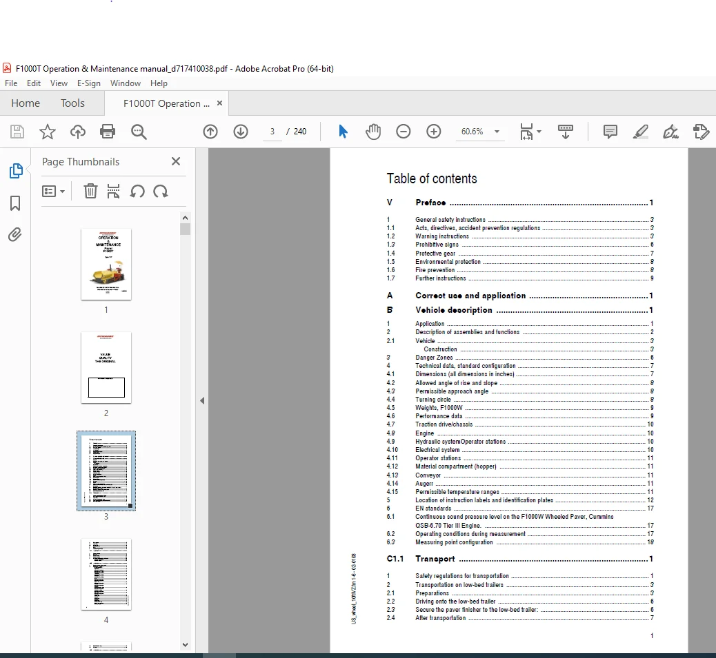
Table of contents 3
V Preface 1 3
1 General safety instructions 3 3
11 Acts, directives, accident prevention regulations 3 3
12 Warning instructions 3 3
13 Prohibitive signs 6 3
14 Protective gear 7 3
15 Environmental protection 8 3
16 Fire prevention 8 3
17 Further instructions 9 3
A Correct use and application 1 3
B Vehicle description 1 3
1 Application 1 3
2 Description of assemblies and functions 2 3
21 Vehicle 3 3
3 Danger Zones 6 3
4 Technical data, standard configuration 7 3
41 Dimensions (all dimensions in inches) 7 3
42 Allowed angle of rise and slope 8 3
43 Permissible approach angle 8 3
44 Turning circle 8 3
45 Weights, F1000W 9 3
46 Performance data 9 3
47 Traction drive/chassis 10 3
48 Engine 10 3
49 Hydraulic systemOperator stations 10 3
410 Electrical system 10 3
411 Operator stations 11 3
412 Material compartment (hopper) 11 3
413 Conveyor 11 3
414 Augerr 11 3
415 Permissible temperature ranges 11 3
5 Location of instruction labels and identification plates 12 3
6 EN standards 17 3
61 Continuous sound pressure level on the F1000W Wheeled Paver, Cummins QSB-670 Tier III Engine 17 3
62 Operating conditions during measurement 17 3
63 Measuring point configuration 18 3
1 Safety regulations for transportation 1 3
2 Transportation on low-bed trailers 3 3
21 Preparations 3 3
22 Driving onto the low-bed trailer 6 3
23 Secure the paver finisher to the low-bed trailer: 6 3
24 After transportation 7 3
3 Transportation 8 4
31 Preparations 8 4
32 Driving mode 11 4
4 Loading by crane 13 4
5 Towing 15 4
6 Safely parking the vehicle 16 4
1 Safety regulations 1 4
2 Controls 2 4
21 Operating panel 2 4
3 Auxiliary functions 25 4
4 Left / right remote controls and handsets 27 4
D20 Operation 1 4
1 Operation of the graphical terminal 1 4
11 Navigation using Soft Keys 2 4
12 Engine Error messages 18 5
13 FMI-codes 23 5
D30 Operation 1 5
1 Operating elements on the paver 1 5
D40 Operation 1 5
1 Preparation of operation 1 5
11 Starting the paver 5 5
12 Transport Operation 11 5
13 Preparations for paving 12 5
14 Starting for paving 16 5
15 Check during paving 17 5
16 Interrupting/terminating operation 19 5
2 Malfunctions 22 6
21 Problems during paving 22 6
22 Malfunctions on the paver or screed 24 6
E10 Set-up and modification 1 6
1 Special notes on safety 1 6
2 Auger 2 6
21 Height adjustment 2 6
22 Auger crossbeam – hydraulic height adjustment 2 6
23 Auger extension 3 6
24 Mounting extension parts 4 6
25 Mounting support tube extensions 5 6
26 Installing tunnel plates 6 6
27 Installing additional braces 7 6
3 Screed 8 6
4 Electrical connections 8 6
41 Remotes from screed to paver 8 6
42 Right hand conveyor sensor control 8 6
43 Right hand auger sensor control 8 6
44 Left hand conveyor sensor control 9 6
45 Left hand auger sensor control 9 6
46 Auger Chart 10 6
F10 Maintenance 1 6
1 Notes regarding safety 1 6
F21 Maintenance Overview 1 6
1 Maintenance overview 1 6
F30 Maintenance – Conveyor 1 6
1 Maintenance – Conveyor 1 6
11 Maintenance intervals 2 6
12 Points of maintenance 3 6
F40 Maintenance – Auger 1 6
1 Maintenance – Auger sub-unit I 1 6
11 Maintenance intervals 2 6
12 Points of maintenance 3 6
F50 Maintenance – Engine 1 7
1 Maintenance – engine sub-unit 1 7
11 Maintenance intervals 2 7
12 Points of maintenance 4 7
F60 Maintenance – Hydraulic System 1 7
1 Maintenance – hydraulic system 1 7
11 Maintenance intervals 2 7
12 Hydraulic System 3 7
13 Points of maintenance 4 7
1 Maintenance – travel drive, steering 1 7
11 Maintenance intervals 2 7
12 Points of maintenance 3 7
F81 Maintenance – Electronic System 1 7
1 Maintenance – Electronic system 1 7
11 Maintenance intervals 2 7
12 Points of maintenance 3 7
F90 Maintenance – Lubricating Points 1 7
1 Maintenance – Lubricating points 1 7
11 Maintenance intervals 2 8
12 Points of maintenance 3 8
F100 Checks, Decommissioning 1 8
1 Tests, check-up, cleaning, stopping 1 8
11 Maintenance intervals 2 8
2 General observation 3 8
3 Check performed by a specialist 3 8
4 Cleaning 4 8
5 Preservation for storage of paver 5 8
51 Downtime up to 6 months 5 8
52 Downtime between 6 months and 1 year 5 8
53 Re-commissioning: 5 8
1 Lubricants and operating substances 1 8
11 Capacities 2 8
V Preface 9
1 General safety instructions 11
11 Acts, directives, accident prevention regulations 11
12 Warning instructions 11
13 Prohibitive signs 14
14 Protective gear 15
15 Environmental protection 16
16 Fire prevention 16
17 Further instructions 17
A Correct use and application 19
B Vehicle description 21
1 Application 21
The DYNAPAC F1000T is a rubber track paver that is used for laying bituminous mixed material, roll-down or lean-mixed concrete, track-laying ballast and unbound mineral aggregates for paving foundations 21
2 Description of assemblies and functions 22
21 Vehicle 23
The Dynapac F1000T is a rubber track propelled paver built with a welded steel frame on which the power pack, augers, conveyors, hopper and operator positons are mounted 23
The track suspension compensates for uneven areas on the ground The suspension of the attached screed helps to attain high pavi 23
The operation of the paver is largely facilitated by the easy to use operator controls The operator can control the functions of the paver from either the left control panel or the right control panel 23
Available options include: 23
Engine: The paver is powered by a 6-cylinder, water cooled diesel engine with direct injection and a turbo charger Electric sta 24
Track: The two rubber tracks are driven indepently of each other They are each direct drive requiring less maintenance and serv 24
Hydraulic system: The diesel engine has the Pump Drive gear box attached to it This drives the hydraulic pumps for all of the m 24
Track drive: The closed-loop track drive system includes two speed track drive motors that are connected to the drive pumps by m 24
Steering system/operator’s platform: The independent hydrostatic travel drives allow the paver to be turned on the spot The ele 24
Push roller crossbar: The push rollers for material trucks are connected to a crossbar that pivots at its center This crossbar 24
Material compartment (hopper): The hopper inlet is equipped with a conveyor system that empties the hopper and transfers the mat 24
Conveyors (Material transfer): The paver is equipped with two conveyors driven separately with pressure from a single pump The 24
Augers: The augers are driven and controlled independently from the conveyors The auger hydraulics consist of two high pressure 25
Height adjustment and extension of augers: Height adjustment and extension of augers ensure an optimum variety of a wide range o 25
Levelling/slope control system: The slope control system allows the paving thickness to be regulated at the left-hand or the rig 25
The slope control system always operates in conjunction with the screed height adjustment of the opposite side 25
By adjusting the height of the screed leveling cylinders, the paving thickness of the material or the laying height of the scree 25
Screed lifting arms: The screed lifting arms are used to lift the screed during transport Lifting occurs electro-hydraulically 25
Truck hitch (option): The truck hitch holds the transport vehicle, containing the paving material, in contact with the paver The truck hitch mounts are located on the front of the hopper 25
3 Danger zones 26
4 Technical data, standard configuration 27
41 Dimensions 27
42 Allowed angle of rise and slope 28
43 Permissible approach angle 28
44 Weights, F1000T 29
45 Performance data 29
46 Engine 30
47 Hydraulic system 30
48 Material compartment (hopper) 30
49 Electrical system 30
410 Operator stations 30
411 Conveyors 31
412 Auger 31
413 Permissible temperature ranges 31
5 Location of instruction labels and identification plates 32
51 Identification label for the paver (6) 35
6 EN standards 36
61 Continuous sound pressure level on the F1000T Track Paver, Cummins QSB- 670 Tier III Engine 36
Sound pressure level at the operator’s position (at the height of the head): LH Console RH Console 36
LAF = 935 dB(A) 926 dB(A) 36
Sound capacity level: LWA = 12234 dB(A) 36
Sound pressure level at the machine 36
62 Operating conditions during measurement 36
The diesel engine was running at maximum speed The screed was in working position, lowered to a rubber mat Tamper and vibratio 36
63 Measuring point configuration 37
Hemispherical measuring surface with a radius of 525 ft (16 m) The machine was at the center The measuring points had been assigned the following coordinates: 37
1 Safety regulations for transportation 39
Additional stipulations for transportation on public roads: 39
2 Transportation on low-bed trailers 41
21 Preparations 41
22 Driving onto the low-bed trailer 44
23 Secure the paver to the low-bed trailer: 44
24 After transportation 45
3 Transportation 46
31 Preparations 46
32 Driving mode 49
4 Loading by crane 51
5 Towing 53
Use only approved tow bars! 53
If necessary, remove any attachments and accessories from the paver and the screed until the basic width has been attained 53
A hand pump is located in the engine compartment (left) that must be activated to be able to tow the machine Pressure for releasing the track drive system brakes is built up with the hand pump 53
After towing, return the Pump Pressure Lock and Release Handle (2) to the UP position This will release pressure in the Hand Pump and will allow the braking system to engage 53
The track drive system brakes are now reactivated and the machine is secured against rolling 53
6 Safely parking the vehicle 54
When the paver is parked at a location accessible to the public, it must be secured in such a way that unauthorized persons or playing children cannot damage the vehicle 54
D 10 Operation 55
1 Safety regulations 55
2 Controls 56
21 Operating panel 56
3 Auxiliary functions 78
4 Left / right remote controls and handsets 80
Left / right remote control 81
D 20 Operation 97
1 Operation of the graphical terminal 97
11 Navigation using Soft Keys 98
12 Engine Error messages114
13 FMI-codes119
D 30 Operation121
1 Operating elements on the paver121
Operator’s platform121
Seat console121
Operating panel121
Driver’s seat122
Batteries122
Battery main switch123
Transport safeguards for the hopper124
Mechanical screed transport safeguard (to the left and the right beneath the driver’s seat)124
Paving thickness indicator125
Release Agent System126
On/Off switch of working lights (1)127
On/Off switch hazard flasher (2):127
Warning Beacon127
Conveyor limit sensors128
Ultrasonic auger limit sensors (left and right)128
Sockets 24V128
D 40 +Operation129
1 Preparation of operation129
To avoid delays on site, check before starting work whether or not the following equipment and tools are present:129
11 Starting the paver133
Before starting the diesel engine and beginning operation, the following steps must be performed:133
Check the operating hours counter to determine whether or not additional maintenance work (such as monthly or yearly maintenance) must be performed133
Starting is not possible if the drive lever is not in the central position or if the emergency stop button (40) is depressed,133
The engine can be started with the help of an external power source if the batteries are low and the starter no longer turns135
Suitable power sources are:135
Standard 12V chargers or quick chargers cannot be used for jump starting135
Check for proper polarity! Always connect the negative cable last and remove it first!135
To increase the engine speed:137
Let the paver warm up for about 5 minutes if the engine is cold137
Read and follow Chapter D2 of this manual for possible warnings on the graphical terminal!137
12 Transport Operation139
The remote control must be connected and this function must be set to “Manual“139
Engage both screed transport safeguards to secure the screed in the raised position139
13 Preparations for paving140
Spray the parts coming into contact with asphalt (hopper, screed, auger, push roller) with a separator emulsion140
Switch the screed heater “On” for about 15-30 minutes (depending on the ambient temperature) before paving begins Warming up prevents the material from sticking to the screed plates140
To ensure straight paving, a direction mark must be present or established (road edge, chalk lines or similar)140
Conveyor and auger will begin to work142
The limit sensors for the conveyors and augers must switch off the function when the material has reached the height limit in the area beneath the auger crossbeam (conveyor sensors) or at the auger ends (auger sensors)142
Check that the material is being conveyed properly142
14 Starting for paving144
Set the switches, levers and controls listed below to the specified positions when the screed has reached its operating temperature and a sufficient amount of material lies in front of the screed:144
Carry out the check in the area of the drive chains or wheels as the screed tends to level an uneven ground The reference points for the layer thickness are the drive chains or wheels144
The basic screed setting must be corrected when the actual layer thickness deviates significantly from the values needed for the job requirement (see the operating instructions for the screed)144
15 Check during paving145
The following points must be constantly observed during paving:145
NOTE:145
See the section D4 ”Malfunctions” when paver functions fail145
NOTE:145
See section D 4 ”Malfunctions, Problems during Paving” if the paving quality is poor145
16 Interrupting/terminating operation147
Screed will be switched into “STOP“ function automatically147
Screed will be switched into “STOP“ function automatically147
The screed must be heated up to the correct paving temperature before paving can be resumed147
Do not turn the main switch off until 15 seconds after the ignition has been turned off! The engine electronics requires this length of time to back up data149
2 Malfunctions150
21 Problems during paving150
22 Malfunctions on the paver or screed152
E 01 Set-up and modification155
1 Special notes on safety155
2 Auger156
21 Height adjustment156
22 Auger crossbeam – hydraulic height adjustment156
23 Auger extension157
24 Mounting extension parts158
25 Mounting support tube extensions159
26 Installing tunnel plates160
27 Installing additional braces161
3 Screed162
4 Electrical connections162
41 Remotes from screed to paver162
42 Right hand conveyor sensor control162
43 Right hand auger sensor control162
44 Left hand conveyor sensor control163
45 Left hand auger sensor control163
46 Auger Chart164
F 10 Maintenance165
1 Notes regarding safety165
1 Maintenance overview167
F 30 Maintenance – Conveyor169
1 Maintenance – Conveyor169
11 Maintenance intervals170
12 Points of maintenance171
F 40 Maintenance – Auger177
1 Maintenance – Auger sub-unit I177
11 Maintenance intervals178
12 Points of maintenance179
Auger – outer bearing (1)179
Auger middle bearing (2)179
Auger – drive gear neck bearing (3)180
Auger bevel gear (on the RH and LH sides) (4)181
Auger blade (5)182
F 50 Maintenance – Engine183
1 Maintenance – engine sub-unit183
11 Maintenance intervals184
12 Points of maintenance186
Engine fuel tank (1)186
Engine lube-oil system (2)187
Check oil level187
Oil change:188
Changing the oil filter:188
Engine fuel system (3)189
Engine air cleaner (4)191
Emptying the dust vacuator valve191
Cleaning / replacing the air filter cartridge191
Engine Coolant system (5)193
Checking / filling coolant level193
Changing the coolant193
Checking and cleaning of the radiator fins194
Engine drive belt (6)195
Check drive belt/replacement195
F 60 Maintenance – Hydraulic System197
1 Maintenance – hydraulic system197
11 Maintenance intervals198
No198
Interval198
Points of maintenance198
Remark198
10198
50198
100198
250198
500198
1000198
2000 / 1 years198
as required198
1198
q198
q198
q198
2198
q198
q198
q198
g198
q198
q198
3198
q198
g198
q198
q198
4198
q198
q198
q198
5198
q198
q198
q198
Maintenance198
q198
Maintenance during break-in period198
g198
12 Hydraulic System199
13 Points of maintenance200
Hydraulic oil tank (1)200
Suction/return flow hydraulic filter (2)202
Venting the filter:203
High pressure filter (3)204
Pump distribution gear (4)205
Hydraulic hoses (5)207
F 70 Maintenance – Track209
1 Maintenance – running gear209
11 Maintenance intervals210
2 Instructions for undercarriage maintenance211
21 Long-term effect of parked machines212
22 Maintenance213
3 Gear- lubrication materials (5)217
31 Lubricants and fuels217
32 Filling volumes217
1 Maintenance – Electronic system219
11 Maintenance intervals220
12 Points of maintenance221
Always where protective glasses when working with battires221
Never disconnect any charging unit circuit or battery circuit cable from the battery when charging unit is operating A spark can cause explosions221
F 90 Maintenance – Lubricating Points227
1 Maintenance – Lubricating points227
NOTE:227
The information on the lubrication points for the various assemblies is assigned to the specific maintenance descriptions (IE 227
11 Maintenance intervals228
12 Points of maintenance229
One grease zert (A) is located at each hydraulic cylinder bearing point (top and bottom)229
F100 Checks, Decommissioning231
1 Tests, check-up, cleaning, stopping231
11 Maintenance intervals232
No232
Interval232
Points of maintenance232
Remark232
10232
50232
100232
250232
500232
1000 / year232
2000 / 2 years232
as required232
1232
q232
2232
q232
q232
3232
q232
4232
q232
Maintenance232
q232
Maintenance during run-in period232
g232
2 General observation233
3 Check performed by a specialist233
4 Cleaning234
5 Preservation for storage of paver235
51 Downtime up to 6 months235
52 Downtime between 6 months and 1 year235
53 Re-commissioning:235
F 110 Lubricants and Operating Substances237
1 Lubricants and operating substances237
Only use clean containers for filling oil or fuel237
Follow to the correct filling volumes (see the section “Capacities“)237
11 Capacities238
Don’t hesitate to contact240
your local dealer for:240
service240
spare parts240
documentation240
access
1DEC2011 1
VALUE 2
QUALITY 2
THE ORIGINAL 2
Your Authorized Dynapac Dealer: 2
Table of contents 3
V Preface 1 3
1 General safety instructions 3 3
11 Acts, directives, accident prevention regulations 3 3
12 Warning instructions 3 3
13 Prohibitive signs 6 3
14 Protective gear 7 3
15 Environmental protection 8 3
16 Fire prevention 8 3
17 Further instructions 9 3
A Correct use and application 1 3
B Vehicle description 1 3
1 Application 1 3
2 Description of assemblies and functions 2 3
21 Vehicle 3 3
3 Danger Zones 6 3
4 Technical data, standard configuration 7 3
41 Dimensions (all dimensions in inches) 7 3
42 Allowed angle of rise and slope 8 3
43 Permissible approach angle 8 3
44 Turning circle 8 3
45 Weights, F1000W 9 3
46 Performance data 9 3
47 Traction drive/chassis 10 3
48 Engine 10 3
49 Hydraulic systemOperator stations 10 3
410 Electrical system 10 3
411 Operator stations 11 3
412 Material compartment (hopper) 11 3
413 Conveyor 11 3
414 Augerr 11 3
415 Permissible temperature ranges 11 3
5 Location of instruction labels and identification plates 12 3
6 EN standards 17 3
61 Continuous sound pressure level on the F1000W Wheeled Paver, Cummins QSB-670 Tier III Engine 17 3
62 Operating conditions during measurement 17 3
63 Measuring point configuration 18 3
1 Safety regulations for transportation 1 3
2 Transportation on low-bed trailers 3 3
21 Preparations 3 3
22 Driving onto the low-bed trailer 6 3
23 Secure the paver finisher to the low-bed trailer: 6 3
24 After transportation 7 3
3 Transportation 8 4
31 Preparations 8 4
32 Driving mode 11 4
4 Loading by crane 13 4
5 Towing 15 4
6 Safely parking the vehicle 16 4
1 Safety regulations 1 4
2 Controls 2 4
21 Operating panel 2 4
3 Auxiliary functions 25 4
4 Left / right remote controls and handsets 27 4
D20 Operation 1 4
1 Operation of the graphical terminal 1 4
11 Navigation using Soft Keys 2 4
12 Engine Error messages 18 5
13 FMI-codes 23 5
D30 Operation 1 5
1 Operating elements on the paver 1 5
D40 Operation 1 5
1 Preparation of operation 1 5
11 Starting the paver 5 5
12 Transport Operation 11 5
13 Preparations for paving 12 5
14 Starting for paving 16 5
15 Check during paving 17 5
16 Interrupting/terminating operation 19 5
2 Malfunctions 22 6
21 Problems during paving 22 6
22 Malfunctions on the paver or screed 24 6
E10 Set-up and modification 1 6
1 Special notes on safety 1 6
2 Auger 2 6
21 Height adjustment 2 6
22 Auger crossbeam – hydraulic height adjustment 2 6
23 Auger extension 3 6
24 Mounting extension parts 4 6
25 Mounting support tube extensions 5 6
26 Installing tunnel plates 6 6
27 Installing additional braces 7 6
3 Screed 8 6
4 Electrical connections 8 6
41 Remotes from screed to paver 8 6
42 Right hand conveyor sensor control 8 6
43 Right hand auger sensor control 8 6
44 Left hand conveyor sensor control 9 6
45 Left hand auger sensor control 9 6
46 Auger Chart 10 6
F10 Maintenance 1 6
1 Notes regarding safety 1 6
F21 Maintenance Overview 1 6
1 Maintenance overview 1 6
F30 Maintenance – Conveyor 1 6
1 Maintenance – Conveyor 1 6
11 Maintenance intervals 2 6
12 Points of maintenance 3 6
F40 Maintenance – Auger 1 6
1 Maintenance – Auger sub-unit I 1 6
11 Maintenance intervals 2 6
12 Points of maintenance 3 6
F50 Maintenance – Engine 1 7
1 Maintenance – engine sub-unit 1 7
11 Maintenance intervals 2 7
12 Points of maintenance 4 7
F60 Maintenance – Hydraulic System 1 7
1 Maintenance – hydraulic system 1 7
11 Maintenance intervals 2 7
12 Hydraulic System 3 7
13 Points of maintenance 4 7
1 Maintenance – travel drive, steering 1 7
11 Maintenance intervals 2 7
12 Points of maintenance 3 7
F81 Maintenance – Electronic System 1 7
1 Maintenance – Electronic system 1 7
11 Maintenance intervals 2 7
12 Points of maintenance 3 7
F90 Maintenance – Lubricating Points 1 7
1 Maintenance – Lubricating points 1 7
11 Maintenance intervals 2 8
12 Points of maintenance 3 8
F100 Checks, Decommissioning 1 8
1 Tests, check-up, cleaning, stopping 1 8
11 Maintenance intervals 2 8
2 General observation 3 8
3 Check performed by a specialist 3 8
4 Cleaning 4 8
5 Preservation for storage of paver 5 8
51 Downtime up to 6 months 5 8
52 Downtime between 6 months and 1 year 5 8
53 Re-commissioning: 5 8
1 Lubricants and operating substances 1 8
11 Capacities 2 8
V Preface 9
1 General safety instructions 11
11 Acts, directives, accident prevention regulations 11
12 Warning instructions 11
13 Prohibitive signs 14
14 Protective gear 15
15 Environmental protection 16
16 Fire prevention 16
17 Further instructions 17
A Correct use and application 19
B Vehicle description 21
1 Application 21
The DYNAPAC F1000T is a rubber track paver that is used for laying bituminous mixed material, roll-down or lean-mixed concrete, track-laying ballast and unbound mineral aggregates for paving foundations 21
2 Description of assemblies and functions 22
21 Vehicle 23
The Dynapac F1000T is a rubber track propelled paver built with a welded steel frame on which the power pack, augers, conveyors, hopper and operator positons are mounted 23
The track suspension compensates for uneven areas on the ground The suspension of the attached screed helps to attain high pavi 23
The operation of the paver is largely facilitated by the easy to use operator controls The operator can control the functions of the paver from either the left control panel or the right control panel 23
Available options include: 23
Engine: The paver is powered by a 6-cylinder, water cooled diesel engine with direct injection and a turbo charger Electric sta 24
Track: The two rubber tracks are driven indepently of each other They are each direct drive requiring less maintenance and serv 24
Hydraulic system: The diesel engine has the Pump Drive gear box attached to it This drives the hydraulic pumps for all of the m 24
Track drive: The closed-loop track drive system includes two speed track drive motors that are connected to the drive pumps by m 24
Steering system/operator’s platform: The independent hydrostatic travel drives allow the paver to be turned on the spot The ele 24
Push roller crossbar: The push rollers for material trucks are connected to a crossbar that pivots at its center This crossbar 24
Material compartment (hopper): The hopper inlet is equipped with a conveyor system that empties the hopper and transfers the mat 24
Conveyors (Material transfer): The paver is equipped with two conveyors driven separately with pressure from a single pump The 24
Augers: The augers are driven and controlled independently from the conveyors The auger hydraulics consist of two high pressure 25
Height adjustment and extension of augers: Height adjustment and extension of augers ensure an optimum variety of a wide range o 25
Levelling/slope control system: The slope control system allows the paving thickness to be regulated at the left-hand or the rig 25
The slope control system always operates in conjunction with the screed height adjustment of the opposite side 25
By adjusting the height of the screed leveling cylinders, the paving thickness of the material or the laying height of the scree 25
Screed lifting arms: The screed lifting arms are used to lift the screed during transport Lifting occurs electro-hydraulically 25
Truck hitch (option): The truck hitch holds the transport vehicle, containing the paving material, in contact with the paver The truck hitch mounts are located on the front of the hopper 25
3 Danger zones 26
4 Technical data, standard configuration 27
41 Dimensions 27
42 Allowed angle of rise and slope 28
43 Permissible approach angle 28
44 Weights, F1000T 29
45 Performance data 29
46 Engine 30
47 Hydraulic system 30
48 Material compartment (hopper) 30
49 Electrical system 30
410 Operator stations 30
411 Conveyors 31
412 Auger 31
413 Permissible temperature ranges 31
5 Location of instruction labels and identification plates 32
51 Identification label for the paver (6) 35
6 EN standards 36
61 Continuous sound pressure level on the F1000T Track Paver, Cummins QSB- 670 Tier III Engine 36
Sound pressure level at the operator’s position (at the height of the head): LH Console RH Console 36
LAF = 935 dB(A) 926 dB(A) 36
Sound capacity level: LWA = 12234 dB(A) 36
Sound pressure level at the machine 36
62 Operating conditions during measurement 36
The diesel engine was running at maximum speed The screed was in working position, lowered to a rubber mat Tamper and vibratio 36
63 Measuring point configuration 37
Hemispherical measuring surface with a radius of 525 ft (16 m) The machine was at the center The measuring points had been assigned the following coordinates: 37
1 Safety regulations for transportation 39
Additional stipulations for transportation on public roads: 39
2 Transportation on low-bed trailers 41
21 Preparations 41
22 Driving onto the low-bed trailer 44
23 Secure the paver to the low-bed trailer: 44
24 After transportation 45
3 Transportation 46
31 Preparations 46
32 Driving mode 49
4 Loading by crane 51
5 Towing 53
Use only approved tow bars! 53
If necessary, remove any attachments and accessories from the paver and the screed until the basic width has been attained 53
A hand pump is located in the engine compartment (left) that must be activated to be able to tow the machine Pressure for releasing the track drive system brakes is built up with the hand pump 53
After towing, return the Pump Pressure Lock and Release Handle (2) to the UP position This will release pressure in the Hand Pump and will allow the braking system to engage 53
The track drive system brakes are now reactivated and the machine is secured against rolling 53
6 Safely parking the vehicle 54
When the paver is parked at a location accessible to the public, it must be secured in such a way that unauthorized persons or playing children cannot damage the vehicle 54
D 10 Operation 55
1 Safety regulations 55
2 Controls 56
21 Operating panel 56
3 Auxiliary functions 78
4 Left / right remote controls and handsets 80
Left / right remote control 81
D 20 Operation 97
1 Operation of the graphical terminal 97
11 Navigation using Soft Keys 98
12 Engine Error messages114
13 FMI-codes119
D 30 Operation121
1 Operating elements on the paver121
Operator’s platform121
Seat console121
Operating panel121
Driver’s seat122
Batteries122
Battery main switch123
Transport safeguards for the hopper124
Mechanical screed transport safeguard (to the left and the right beneath the driver’s seat)124
Paving thickness indicator125
Release Agent System126
On/Off switch of working lights (1)127
On/Off switch hazard flasher (2):127
Warning Beacon127
Conveyor limit sensors128
Ultrasonic auger limit sensors (left and right)128
Sockets 24V128
D 40 +Operation129
1 Preparation of operation129
To avoid delays on site, check before starting work whether or not the following equipment and tools are present:129
11 Starting the paver133
Before starting the diesel engine and beginning operation, the following steps must be performed:133
Check the operating hours counter to determine whether or not additional maintenance work (such as monthly or yearly maintenance) must be performed133
Starting is not possible if the drive lever is not in the central position or if the emergency stop button (40) is depressed,133
The engine can be started with the help of an external power source if the batteries are low and the starter no longer turns135
Suitable power sources are:135
Standard 12V chargers or quick chargers cannot be used for jump starting135
Check for proper polarity! Always connect the negative cable last and remove it first!135
To increase the engine speed:137
Let the paver warm up for about 5 minutes if the engine is cold137
Read and follow Chapter D2 of this manual for possible warnings on the graphical terminal!137
12 Transport Operation139
The remote control must be connected and this function must be set to “Manual“139
Engage both screed transport safeguards to secure the screed in the raised position139
13 Preparations for paving140
Spray the parts coming into contact with asphalt (hopper, screed, auger, push roller) with a separator emulsion140
Switch the screed heater “On” for about 15-30 minutes (depending on the ambient temperature) before paving begins Warming up prevents the material from sticking to the screed plates140
To ensure straight paving, a direction mark must be present or established (road edge, chalk lines or similar)140
Conveyor and auger will begin to work142
The limit sensors for the conveyors and augers must switch off the function when the material has reached the height limit in the area beneath the auger crossbeam (conveyor sensors) or at the auger ends (auger sensors)142
Check that the material is being conveyed properly142
14 Starting for paving144
Set the switches, levers and controls listed below to the specified positions when the screed has reached its operating temperature and a sufficient amount of material lies in front of the screed:144
Carry out the check in the area of the drive chains or wheels as the screed tends to level an uneven ground The reference points for the layer thickness are the drive chains or wheels144
The basic screed setting must be corrected when the actual layer thickness deviates significantly from the values needed for the job requirement (see the operating instructions for the screed)144
15 Check during paving145
The following points must be constantly observed during paving:145
NOTE:145
See the section D4 ”Malfunctions” when paver functions fail145
NOTE:145
See section D 4 ”Malfunctions, Problems during Paving” if the paving quality is poor145
16 Interrupting/terminating operation147
Screed will be switched into “STOP“ function automatically147
Screed will be switched into “STOP“ function automatically147
The screed must be heated up to the correct paving temperature before paving can be resumed147
Do not turn the main switch off until 15 seconds after the ignition has been turned off! The engine electronics requires this length of time to back up data149
2 Malfunctions150
21 Problems during paving150
22 Malfunctions on the paver or screed152
E 01 Set-up and modification155
1 Special notes on safety155
2 Auger156
21 Height adjustment156
22 Auger crossbeam – hydraulic height adjustment156
23 Auger extension157
24 Mounting extension parts158
25 Mounting support tube extensions159
26 Installing tunnel plates160
27 Installing additional braces161
3 Screed162
4 Electrical connections162
41 Remotes from screed to paver162
42 Right hand conveyor sensor control162
43 Right hand auger sensor control162
44 Left hand conveyor sensor control163
45 Left hand auger sensor control163
46 Auger Chart164
F 10 Maintenance165
1 Notes regarding safety165
1 Maintenance overview167
F 30 Maintenance – Conveyor169
1 Maintenance – Conveyor169
11 Maintenance intervals170
12 Points of maintenance171
F 40 Maintenance – Auger177
1 Maintenance – Auger sub-unit I177
11 Maintenance intervals178
12 Points of maintenance179
Auger – outer bearing (1)179
Auger middle bearing (2)179
Auger – drive gear neck bearing (3)180
Auger bevel gear (on the RH and LH sides) (4)181
Auger blade (5)182
F 50 Maintenance – Engine183
1 Maintenance – engine sub-unit183
11 Maintenance intervals184
12 Points of maintenance186
Engine fuel tank (1)186
Engine lube-oil system (2)187
Check oil level187
Oil change:188
Changing the oil filter:188
Engine fuel system (3)189
Engine air cleaner (4)191
Emptying the dust vacuator valve191
Cleaning / replacing the air filter cartridge191
Engine Coolant system (5)193
Checking / filling coolant level193
Changing the coolant193
Checking and cleaning of the radiator fins194
Engine drive belt (6)195
Check drive belt/replacement195
F 60 Maintenance – Hydraulic System197
1 Maintenance – hydraulic system197
11 Maintenance intervals198
No198
Interval198
Points of maintenance198
Remark198
10198
50198
100198
250198
500198
1000198
2000 / 1 years198
as required198
1198
q198
q198
q198
2198
q198
q198
q198
g198
q198
q198
3198
q198
g198
q198
q198
4198
q198
q198
q198
5198
q198
q198
q198
Maintenance198
q198
Maintenance during break-in period198
g198
12 Hydraulic System199
13 Points of maintenance200
Hydraulic oil tank (1)200
Suction/return flow hydraulic filter (2)202
Venting the filter:203
High pressure filter (3)204
Pump distribution gear (4)205
Hydraulic hoses (5)207
F 70 Maintenance – Track209
1 Maintenance – running gear209
11 Maintenance intervals210
2 Instructions for undercarriage maintenance211
21 Long-term effect of parked machines212
22 Maintenance213
3 Gear- lubrication materials (5)217
31 Lubricants and fuels217
32 Filling volumes217
1 Maintenance – Electronic system219
11 Maintenance intervals220
12 Points of maintenance221
Always where protective glasses when working with battires221
Never disconnect any charging unit circuit or battery circuit cable from the battery when charging unit is operating A spark can cause explosions221
F 90 Maintenance – Lubricating Points227
1 Maintenance – Lubricating points227
NOTE:227
The information on the lubrication points for the various assemblies is assigned to the specific maintenance descriptions (IE 227
11 Maintenance intervals228
12 Points of maintenance229
One grease zert (A) is located at each hydraulic cylinder bearing point (top and bottom)229
F100 Checks, Decommissioning231
1 Tests, check-up, cleaning, stopping231
11 Maintenance intervals232
No232
Interval232
Points of maintenance232
Remark232
10232
50232
100232
250232
500232
1000 / year232
2000 / 2 years232
as required232
1232
q232
2232
q232
q232
3232
q232
4232
q232
Maintenance232
q232
Maintenance during run-in period232
g232
2 General observation233
3 Check performed by a specialist233
4 Cleaning234
5 Preservation for storage of paver235
51 Downtime up to 6 months235
52 Downtime between 6 months and 1 year235
53 Re-commissioning:235
F 110 Lubricants and Operating Substances237
1 Lubricants and operating substances237
Only use clean containers for filling oil or fuel237
Follow to the correct filling volumes (see the section “Capacities“)237
11 Capacities238
Don’t hesitate to contact240
your local dealer for:240
service240
spare parts240
documentation240
accessories240
and240
information about the complete240
Dynapac paving and planing range240
SERVICE239
In case of operational failures and questions related to parts, please, contact one of our authorised service representations Our skilled specialists will arrange for fast and professional repair239
OPERATING ADVICE239
Anytime when our dealers cannot help you, please, feel free to contact us directly Our team of “Technical Advisors” is at your disposal239
TRAINING/ EDUCATION239
We offer our Customers various training programs on DYNAPAC equipment in our specialised training center in our factory We hold training sessions also for special arrangements in addition to courses and programs held on scheduled dates239
ories240
and240
information about the complete240
Dynapac paving and planing range240
SERVICE239
In case of operational failures and questions related to parts, please, contact one of our authorised service representations Our skilled specialists will arrange for fast and professional repair239
OPERATING ADVICE239
Anytime when our dealers cannot help you, please, feel free to contact us directly Our team of “Technical Advisors” is at your disposal239
TRAINING/ EDUCATION239
We offer our Customers various training programs on DYNAPAC equipment in our specialised training center in our factory We hold training sessions also for special arrangements in addition to courses and programs held on scheduled dates239
PLEASE NOTE:
- This is the same manual used by the dealers to diagnose and troubleshoot your vehicle
- You will be directed to the download page as soon as the purchase is completed. The whole payment and downloading process will take anywhere between 2-5 minutes
- Need any other service / repair / parts manual, please feel free to contact [email protected] . We still have 50,000 manuals unlisted
S.S