
Edif Sphera Service Manual PDF Clinical Chemistry Analyzer Repair Guide – PDF
Original price was: $65.00.$15.95Current price is: $15.95.
Official Edif Instruments Sphera service manual for automated clinical chemistry analyzer (Release 2.24, December 2012). This comprehensive 161-page technical manual covers component identification, CPU/power board schematics, optical lamp calibration, hydraulics panel service, wash station maintenance, mechanical calibrations, optical reading tests, filter wheel adjustments, reaction plate temperature control, pump testing, firmware updates, troubleshooting procedures, error codes, spare parts lists, and complete service information for biomedical technicians.
Description
Edif Sphera Service Manual PDF Clinical Chemistry Analyzer Repair Guide – PDF DOWNLOAD
DESCRIPTION
This is the official Edif Instruments Sphera Service Manual (Release 2.24, December 12, 2012) for the Sphera automated clinical chemistry analyzer. This comprehensive 161-page technical manual provides complete service, calibration, troubleshooting, adjustment, and repair procedures for qualified biomedical equipment technicians and authorized service personnel to maintain these sophisticated clinical chemistry analyzers used in hospital laboratories, reference labs, and diagnostic facilities worldwide.
Product Overview
Edif Instruments Sphera Clinical Chemistry Analyzer:
The Sphera represents an automated clinical chemistry analyzer designed for high-throughput biochemical testing in clinical laboratories. This advanced system combines precision optical measurement, automated liquid handling, microprocessor control, and comprehensive quality control features to deliver accurate and reliable clinical chemistry results for routine chemistry panels, specialized assays, and diagnostic testing applications.
Key Applications:
- Hospital clinical laboratories
- Reference laboratories
- Diagnostic centers
- Research laboratories
- Medical clinics
- Blood banks
- University teaching hospitals
- Public health laboratories
- Veterinary diagnostic labs
System Architecture
Electronic Components:
- Power Board EI0315A – Main power distribution
- CPU Board EI0302B1V1 – Microprocessor control system
- Level Sensor and Shock Sensor Board EI0319A1 – Liquid detection and collision sensing
- Power Supplies: ALM-SP50024 and ALM-S4012
- Ground connections and shielding
- EPROM firmware storage
Optical System:
- Optical Lamp ES07001A – Light source
- Interference filter wheel
- Photometric measurement system
- Preamplifier electronics
- Optical offset and gain controls
- Reaction plate reading system
- Cuvette optical path
Hydraulics System:
- Hydraulics panel
- Panel manifold
- Peristaltic pumps
- Vacuum pump
- Diluter system (EE0101A)
- Sampling arm
- Level sensor
- Wash station
- External tanks with float sensors
Mechanical Systems:
- Reaction plate (temperature-controlled rotor)
- Reaction cuvettes
- Sample tray
- Needle assembly
- Filter wheel mechanism
- Belt drive systems
- Cover detection switch
Comprehensive Manual Contents
DOCUMENT INFORMATION:
- Title: Sphera Service Manual
- Release: 2.24
- Publication Date: December 12, 2012 (12/12/2012)
- Author: Enrico
- Manufacturer: Edif Instruments s.r.l.
- Pages: 161 pages
- File Size: 11.4 MB
- PDF Version: 1.5
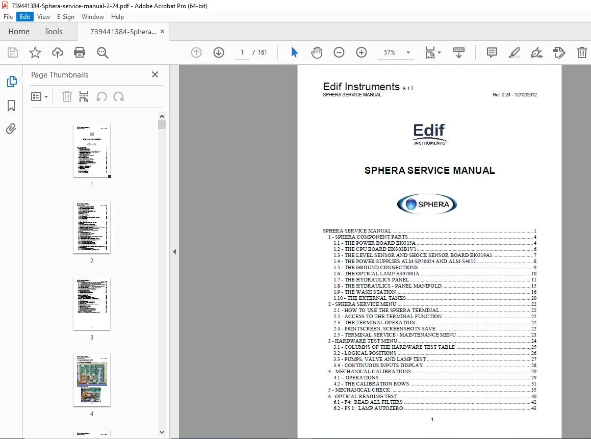
COMPLETE TABLE OF CONTENTS
CHAPTER 1: SPHERA COMPONENT PARTS (Pages 4-21)
1.1 The Power Board EI0315A (Pages 4-5):
- Power board layout
- Wiring connections
- Component identification
- Power distribution
- Connection points
1.2 The CPU Board EI0302B1V1 (Page 6):
- CPU board layout
- Microprocessor system
- Memory organization
- I/O interfaces
- Communication ports
1.3 Level Sensor and Shock Sensor Board EI0319A1 (Page 7):
- Sensor board location
- Level detection circuits
- Shock/collision detection
- Needle protection system
- Signal processing
1.4 Power Supplies ALM-SP50024 and ALM-S4012 (Page 8):
- Power supply specifications
- Voltage outputs
- Installation location
- Replacement procedures
1.5 Ground Connections (Page 9):
- Grounding system
- Ground points
- Shielding connections
- EMI protection
1.6 The Optical Lamp ES07001A (Page 10):
- Lamp specifications
- Lamp housing
- Installation position
- Optical path
- Replacement procedures
1.7 The Hydraulics Panel (Pages 11-14):
- Hydraulics panel layout
- Pump locations
- Valve positions
- Tubing routing
- Component identification
- Manifold connections
1.8 The Hydraulics – Panel Manifold (Page 15):
- Manifold design
- Port connections
- Fluid pathways
- Installation details
1.9 The Wash Station (Pages 16-19):
- Wash station components
- Needle wash well
- Wash mechanism
- Positioning system
- Maintenance access
1.10 The External Tanks (Pages 20-21):
- Reagent tanks
- Waste tanks
- Float sensor systems
- Level detection
- Tank connections
CHAPTER 2: SPHERA SERVICE MENU (Pages 22-23)
2.1 How to Use the Sphera Terminal (Page 22):
- Terminal interface overview
- Navigation methods
- Function keys
- Menu structure
2.2 Access to the Terminal Function (Page 22):
- Service mode access
- Password requirements
- Security features
2.3 The Terminal Operation (Page 22):
- Command entry
- Parameter viewing
- Status monitoring
2.4 PrintScreen, Screenshots Save (Page 22):
- Screen capture function
- Save procedures
- Documentation methods
2.5 Terminal Service/Maintenance Menu (Page 23):
- Main service menu
- Available functions
- Sub-menu access
CHAPTER 3: HARDWARE TEST MENU (Pages 24-28)
3.1 Columns of the Hardware Test Table (Page 25):
- Test table format
- Column definitions
- Status indicators
- Test results interpretation
3.2 Logical Positions (Page 26):
- Component addressing
- Position numbering
- Mechanical references
3.3 Pumps, Valve and Lamp Test (Page 27):
- Individual component testing
- Pump operation verification
- Valve function testing
- Lamp intensity checking
3.4 Continuous Inputs Display (Page 28):
- Real-time input monitoring
- Sensor status
- Analog values
- Digital states
CHAPTER 4: MECHANICAL CALIBRATIONS (Pages 29-34)
4.1 Operations (Pages 29-30):
- Calibration overview
- Calibration sequence
- Required procedures
- Verification methods
4.2 The Calibration Rows (Pages 31-34):
- Sampling arm calibration
- Reaction plate positioning
- Filter wheel calibration
- Wash station positioning
- Needle vertical position
- Reference positions
- Home position verification
CHAPTER 5: MECHANICAL CHECK (Pages 35-39)
- Mechanical system verification
- Movement testing
- Position accuracy
- Belt tension checking
- Alignment verification
- Mechanical integrity assessment
- Operational checks
CHAPTER 6: OPTICAL READING TEST (Pages 40-54)
6.1 F4: Read All Filters (Pages 42):
- Complete filter wheel test
- All wavelength verification
- Optical path testing
6.2 F5 1: Lamp Autozero (Pages 43-44):
- Automatic zero calibration
- Baseline establishment
- Reference measurement
- Zero offset correction
6.3 F5 2: Test Autozero Repeatability (Page 45):
- Repeatability verification
- Statistical analysis
- Stability testing
- Acceptance criteria
6.4 F6: Reaction Plate Reading Offset (Page 46):
- Cuvette reading calibration
- Offset determination
- Position verification
6.5 F6 1: Search Fine Reading Offset (Page 47):
- Precision offset adjustment
- Fine-tuning procedures
- Optimization
6.6 F6 2: Adjust Cuvette Rough Offset (Page 48):
- Coarse offset adjustment
- Initial positioning
- Mechanical alignment
6.7 F7: Filters Wheel Test (Page 49):
- Filter wheel operation
- Position accuracy
- Rotation verification
6.8 F7 1: Test FS Home Repeatability (Page 50):
- Home position testing
- Optical switch verification
- Repeatability assessment
6.9 F7 2: Test Filters Wheel Offset + Peak (Pages 51-52):
- Filter alignment testing
- Peak wavelength verification
- Offset measurement
6.10 F9: Cuvettes Status (Pages 53-54):
- Individual cuvette testing
- Optical quality assessment
- Contamination detection
- Exclusion criteria
CHAPTER 7: WASHINGS (Pages 55-64)
7.1 The Washings Menu (Pages 55-56):
- Washing functions
- Menu navigation
- Wash types
7.2 F2: Execute Washes (Page 57):
- Manual wash initiation
- Wash cycle execution
- Verification procedures
7.3 F5: Special Pumps Tests (Page 58):
- Advanced pump testing
- Diagnostic procedures
7.4 F5 1: Test Pumps (Page 59):
- Individual pump testing
- Flow verification
- Performance assessment
7.5 F5 2: Fill Hydraulic Tubes – The Pumps Self-Test (Pages 60-61):
- Hydraulic system priming
- Air removal
- Line filling procedures
- Self-test sequence
7.6 F5 3: Empty Tubes (Page 62):
- System drainage
- Line clearing
- Maintenance preparation
7.7 F5 4: Check Residue (Pages 62-64):
- Carryover testing
- Contamination assessment
- System cleanliness verification
CHAPTER 8: SYSTEM PARAMETERS (Pages 65-69)
8.1 Edit Parameters (Page 65):
- Parameter access
- Modification procedures
- Value entry
8.2 Parameter Pages (Pages 66-68):
- Parameter organization
- Function categories
- Parameter descriptions
- Default values
- Adjustment ranges
8.3 Save the Parameters List on a Text File (Page 69):
- Parameter backup
- Export procedures
- Documentation methods
CHAPTER 9: ADJUSTMENTS (Pages 70-79)
9.1 A/D Voltage References Adjustment (Page 70):
- Analog-to-digital calibration
- Reference voltage setting
- Accuracy verification
9.2 Reaction Plate Temperature Adjustment (Page 71):
- Temperature calibration
- PID tuning
- Setpoint verification
- Stability testing
9.3 Optical Offset and Gain Adjustment (Pages 72-73):
- Photometric calibration
- Offset correction
- Gain optimization
- Dynamic range setting
9.4 Filter Wheel Adjustment (Page 74):
- Belt tension
- Optical switch alignment
- Offset verification
- Position checking
9.5 Reaction Plate Belt Tightening (Pages 75-76):
- Belt tension adjustment
- Pulley alignment
- Smooth operation verification
9.6 Needle Vertical Adjustment in Wash Well (Page 77):
- Needle height setting
- Wash well clearance
- Position optimization
9.7 Wash Station Down Adjustment (Page 78):
- Wash station lowering
- Position calibration
- Contact verification
9.8 Adjustment of Cover Detection Switch (Page 79):
- Safety switch positioning
- Detection verification
- Interlock testing
CHAPTER 10: SERVICING (Pages 80-113)
10.1 Lamp Replacement (Pages 80-81):
- Lamp removal procedures
- New lamp installation
- Optical alignment
- Verification testing
10.2 Sample Tray Replacement (Pages 82-83):
- Tray removal
- New tray installation
- Position verification
10.3 Single Reaction Cell Replacement (Page 84):
- Individual cuvette replacement
- Installation procedures
- Optical testing
10.4 Reaction Rotor Replacement (Pages 85-87):
- Complete rotor removal
- New rotor installation
- Alignment procedures
- Temperature sensor connection
- Testing and verification
10.5 Needle Replacement (Pages 88-91):
- Needle removal procedures
- New needle installation
- Calibration requirements
- Level sensor connection
- Testing procedures
10.6 Interference Filters Replacement and Equalization (Page 92):
- Filter removal
- New filter installation
- Optical equalization
- Wavelength verification
10.7 Vacuum Pump Replacement (Page 93):
- Pump removal
- New pump installation
- Connection verification
- Performance testing
10.8 Vacuum Pump Membrane Valves Replacement (Pages 94-96):
- Membrane valve service
- Valve replacement
- Reassembly procedures
- Leak testing
10.9 Peristaltic Pump Head Replacement (Page 97):
- Pump head removal
- New head installation
- Tubing routing
- Flow verification
10.10 Diluter Replacement with EE0101A Diluter (Pages 98-100):
- Diluter removal procedures
- New diluter installation
- Calibration requirements
- Performance verification
10.11 Diluter Sealing Gasket Replacement (Page 101):
- Gasket removal
- New gasket installation
- Leak prevention
- Testing
10.12 Sampling Arm Replacement (Page 102):
- Arm removal procedures
- New arm installation
- Calibration requirements
- Movement verification
10.13 Level Sensor Wiring Replacement (Pages 103-105):
- Wiring removal
- New wiring installation
- Connection procedures
- Continuity testing
10.14 External Tanks Floats Replacement (Page 106):
- Float sensor removal
- New sensor installation
- Level detection testing
- Calibration
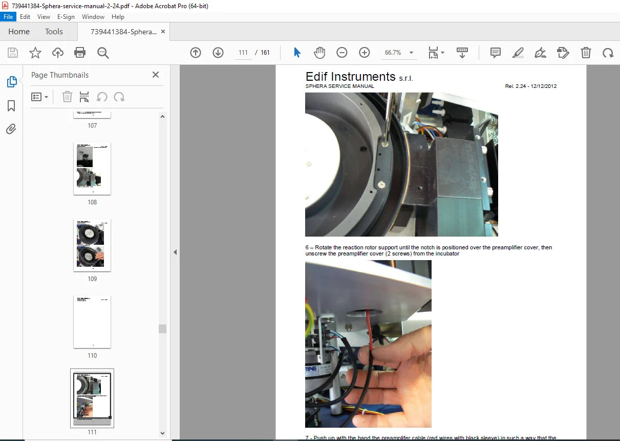
10.15 Optical Preamplifier Replacement (Pages 107-113):
- Preamplifier removal
- New preamplifier installation
- Connection procedures
- Optical calibration
- Gain adjustment
- Testing and verification
CHAPTER 11: FIRMWARE UPDATING – EPROMs REPLACEMENT (Pages 114-115)
11.1 EPROMs Replacement (Page 114):
- EPROM removal procedures
- New EPROM installation
- Firmware version verification
- System initialization
11.2 Replacement of Very Old EPROMs – Data Synchronization (Page 115):
- Legacy system updates
- Data migration
- Parameter preservation
- Compatibility procedures
CHAPTER 12: TROUBLESHOOTING (Pages 116-126)
12.1 The Analyzer Does Not Connect (Pages 116-118):
- Communication problems
- Power supply issues
- Cable verification
- Software problems
- Diagnostic steps
12.2 Optical Readings Have Bad Repeatability (Page 119):
- Lamp instability
- Filter wheel problems
- Optical contamination
- Mechanical vibration
- Electrical noise
12.3 Autozero Has Bad Repeatability, Unstable Optical Signal (Page 120):
- Lamp aging
- Power supply instability
- Optical path contamination
- Preamplifier issues
- Temperature effects
12.4 Reaction Plate Temperature is Uncontrolled (Pages 121-122):
- Temperature sensor failure
- Heater malfunction
- Control circuit problems
- PID parameter issues
- Thermal insulation
12.5 Reaction Cuvettes Become Dirty and Are Excluded Quickly (Pages 123-124):
- Wash station problems
- Inadequate washing
- Reagent contamination
- Protein buildup
- Cleaning procedures
12.6 A Droplet Forms on the Needle Tip (Page 125):
- Vacuum leak
- Needle damage
- Aspiration problems
- Hydraulic issues
12.7 Aberrant or Null Results and Reagent Bottles Wrongly Detected Full (Page 126):
- Level sensor problems
- Float sensor failures
- Wiring issues
- Detection circuit faults
12.8 “Needle Shock Detector is Stuck” Error Message (Page 126):
- Shock sensor malfunction
- Mechanical binding
- Sensor calibration
- Electrical problems
CHAPTER 13: PERIODICAL CHECK-UP, SERVICE PROCEDURE (Pages 127-129)
13.1 Six Months Programmed Maintenance (Pages 127-129):
- Preventive maintenance schedule
- Inspection checklist
- Cleaning procedures
- Lubrication requirements
- Calibration verification
- Performance testing
- Parts replacement schedule
- Documentation requirements
CHAPTER 14: SCHEMATICS AND LAYOUTS (Pages 130-133)
14.1 EI0302 CPU Board Layout (Page 130):
- Component placement diagram
- Board connections
- Test points
14.2 Schematics: Memory and Microprocessor (Page 131):
- CPU circuit diagram
- Memory organization
- Address decoding
- Control signals
14.3 Schematics: Digital INPUT/OUTPUT (Page 132):
- Digital I/O circuits
- Interface circuits
- Buffer circuits
- Protection circuits
14.4 Schematics: Analog Input (Page 133):
- A/D converter circuits
- Signal conditioning
- Input protection
- Reference voltages
APPENDICES
APPENDIX A: SYSTEM PARAMETERS LIST (Pages 134-142):
- Complete parameter listing
- Parameter descriptions
- Default values
- Adjustment ranges
- Function explanations
APPENDIX B: ERROR CODES (Pages 143-147):
B.1 HI Software Error Codes (Pages 143-146):
- Software error listings
- Error descriptions
- Corrective actions
B.2 Firmware Execution Error Codes (Page 147):
- System error codes
- Hardware failures
- Diagnostic codes
APPENDIX C: SPHERA CONSUMABLES AND SPARE PARTS (Pages 148-151):
- Consumables list
- Part numbers
- Replacement intervals
- Spare parts catalog
- Ordering information
APPENDIX D: HI SOFTWARE INSTALLATION/UPDATE 0.40 (Pages 152-154):
D.1 Settings (Page 152):
- Software configuration
- Initial setup
D.2 HI Software Updating – Release 0.40 (Page 152):
- Update procedures
- Version installation
D.3 The HI Data Folder (Page 153):
- Data storage
- Folder structure
- Backup procedures
D.4 Compatibility with Windows Seven (Page 154):
- Operating system compatibility
- Installation notes
D.5 Device Drivers (Page 154):
- Driver installation
- USB communication
- Serial port setup
APPENDIX E: SPHERA ASTM LIS INTERFACE – Software 0.40 (Pages 155-158):
E.1 Sequence of Operations (Page 155):
- LIS communication workflow
- Data exchange
E.2 Features (Page 155):
- LIS capabilities
- Supported functions
E.3 LIS ASTM Worklist Folders (Page 156):
- File management
- Folder structure
E.4 Process Description (Page 156):
- Communication protocol
- Data handling
E.5 ASTM Standard Input Files Encoding (Page 157):
- Input file format
- Data structure
E.6 ASTM Standard Output Files Encoding (Page 157):
- Output file format
- Result reporting
E.7 Example of ASTM Worklist Input File (Page 158):
- Sample file
- Format demonstration
APPENDIX F: MECHANICAL ASSEMBLY (Pages 159-160):
- Assembly diagrams
- Component relationships
- Mechanical layout
APPENDIX G: LIST OF EXTERNAL PDF SERVICE SCHEMATICS (Page 161):
- Additional documentation
- Reference schematics
- External manuals
Who Needs This Manual?
This Edif Sphera service manual is essential for:
- Certified biomedical equipment technicians (CBET)
- Hospital clinical engineering departments
- Edif Instruments authorized service centers
- Medical equipment service companies
- Clinical laboratory technical staff
- Anyone performing authorized service on Sphera analyzers
Prerequisites:
✓ Edif Instruments service training
✓ Clinical chemistry analyzer experience
✓ Electronic troubleshooting skills
✓ Optical system knowledge
✓ Hydraulic/pneumatic system experience
✓ Biomedical equipment service experience
✓ Understanding of clinical chemistry principles
✓ ESD handling procedures
FILE DETAILS
| Detail | Specification |
|---|---|
| Manual Title | Sphera Service Manual |
| Release | 2.24 |
| Publication Date | December 12, 2012 (12/12/2012) |
| Author | Enrico |
| Manufacturer | Edif Instruments s.r.l. |
| Pages | 161 pages |
| PDF Quality | Professional technical manual with detailed diagrams |
| File Size | 11.4 MB |
| Page Size | A4 (595 x 842 pts) |
| Language | English |
| Producer | Bullzip PDF Printer (Freeware Edition) |
| PDF Version | 1.5 |