
ELGI EG Series 11-125 HP Electric Screw Air Compressor Parts Service Manual PDF
Original price was: $95.00.$18.95Current price is: $18.95.
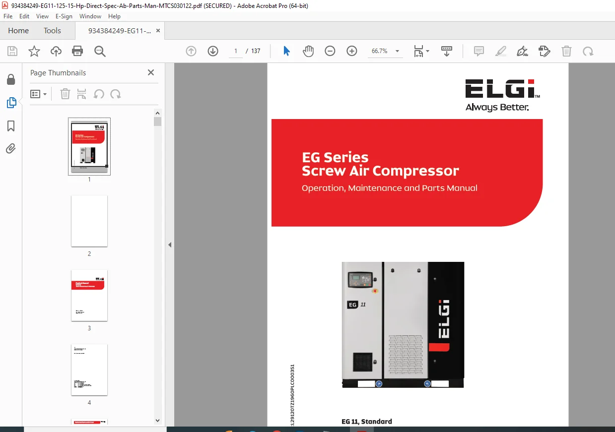
Official ELGI EG Series electric screw air compressor product manual covering models EG 11 through EG 125 (15-125 HP range), 460V, 3-phase, 60Hz, air-cooled configuration. This comprehensive 137-page technical manual includes specifications, installation procedures, operation instructions, maintenance schedules, controller programming, troubleshooting, and complete illustrated parts catalog. Essential reference for industrial air compressor technicians servicing ELGI rotary screw compressors.
Description
ELGI EG Series 11-125 HP Electric Screw Air Compressor Parts Service Manual – PDF DOWNLOAD
DESCRIPTION:
ELGI EG Series Electric Screw Air Compressor – Complete Product Manual
This is the official product manual (Part/Document No. 019000665, Document No. MTCS030122) published by ELGI Equipments Limited for the EG Series Electric Powered Rotary Screw Air Compressors. This comprehensive technical guide provides operators, service technicians, and maintenance personnel with complete specifications, installation procedures, operation instructions, maintenance schedules, troubleshooting, and illustrated parts catalogs for ELGI EG series industrial air compressors.
File Details:
- Manual Name: EG Series Electric Powered Screw Air Compressor Product Manual
- Models Covered: EG 11 – 125.0 (15 HP – 125 HP range)
- Configuration: Air-Cooled, Standard, Direct Drive
- Voltage: 460V, 3-Phase, 60Hz
- Year: Current edition
- Document Number: Part No. 019000665 / MTCS030122
- Manual PDF Quality: Excellent – Factory original with clear diagrams
- Total Pages: 137
MODELS COVERED:
EG Series Electric Screw Air Compressors:
This manual covers the complete EG series range including:
Small to Medium Models:
- EG 11 – 11 kW (15 HP)
- EG 15 – 15 kW (20 HP)
- EG 18 – 18.5 kW (25 HP)
- EG 22 – 22 kW (30 HP)
- EG 30 – 30 kW (40 HP)
- EG 37 – 37 kW (50 HP)
- EG 45 – 45 kW (60 HP)
- EG 55 – 55 kW (75 HP)
Medium to Large Models:
- EG 75 – 75 kW (100 HP)
- EG 90 – 90 kW (125 HP)
- EG 110 – 110 kW (150 HP)
- EG 132 – 132 kW (175 HP)
- EG 160 – 160 kW (215 HP)
- EG 200 – 200 kW (270 HP)
- EG 250 – 250 kW (335 HP)
Configuration Covered:
- Air-Cooled design
- Standard models
- Standard + VFD (Variable Frequency Drive) models
- 460V, 3-Phase, 60Hz (±10% voltage, ±5% frequency)
- Direct drive configuration
- Alternative voltage: 208-230V / 460V
COMPREHENSIVE MANUAL CONTENTS:
CHAPTER 1: ABOUT ELGI
Company information and product overview:
- ELGI Equipments Limited company profile
- Manufacturing capabilities
- Global presence
- Product range overview
- Quality certifications
- Contact information
- Coimbatore, TN – 641 005, India
- Tel: 91-422-2589555
- Regional office contacts
- Warranty information
- Machine identification and sale record
CHAPTER 2: GENERAL FUNCTIONAL DESCRIPTION
Complete system overview:
EG Series Design Features:
- Rotary screw air compressor technology
- Compact and self-contained design
- Direct drive configuration (no belts)
- Air-cooled heat exchanger system
- Integrated control system
- Space-saving footprint
- Industrial-grade construction
- Energy-efficient operation
- Low noise enclosure
- Easy maintenance access
System Components:
- Screw air end (compression element)
- Electric drive motor
- Air inlet filtration system
- Control and regulation system
- Discharge and cooling system
- Lubrication system
- Base frame and canopy
- Control panel with controller
- Safety systems and alarms
CHAPTER 3: GA DRAWING & P&I DIAGRAM
Technical drawings and schematics:
General Arrangement (GA) Drawing:
- Overall dimensions and clearances
- Component locations
- Mounting points
- Service access areas
- Connection points (air, electrical, condensate)
- Installation footprint
- Lifting points for handling
Piping & Instrumentation (P&I) Diagram:
- Complete air flow schematic
- Oil flow circuits
- Cooling system flow paths
- Control system pneumatics
- Pressure sensor locations
- Temperature sensor locations
- Valve locations and functions
- Filter positions
- Separator assembly
CHAPTER 4: TECHNICAL DATA
Complete specifications for all models:
Performance Data by Model:
- Working pressure range (bar.g / psi.g)
- Free Air Delivery (FAD) – m³/min / cfm
- Motor power ratings (kW / HP)
- Full load current draw
- Specific power consumption
- Sound pressure levels (dB)
- Compressed air outlet size
- Condensate drain size
Operating Conditions:
- Ambient temperature range
- Maximum altitude operation
- Humidity considerations
- Air inlet temperature limits
- Cooling air requirements
Physical Specifications:
- Overall dimensions (L x W x H)
- Operating weight
- Shipping weight
- Floor space requirements
- Clearance requirements
Electrical Data:
- Voltage: 208-230V / 460V (±10%)
- Frequency: 60Hz (±5%)
- Phase: 3-phase
- Motor frame sizes (NEMA):
- 254T/L / B35
- 256T / B35
- 284T / B35
- 286T / B35
- Control voltage specifications
- Fan motor ratings:
- 0.38 kW (208-230V) / 0.40 kW (460V)
- Single or dual fan configurations
- Cable sizing requirements
Fluid Capacities:
- Oil sump capacity
- Separator element volume
- Cooler capacity
Environmental Data:
- Operating temperature range
- Storage temperature range
- Maximum relative humidity
- IP protection rating
- Sound pressure level measurements
CHAPTER 5: INSTALLATION AND OPERATION
Complete installation and startup procedures:
Pre-Installation Requirements:
- Site survey and preparation
- Foundation requirements
- Minimum clearance specifications
- Ventilation requirements
- Cooling air flow calculations
- Electrical supply verification
- Piping layout planning
- Condensate management
Installation Procedures:
- Unpacking and inspection
- Positioning and leveling
- Foundation mounting (if required)
- Electrical connections
- Main power supply
- Control circuit wiring
- Grounding requirements
- Cable routing
- Compressed air piping connections
- Condensate drain connections
- Remote start/stop wiring (optional)
Pre-Operation Checks:
- Visual inspection checklist
- Oil level verification
- Electrical connections verification
- Rotation direction check
- Valve position verification
- Safety system testing
Startup Procedures:
- Initial power-up sequence
- Controller initialization
- First start procedures
- Load/unload testing
- Pressure setting adjustment
- Break-in period recommendations
Operating Instructions:
- Control panel overview
- Starting the compressor
- Normal operation monitoring
- Load/unload operation
- Pressure adjustment
- Stopping the compressor
- Emergency shutdown procedures
Operating Modes:
- Manual mode operation
- Automatic start/stop
- Load/unload control
- VFD operation (variable speed models)
- Remote operation
CHAPTER 6: MAINTENANCE
Comprehensive maintenance program:
Maintenance Schedule Overview:
- Daily maintenance tasks
- Weekly maintenance requirements
- 500-hour service intervals
- 2000-hour service intervals
- 4000-hour service intervals
- 8000-hour service intervals
- Annual maintenance requirements
Daily Maintenance:
- Visual inspection checklist
- Check for oil and air leaks
- Drain condensate from separator
- Check oil level in sight glass
- Monitor operating pressure
- Check discharge air temperature
- Verify warning indicators
- Clean external surfaces
Weekly Maintenance:
- Check air inlet filter condition
- Inspect cooling fan operation
- Check belt tension (if applicable)
- Verify condensate drain operation
- Check for abnormal noise or vibration
500 Hour Service:
- Check air inlet filter (replace if needed)
- Check oil filter pressure drop
- Inspect cooler fins for debris
- Check all hose connections
- Verify safety valve operation
- Check electrical connections
- Lubricate motor bearings (if required)
2000 Hour Service:
- Replace air inlet filter element
- Replace oil filter element
- Check minimum pressure valve
- Inspect check valve operation
- Clean oil cooler (if needed)
- Check drive motor condition
- Verify control system operation
4000 Hour Service:
- Replace oil separator element
- Change compressor oil (complete system)
- Clean/replace cooling fan filter
- Inspect all gaskets and seals
- Check motor insulation resistance
- Calibrate pressure sensors
- Test safety systems
- Clean entire cooling system
8000 Hour Service:
- Major service inspection
- Screw element inspection
- Motor bearing service/replacement
- Complete electrical system inspection
- Pressure vessel inspection
- Valve rebuild/replacement
- Controller firmware update check
- Complete system performance test
Lubrication System Maintenance:
- Oil specifications (biodegradable options available)
- Oil level checking procedures
- Oil change procedures
- Oil filter replacement
- Oil cooler cleaning
- Oil separator service
- System flushing procedures
Air System Maintenance:
- Air filter service
- Inlet valve cleaning
- Minimum pressure valve service
- Check valve maintenance
- Safety valve testing
- Discharge piping inspection
CHAPTER 7: CONTROLLER
Control system programming and operation:
Controller Features:
- Digital control interface
- LCD display with menu navigation
- Real-time parameter monitoring
- Alarm history logging
- Service interval tracking
- Multi-language support
- Password protection
- Communication protocols
Display Information:
- Operating pressure
- Discharge temperature
- Motor running hours
- Loaded hours
- Service countdown timers
- Fault codes and alarms
- System status indicators
Menu Navigation:
- Operating parameters display
- Setpoint adjustments
- Configuration menus
- Service menus
- Alarm history
- System information
- Communication settings
Parameter Settings:
- Load/unload pressure setpoints
- Pressure differential settings
- Temperature limits
- Time delay settings
- VFD parameters (variable speed models)
- Start/stop sequence timing
- Warning and alarm thresholds
Programming Procedures:
- Access levels and passwords
- Pressure adjustment
- Timer settings
- Alarm configuration
- Service interval programming
- Language selection
- Display customization
Alarm and Warning System:
- High temperature shutdown
- High pressure shutdown
- Low oil pressure warning
- Service due indicators
- Emergency stop activation
- Phase failure protection
- Motor overload protection
- Separator differential pressure alarm
Troubleshooting Controller Issues:
- Display problems
- Communication errors
- Sensor faults
- Password recovery
- Reset procedures
- Diagnostic mode access
CHAPTER 8: AIR INLET AND CONTROL SYSTEM
Inlet system components and service:
Air Inlet Filter:
- Filter element specifications
- Filter housing design
- Service indicator operation
- Filter replacement procedures
- Differential pressure monitoring
- Filter sizing and selection
Inlet Valve Assembly:
- Valve construction and operation
- Load/unload control function
- Pneumatic actuation system
- Adjustment procedures
- Troubleshooting inlet valve issues
- Seal replacement
- Valve rebuild procedures
Control System Components:
- Pressure sensors/transducers
- Temperature sensors
- Solenoid valves
- Pilot air system
- Control lines and fittings
- Pressure switches
- Safety interlocks
Service Procedures:
- Inlet filter replacement
- Inlet valve cleaning
- Sensor calibration
- Solenoid valve testing
- Control line inspection
- Leak detection and repair
CHAPTER 9: DRIVE SYSTEM
Motor and drive components:
Electric Motor Specifications:
- NEMA frame sizes by model
- Horsepower ratings
- Voltage and current specifications
- Efficiency class
- Service factor
- Insulation class
- Protection rating (IP rating)
- Mounting configuration (B35 flange)
Direct Drive Design:
- Coupling assembly
- Alignment specifications
- Shaft connection
- No belt maintenance required
- Reduced energy loss
- Compact design advantages
Motor Protection:
- Thermal overload protection
- Phase failure protection
- Under/over voltage protection
- Motor starter specifications
- Contactor ratings
Service Procedures:
- Motor inspection
- Bearing lubrication (if required)
- Insulation resistance testing
- Coupling inspection
- Alignment verification
- Connection tightness check
CHAPTER 10: DISCHARGE SYSTEM
Air discharge path and components:
Compression Element (Air End):
- Screw compressor design
- Male and female rotors
- Housing construction
- Bearing systems
- Shaft seals
- Capacity control mechanism
Oil Separator System:
- Separator vessel design
- Separator element function
- Oil return system
- Scavenging line
- Pressure differential monitoring
- Separator element replacement
Minimum Pressure Valve:
- Valve function and operation
- Opening pressure specification
- Maintenance procedures
- Troubleshooting
Check Valve:
- Prevents reverse flow
- Valve construction
- Service procedures
- Seal replacement
Discharge Piping:
- Outlet connection size
- Aftercooler (if equipped)
- Moisture separator
- Air receiver connection
- Piping materials and sizing
CHAPTER 11: COOLING SYSTEM
Heat removal and cooling:
Air-Cooled Design:
- Fan cooling system
- Fan motor specifications
- Single fan: 0.38 kW (208-230V) / 0.40 kW (460V)
- Dual fan: 0.38 kW (208-230V) / 0.40 kW (460V) x 2
- Fan rotation speed: 1560 RPM (208-230V) / 1630 RPM (460V)
- Airflow requirements
- Cooling fan control
Heat Exchanger:
- Oil cooler design
- Air-to-oil heat transfer
- Fin construction
- Cleaning procedures
- Efficiency monitoring
Cooling Circuit:
- Oil temperature control
- Thermostatic valve operation
- Temperature sensor locations
- Cooling system flow path
Maintenance Procedures:
- Cooler cleaning (external fins)
- Internal cleaning procedures
- Fan inspection and service
- Temperature sensor calibration
- Thermostatic valve testing
Troubleshooting:
- High temperature alarms
- Insufficient cooling
- Fan motor problems
- Cooler blockage
- Thermostatic valve failure
CHAPTER 12: LUBRICATION SYSTEM
Oil circulation and filtration:
Oil System Components:
- Oil reservoir/sump
- Oil filter assembly
- Oil cooler
- Oil separator
- Oil injection points
- Oil return lines
- Sight glass
- Oil drain valve
Oil Specifications:
- Recommended oil types
- Viscosity requirements
- Biodegradable oil options available
- Oil capacity by model
- Oil change intervals
- Synthetic vs. mineral oil
Oil Filter:
- Filter element specifications
- Bypass valve operation
- Filter replacement procedures
- Differential pressure monitoring
- Filter housing service
Oil Separator:
- Separator element function
- Oil coalescing process
- Element replacement timing
- Differential pressure monitoring
- Separator efficiency
Oil Level Management:
- Sight glass reading
- Proper oil level
- Adding oil procedures
- Oil consumption monitoring
Oil Change Procedures:
- Complete oil drain
- Filter replacement
- Separator replacement (if due)
- System refilling
- Oil level verification
- Break-in procedures after oil change
CHAPTER 13: BASE AND CANOPY SYSTEM
Structural components:
Base Frame:
- Heavy-duty steel construction
- Vibration isolation
- Mounting provisions
- Lifting points
- Component mounting
- Condensate drainage
Canopy/Enclosure:
- Sound attenuation design
- Access panels and doors
- Ventilation openings
- Weather protection
- Control panel integration
- Safety interlocks on panels
Service Access:
- Removable panels
- Easy component access
- Tool-less panel removal
- Maintenance friendly design
- Clear component labeling
CHAPTER 14: SPARE KIT DETAILS
Comprehensive spare parts information:
Standard Spare Kits:
500 Hour Service Kit:
- Air inlet filter element
- Oil filter element (if due)
- Gaskets and seals
- Service labels
2000 Hour Service Kit:
- Air inlet filter element
- Oil filter element
- Minor service gaskets
- O-rings
- Service documentation
4000 Hour Service Kit:
- Air inlet filter element
- Oil filter element
- Oil separator element
- Complete oil change kit
- Cooling fan filter (if equipped)
- Gasket set
- O-ring set
- Drain valve kit
- Service labels and tags
8000 Hour Service Kit:
- Major overhaul components
- Bearing sets
- Seal kits
- Valve rebuild kits
- Complete gasket set
- Wear parts
Individual Spare Parts:
- Filter elements by part number
- Separator elements by model
- Valve kits and components
- Sensor and switch assemblies
- Electrical components
- Hoses and fittings
- Lubricants and fluids
- Mounting hardware
Parts Ordering Information:
- Part numbers for each model
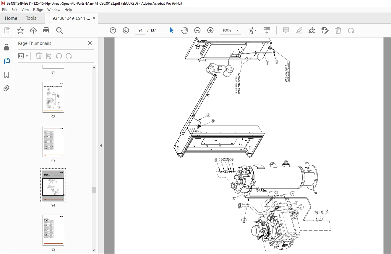
- Exploded view diagrams
- Assembly illustrations
- Quantity requirements
- Cross-reference charts
- Recommended stock items
KEY FEATURES OF ELGI EG SERIES:
Design Advantages: ✓ Direct Drive – No belts to adjust or replace
✓ Compact Design – Space-saving footprint
✓ Air-Cooled – No water cooling infrastructure required
✓ Energy Efficient – Low specific power consumption
✓ Low Noise – Sound-attenuated enclosure
✓ Easy Maintenance – Service-friendly design
✓ Reliable Operation – Industrial-grade components
Control Features: ✓ Digital Controller – Advanced monitoring and control
✓ Load/Unload Control – Automatic pressure regulation
✓ VFD Option – Variable speed for ultimate efficiency
✓ Remote Monitoring – Communication capability
✓ Service Tracking – Automatic maintenance alerts
✓ Alarm History – Fault logging and diagnostics
Safety Systems: ✓ High Temperature Shutdown – Protects equipment
✓ High Pressure Safety – Prevents overpressure
✓ Motor Protection – Overload and phase monitoring
✓ Emergency Stop – Quick shutdown capability
✓ Safety Valve – Pressure relief protection
Who Needs This Manual:
✓ Industrial Air Compressor Technicians servicing ELGI equipment
✓ Plant Maintenance Engineers managing compressed air systems
✓ Facilities Maintenance Teams with ELGI compressors
✓ Compressor Distributors providing service and support
✓ Manufacturing Facilities with in-house maintenance programs
✓ Service Companies maintaining industrial air systems
✓ Equipment Operators requiring detailed technical information
✓ Maintenance Managers planning preventive maintenance
✓ Technical Training Centers educating compressor technicians
✓ Parts Specialists ordering correct replacement components
What Makes This Manual Essential:
- Official ELGI factory documentation – Authorized technical information
- Complete model range coverage – EG 11 through EG 250 (15-335 HP)
- 137 comprehensive pages – Full technical documentation
- Detailed GA drawings and P&I diagrams – Complete schematics
- Maintenance schedules – All service intervals covered
- Controller programming guide – Setup and configuration
- Troubleshooting procedures – Systematic diagnostics
- Complete parts catalog – Spare kit details with part numbers
- Installation instructions – Proper setup procedures
- Technical specifications – All models detailed
Critical Applications:
Industries Using ELGI Compressors:
- Manufacturing and production
- Automotive facilities
- Food and beverage processing
- Pharmaceutical manufacturing
- Electronics assembly
- Textile production
- Woodworking operations
- Plastics manufacturing
- Chemical processing
- General industrial applications
Compressed Air Uses:
- Pneumatic tools and equipment
- Process air requirements
- Control air systems
- Spray painting operations
- Material handling
- Packaging machinery
- Assembly operations
- Product testing
- Clean room applications
- Instrumentation air
ELGI Quality and Support:
ELGI Equipments Limited:
- Leading global air compressor manufacturer
- ISO certified quality systems
- Engineering excellence from India
- Global service network
- Technical support availability
- Genuine spare parts supply
- Warranty program
- Training and education
Contact Information:
- Headquarters: Coimbatore, Tamil Nadu, India
- Regional offices worldwide
- 24/7 technical support
- Online parts ordering
Professional industrial air compressor service resource! This official ELGI EG Series product manual is absolutely essential for anyone operating, maintaining, or servicing ELGI rotary screw air compressors from 15 HP to 125 HP. Download instantly and access complete technical specifications, detailed maintenance schedules, controller programming procedures, troubleshooting guides, and comprehensive parts catalogs with ordering information. Keep your industrial compressed air system running efficiently with factory-authorized service procedures, proper maintenance intervals, and genuine ELGI spare parts identification. Perfect for plant maintenance teams, service technicians, and facilities managers requiring professional-grade technical documentation for reliable compressed air production!
Pricing Rationale:
- Official ELGI factory product manual (137 pages)
- Covers complete EG series range (15-125 HP models in this edition)
- Industrial rotary screw air compressor equipment
- Complete technical specifications and maintenance schedules
- Detailed parts catalog with ordering information
- Controller programming and troubleshooting guides
- Target audience: industrial maintenance technicians, plant engineers
- Essential for preventive maintenance programs
- Supports multiple compressor models in one manual
- Professional industrial equipment documentation pricing
- Critical for reducing downtime and ensuring proper service