eMachines E630 E430 Service Manual – Complete Repair Guide PDF Download
Original price was: $95.00.$18.95Current price is: $18.95.
Official eMachines E630/E430 series laptop service manual with complete disassembly procedures, troubleshooting guides, BIOS configuration, and FRU replacement instructions. This comprehensive 198-page technical guide includes step-by-step illustrated teardown procedures, component locations, diagnostic flowcharts, POST codes, and complete parts lists. Essential for laptop technicians servicing eMachines 15.6″ and 17″ notebook computers with AMD processors.
Description
eMachines E630 E430 Service Manual – Complete Repair Guide PDF Download
FILE DETAILS
| Specification | Details |
|---|---|
| Manual Name | eMachines E630/E430 Series Service Guide |
| Models Covered | E630 Series (15.6″ LCD), E430 Series (17″ LCD) |
| Equipment Type | Consumer Laptop / Notebook Computer |
| Processor Support | AMD Sempron, Athlon 64 X2, Athlon 64, Turion |
| Publication Date | December 2009 |
| Pages | 198 Pages |
| File Format | |
| File Size | 8.8 MB |
| Quality | Factory Original with High-Quality Diagrams |
| Publisher | ©2009 eMachines Incorporated |
| OS Support | Windows 7 |
FULL DESCRIPTION
Official eMachines E630/E430 Series Service Manual
This is the complete factory-authorized eMachines E630 service manual PDF for professional laptop technicians and repair specialists. This comprehensive E430 laptop repair guide download provides detailed step-by-step disassembly procedures, troubleshooting diagnostics, BIOS configuration, and complete FRU (Field Replaceable Unit) parts lists for the eMachines E630 and E430 notebook series.
LAPTOP SPECIFICATIONS COVERED
Models:
- eMachines E630 Series – 15.6″ LCD Display
- eMachines E430 Series – 17″ LCD Display
Platform & Processors:
- AMD Sempron™ Single-Core Processor
- AMD Athlon™ 64 X2 Dual-Core Processor
- AMD Athlon™ 64 Single-Core Processor
- AMD Turion™ Dual-Core Processor
- AMD Tigris RS880M + SB710 Chipset
Display Options:
- 15.6″ LCD with CCFL/LED Backlight
- 17″ LED Backlight Display
- ATI Radeon™ HD 4200 Graphics
- UMA VGA Memory (up to 128MB shared)
Memory:
- DDR2 SDRAM Controller (up to 333 MHz)
- 128-bit Low-Latency, High-Bandwidth
- 2 SO-DIMM Slots (DDR2 667/800)
- Maximum: 4GB Total (2GB per slot)
- Up to 1MB On-Board Cache
Storage & Optical:
- 2.5″ SATA Hard Disk Drive
- DVD-Super Multi Double-Layer Drive
- Multi-in-1 Card Reader (SD, MMC, MS, MS PRO, xD)
Connectivity:
- 802.11b/g/n WLAN/WiMax
- Atheros AR8132L 10/100 LAN
- 2x USB 2.0 Ports
- VGA Port (15-pin)
- RJ-45 Ethernet Port
- External USB 2.0 Modem Support
Audio:
- Realtek ALC272X-GR High Definition Audio
- Dolby Digital Live Support
- Internal Speakers x2 (2W each)
- Mic-In and Headphone/Line-Out Jacks
Power:
- 48.8W 4400mAh Lithium-Ion Battery
- 3-Pin 65W AC Adapter
- ACPI 3.0 Compliant
- ENERGY STAR Certified
COMPREHENSIVE CHAPTER BREAKDOWN
CHAPTER 1 – SYSTEM SPECIFICATIONS
Features & Overview (Pages 1-3)
- Complete feature list and capabilities
- Operating system support (Windows 7)
- Platform specifications
- System memory configuration
- Display options and graphics
- Storage subsystem details
- Audio capabilities
- Dimensions and weight
- Communication features
- Privacy and security controls
- Power subsystem specifications
- Keyboard and special keys
- I/O interface ports
- Environmental operating conditions
System Block Diagram (Page 4)
- Complete chipset architecture
- Component interconnections
- Bus structure and data flow
Your eMachines Notebook Tour (Pages 5-11)
- Front View – Display, keyboard, touchpad identification
- Closed Front View – Status indicators, card reader
- Rear View – Port locations
- Left View – Connectivity ports
- Right View – Optical drive, additional ports
- Bottom View – Access panels, battery, cooling vents
- LED Indicators – Power, battery, HDD, Num Lock, Caps Lock
- TouchPad Basics – Touchpad operation and gestures
Using the Keyboard (Pages 12-15)
- Lock keys and embedded numeric keypad
- Windows keys functionality
- Hot key combinations
- Special key functions
- Fn key shortcuts
Hardware Specifications and Configurations (Pages 16-22)
- Detailed component specifications
- Configuration options by model
- Memory configurations
- Storage options
- Wireless module specifications
CHAPTER 2 – SYSTEM UTILITIES
BIOS Setup Utility (Pages 23-30)
- Navigating the BIOS utility interface
- Information Tab – System information display
- Main Tab – Basic system configuration
- System time and date
- Boot device priority
- Hard drive configuration
- Optical drive settings
- Security Tab – Password configuration
- Supervisor password
- User password
- HDD password protection
- Password on boot settings
- Boot Tab – Boot sequence configuration
- Boot priority order
- Boot options
- Network boot settings
- Exit Tab – Save and exit options
BIOS Flash Utilities (Pages 31-33)
- DOS Flash Utility
- Creating bootable DOS disk
- BIOS flashing procedure
- Safety precautions
- WinFlash Utility
- Windows-based BIOS update
- Step-by-step flashing instructions
- Verification procedures
Remove HDD/BIOS Password Utilities (Pages 34-38)
- Password removal procedures
- Security bypass methods for authorized service
- Password recovery utilities
CHAPTER 3 – MACHINE DISASSEMBLY AND REPLACEMENT
Disassembly Requirements (Pages 39-40)
- Required tools and equipment
- Pre-disassembly safety instructions
- ESD precautions
- Workspace preparation
- General disassembly guidelines
External Module Disassembly (Pages 41-51)
- External Modules Disassembly Flowchart
- Battery Pack Removal – Release latches, removal procedure
- SD Dummy Card Removal – Card slot access
- Lower Covers Removal – Access panel removal
- Optical Drive Module – ODD release and removal
- DIMM Modules – Memory slot access and RAM removal
- WLAN Module – Wireless card removal procedure
- Hard Disk Drive Module – HDD bracket and drive removal
Main Unit Disassembly (Pages 52-76)
- Main Unit Disassembly Flowchart
- Switch Cover Removal – Power button bezel removal
- Keyboard Removal – Keyboard release and cable disconnection
- LCD Module Removal – Complete display assembly removal
- Hinge screw removal
- Cable disconnection
- LCD separation from base
- Upper Cover Removal – Palmrest and top case removal
- Screw locations
- Snap fitting release
- Cable routing
- Power Board Removal – DC jack board removal
- Speaker Module Removal
- Left speaker removal
- Right speaker removal
- Speaker cable routing
- TouchPad Bracket Removal – Touchpad assembly removal
- Mainboard Removal – Motherboard extraction
- Cable disconnection sequence
- Screw locations
- Component clearance
- RTC Battery Removal – CMOS battery replacement
- Thermal Module Removal – Heatsink and cooling assembly
- CPU Fan Removal – Cooling fan extraction
- CPU Removal – Processor socket release and removal
LCD Module Disassembly (Pages 77-86)
- LCD Module Disassembly Flowchart
- LCD Bezel Removal – Front display trim removal
- Camera Module Removal – Webcam extraction
- LCD Panel Removal – Display panel separation
- Screw locations
- Video cable disconnection
- LCD Brackets and FPC Cable – Mounting bracket removal
- Antenna Removal – WLAN antenna cable routing
LCD Module Reassembly (Pages 87-94)
- Antenna Replacement – Proper cable routing and adhesion
- LCD Panel Replacement – Display installation
- Camera Module Replacement – Webcam installation
- LCD Bezel Replacement – Bezel snap-fitting
Main Module Reassembly (Pages 95-117)
- CPU Replacement – Processor installation and thermal paste
- CPU Fan Replacement – Fan mounting
- Thermal Module Replacement – Heatsink installation
- Mainboard Replacement – Motherboard installation sequence
- TouchPad Bracket Replacement
- Speaker Module Replacement (Left and Right)
- Power Board Replacement
- Upper Cover Replacement – Palmrest installation
- LCD Module Replacement – Display assembly installation
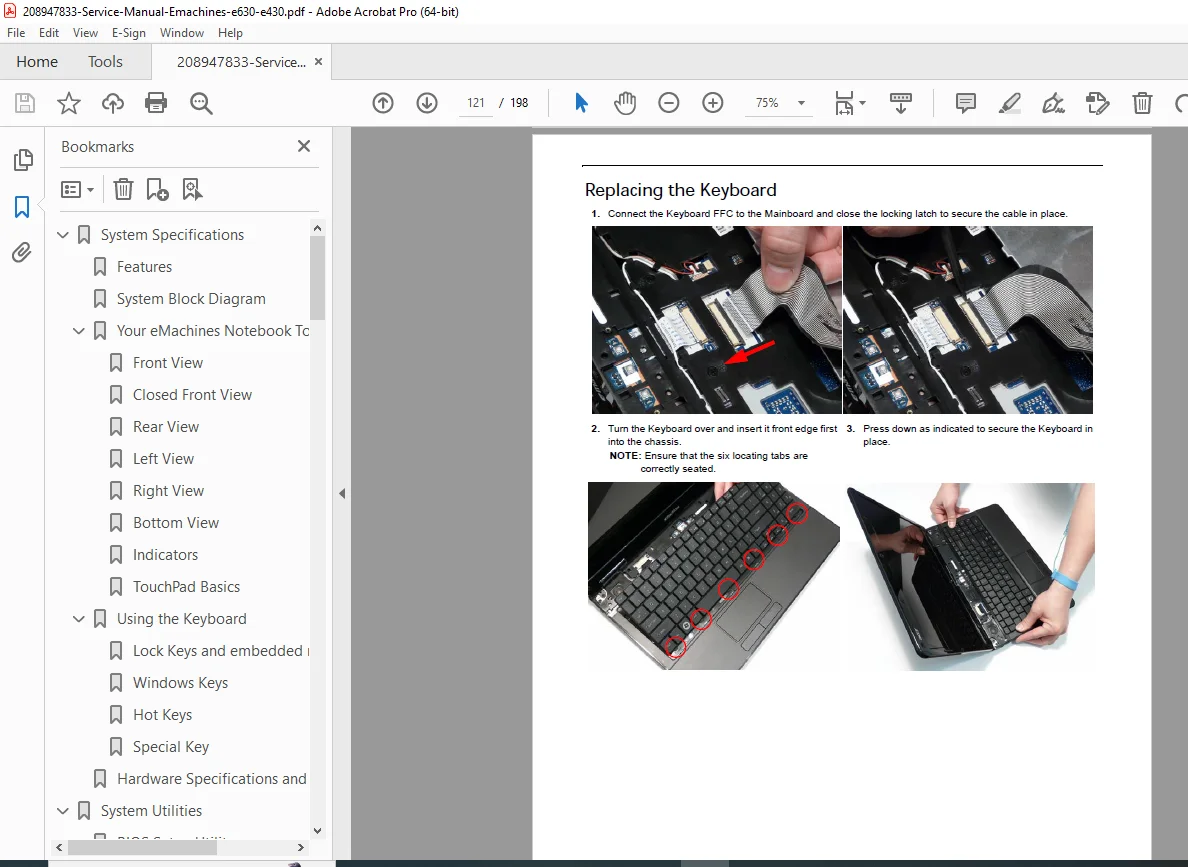
- Keyboard Replacement – Keyboard cable connection
- Switch Cover Replacement
- Hard Disk Drive Module Replacement
- WLAN Module Replacement
- DIMM Modules Replacement
- ODD Module Replacement
- Lower Covers Replacement
- SD Dummy Card Replacement
- Battery Replacement
CHAPTER 4 – TROUBLESHOOTING
Common Problems (Pages 119-131) Comprehensive diagnostic procedures for:
- Power On Issues (Page 120)
- No power symptoms
- Power LED behavior
- AC adapter testing
- Battery testing
- Power button failure
- No Display Issues (Page 121)
- Black screen diagnostics
- External monitor testing
- Video cable inspection
- LCD panel testing
- Inverter board testing
- Random Loss of BIOS Settings (Page 122)
- CMOS battery testing
- RTC circuit diagnostics
- BIOS chip verification
- LCD Failure (Page 123)
- Backlight issues
- Dead pixels
- Dim display
- Flickering screen
- Lines or artifacts
- Built-In Keyboard Failure (Page 123)
- Key not responding
- Multiple keys failure
- Keyboard cable testing
- Connector inspection
- TouchPad Failure (Page 124)
- Cursor not moving
- Erratic behavior
- Buttons not working
- Touchpad cable testing
- Internal Speaker Failure (Page 124)
- No audio output
- Distorted sound
- One speaker not working
- Audio codec testing
- HDD Not Operating Correctly (Page 126)
- Not detected in BIOS
- Slow performance
- Clicking noises
- Boot failure
- SMART errors
- ODD Failure (Page 127)
- Disc not reading
- Tray not opening
- Burning failures
- Drive not detected
- Wireless Function Failure (Page 130)
- WLAN not detected
- Cannot connect to network
- Weak signal
- Antenna testing
- Thermal Unit Failure (Page 130)
- Overheating symptoms
- Fan not spinning
- Excessive noise
- Thermal shutdown
- External Mouse Failure (Page 131)
- USB port testing
- Mouse driver issues
- Other Failures (Page 131)
- Card reader issues
- Port failures
- Audio jack problems
Intermittent Problems (Page 132)
- Diagnostic procedures for sporadic issues
- Environmental factor testing
- Thermal cycling tests
Undetermined Problems (Page 132)
- Systematic diagnostic approach
- Component isolation testing
- Process of elimination
POST Codes (Pages 133-140)
- SEC (Security) POST Codes
- Memory POST Codes
- Memory initialization
- Memory sizing
- Memory testing
- BDS & Specific Action POST Codes
- Boot device selection
- Driver initialization
- Hardware enumeration
- Driver Entry Point Codes
- Device driver loading sequence
- 80_PORT diagnostic codes
- SmmDriver Entry Point Codes
- System Management Mode initialization
CHAPTER 5 – JUMPER AND CONNECTOR LOCATIONS
Mainboard Connector Reference (Pages 141-143)
- Top View Connector Map
- All connector locations labeled
- Function descriptions
- Pin-out references
- Bottom View Connector Map
- Underside connector locations
- Component identifiers
- Power Board Connectors
- DC-IN connector
- Battery connector
- Power distribution
Clearing Password Check and BIOS Recovery (Pages 144-146)
- Password Clearing Procedures
- Hardware method
- Jumper locations
- Clear CMOS Jumper
- Jumper location
- Procedure for CMOS reset
- Default BIOS settings restoration
- BIOS Recovery by Crisis Disk
- Creating recovery media
- Crisis recovery procedure
- Emergency BIOS flash
CHAPTER 6 – FRU (FIELD REPLACEABLE UNIT) LIST
E630/E430 Exploded Diagrams (Pages 148-151)
- Main Assembly Diagram
- Top-level component identification
- Screw locations and types
- Base Assembly Diagram
- Bottom case components
- Internal layout
- Rear Assembly Diagram
- I/O port assembly
- Hinge components
E630/E430 FRU Part Numbers (Pages 152-161) Complete parts catalog including:
- Mainboard assemblies (various configurations)
- LCD panels (15.6″ and 17″ options)
- Keyboards (various languages)
- Memory modules
- Hard drives
- Optical drives
- Wireless modules
- AC adapters
- Batteries
- Speakers
- Cables and connectors
- Covers and bezels
- Screws and fasteners
- Thermal modules
- Fans
- All field-replaceable components
CHAPTER 7 – MODEL DEFINITION AND CONFIGURATION
Model Variants (Pages 162-176)
- Complete model number breakdown
- Configuration matrices
- Regional variations
- Feature differences by SKU
- Memory configuration options
- Display options
- Storage configurations
- Wireless options
- Processor options
CHAPTER 8 – TEST COMPATIBLE COMPONENTS
Windows 7 Environment Test (Pages 177-182)
- Tested and certified components
- Compatible memory modules
- Compatible hard drives
- Compatible optical drives
- Compatible wireless cards
- Driver compatibility
- Upgrade component recommendations
CHAPTER 9 – ONLINE SUPPORT INFORMATION
Service Resources (Page 183)
- eMachines/CSD web support
- Downloads and updates
- Service guide updates
- Driver downloads
- BIOS updates
- Support contact information
KEY FEATURES OF THIS SERVICE MANUAL
✓ 198 Pages of Detailed Procedures – Comprehensive laptop service documentation
✓ Step-by-Step Illustrated Disassembly – Photo-illustrated teardown procedures
✓ Complete Troubleshooting Section – Diagnostic flowcharts and solutions
✓ BIOS Configuration Guide – Complete BIOS setup documentation
✓ FRU Parts List – Complete part numbers for ordering
✓ POST Code Reference – Diagnostic code interpretation
✓ Exploded View Diagrams – Component location and assembly
✓ Reassembly Procedures – Proper component installation
✓ Password Recovery Tools – BIOS and HDD password removal
✓ Component Testing – Systematic diagnostic procedures
✓ Connector Locations – Mainboard and cable reference
IDEAL FOR:
- Laptop Repair Technicians
- Computer Service Centers
- IT Support Professionals
- Electronics Repair Shops
- Technical Schools and Training Centers
- eMachines Authorized Service Providers
- Independent Laptop Repair Specialists
- DIY Enthusiasts and Advanced Users
- Refurbishment Companies
- Corporate IT Departments
WHY THIS MANUAL IS ESSENTIAL:
This eMachines notebook disassembly instructions manual is the authoritative reference for servicing E630 and E430 series laptops. With detailed photo-illustrated procedures for every disassembly step, technicians can confidently perform component replacements without damaging fragile plastic clips or ribbon cables. The comprehensive troubleshooting section provides systematic diagnostic approaches for common laptop failures, from power issues to display problems.
The FRU parts list ensures you order the correct replacement components, while the BIOS section provides essential configuration information for system setup and password management. POST code references help diagnose boot failures quickly, and the connector location diagrams prevent confusion when reconnecting cables during reassembly.
💻 INSTANT DOWNLOAD – PROFESSIONAL LAPTOP REPAIR STARTS NOW! This is the exact same eMachines E630 service manual PDF used by authorized eMachines service centers worldwide. With 198 pages of factory-quality technical documentation, you’ll have immediate access to complete disassembly procedures, troubleshooting diagnostics, BIOS configuration guides, and FRU part numbers that will save hours of diagnostic time and prevent costly repair mistakes. Stop struggling with incomplete information or risking component damage during disassembly – download this official manual now and service eMachines E630/E430 laptops with factory-level expertise!
Pricing Rationale:
- 198 pages of comprehensive service documentation
- Official eMachines factory publication
- Covers two laptop series (E630 and E430)
- Detailed photo-illustrated disassembly procedures
- Complete troubleshooting and diagnostic section
- FRU parts list with part numbers
- BIOS configuration and password recovery
- POST code reference for diagnostics
- Consumer laptop market with moderate pricing
- Essential for laptop repair technicians and service centers
- Competitive pricing for laptop service manuals
- High utility for ongoing repair and maintenance work