Trusted Business
Verified & Licensed
Virus Free Files
100% Safe Downloads
Secure Payment
SSL Protected
Instant Delivery
Available Immediately
Sale!
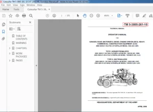
CAT Track-Type Tractor D6T Electrical Schematic Manual PDF
Original price was: $78.00.$19.95Current price is: $19.95.
EN CAT Track-Type Tractor D6T Track-Type Tractor Electrical System Schematic Manual – PDF DOWNLOAD
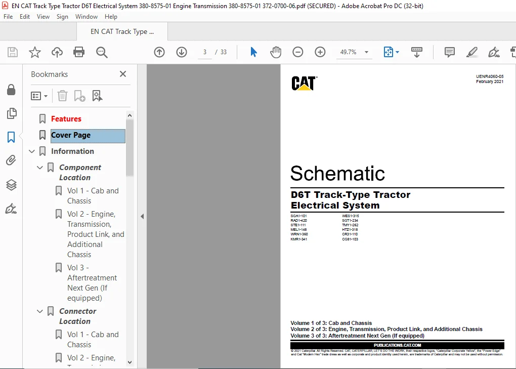
SGA1-101 WES1-315
CG81-103
CR31-110
HTZ1-318
TMY1-262
SGT1-234
KMR1-341
WRN1-360
MEL1-148
STE1-111
RAD1-420
Instant PDF Download
Available immediately
Save to Your Device
Download & keep forever
Antivirus Scanned
100% virus-free
Trusted Worldwide
175,000+ customers
Description
EN CAT Track-Type Tractor D6T Track-Type Tractor Electrical System Schematic Manual – PDF DOWNLOAD
FILE DETAILS:
EN CAT Track-Type Tractor D6T Track-Type Tractor Electrical System Schematic Manual – PDF DOWNLOAD
Language : English
Pages : 33
Downloadable : Yes
File Type : PDF
Size:6.31 MB

SGA1-101 WES1-315
CG81-103
CR31-110
HTZ1-318
TMY1-262
SGT1-234
KMR1-341
WRN1-360
MEL1-148
STE1-111
RAD1-420
TABLE OF CONTENTS:
EN CAT Track-Type Tractor D6T Track-Type Tractor Electrical System Schematic Manual – PDF DOWNLOAD
Features...................................................................... 1
Cover Page.................................................................... 3
Information................................................................... 0
	Component Location........................................................ 0
		Vol 1 - Cab and Chassis............................................... 4
		Vol 2 - Engine, Transmission, Product Link, and Additional Chassis.... 5
		Vol 3 - Aftertreatment Next Gen (If equipped)......................... 6
	Connector Location........................................................ 0
		Vol 1 - Cab and Chassis............................................... 7
		Vol 2 - Engine, Transmission, Product Link, and Additional Chassis.... 8
		Vol 3 - Aftertreatment Next Gen (If equipped)......................... 9
Schematics.................................................................... 0
	Function Isolation Tools.................................................. 0
		Grids On/Off.......................................................... 0
		All Circuits Off...................................................... 0
		All Circuits On....................................................... 0
	Vol 1 - Cab and Chassis...................................................10
		Unspecified Circuit................................................... 0
		Black (Ground)........................................................ 0
		032 (Red) (Battery Power)............................................. 0
		640 (Blue) (Key Power)................................................ 0
		305 (Lt Blue) (Converter Output Circuit).............................. 0
		021 (Orange) (Starting)............................................... 0
		258 (Dk Purple) (Power Train Control Circuit)......................... 0
		509 (Lt Pink) (Engine Control Circuit)................................ 0
		613 (Dk Yellow) (Heat/AC)............................................. 0
		4665 (Tan) (Turn/Wiper/Washer)........................................ 0
		CON 509 (J1939/1587 D.L.)............................................. 0
		SUB 141 (Lt Orange) (Impl/Valve/Tool Control Circuit)................. 0
		CON 190 (CAN "A" D.L.)................................................ 0
		CON 522 (CAN "B" D.L.)................................................ 0
		CON 141 (CAN "C" D.L.)................................................ 0
		CON 305 (CAN "D" D.L.)................................................ 0
		CON 5767 (Olive Green) (DEF).......................................... 0
		SUB 522 (Lt Purple) (Aftertreatment).................................. 0
		SUB 651 (Blue Gray) (Ethernet)........................................ 0
	Vol 2 - Engine, Transmission, Product Link, and Additional Chassis........11
		Unspecified Circuit................................................... 0
		Black (Ground)........................................................ 0
		032 (Red) (Battery Power)............................................. 0
		640 (Blue) (Key Power)................................................ 0
		021 (Orange) (Starting)............................................... 0
		190 (Dk Pink) (Start Aid)............................................. 0
		258 (Dk Purple) (Transmission Control Circuit)........................ 0
		509 (Lt Pink) (Engine Control Circuit)................................ 0
		613 (Dk Yellow) (Heat/AC)............................................. 0
		CON 509 (J1939/1587 D.L.)............................................. 0
		CON 032 (RS232/485 D.L.).............................................. 0
		SUB 141 (Lt Orange) (Impl/Valve/Tool Control Circuit)................. 0
		CON 190 (CAN "A" D.L.)................................................ 0
		CON 522 (CAN "B" D.L.)................................................ 0
		CON 141 (CAN "C" D.L.)................................................ 0
		CON 5767 (Olive Green) (DEF).......................................... 0
		SUB 522 (Lt Purple) (Aftertreatment).................................. 0
		SUB 651 (Blue Gray) (Ethernet)........................................ 0
	Vol 3 - Aftertreatment Next Gen (If equipped).............................12
		Unspecified Circuit (0.51)............................................ 0
		Black (Ground)........................................................ 0
		032 (Red) (Battery Power)............................................. 0
		640 (Blue) (Key Power)................................................ 0
		CON 509 (J1939/1587 D.L.)............................................. 0
		CON 141 (CAN "C" D.L.)................................................ 0
		CON 5767 (Olive Green) (DEF).......................................... 0
		SUB 522 (Lt Purple) (Aftertreatment).................................. 0
Machine Views................................................................. 0
	Vol 1 - Cab and Chassis................................................... 0
		Dash View.............................................................13
		Headliner View........................................................14
		LH Exterior Cab View..................................................15
		LH Fender View........................................................16
		LH Interior Cab View..................................................17
		Radiator Guard View...................................................18
		Rear Chassis View.....................................................19
		RH Console View.......................................................20
		ROPS View.............................................................21
	Vol 2 - Engine, Transmission, Product Link, and Additional Chassis........ 0
		Aftertreatment........................................................22
		Hood View.............................................................23
		Implement Valve Configurations........................................24
		LH Engine View........................................................25
		LH Fender View........................................................26
		Product Link..........................................................27
		Pump Tank Unit........................................................28
		Radiator View.........................................................29
		RH Engine View........................................................30
		Transmission..........................................................31
		WAVS..................................................................32
	Vol 3 - Aftertreatment Next Gen (If equipped)............................. 0
		Pump Tank Unit........................................................33
IMAGES PREVIEW OF THE MANUAL:
PLEASE NOTE:
- This is the SAME manual used by the dealers to troubleshoot any faults in your vehicle. This can be yours in 2 minutes after the payment is made.
- Contact us at [email protected] should you have any queries before your purchase or that you need any other service / repair / parts operators manual.
S.M