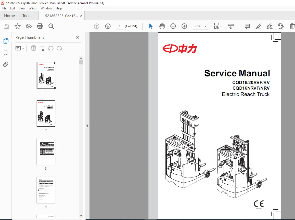
EP CQD16 CQD20 RVF RV Service Manual PDF Electric Reach Truck Forklift Repair – PDF
Original price was: $85.00.$15.95Current price is: $15.95.
Official EP Equipment service manual for CQD16/20RVF/RV and CQD16NRVF/NRV electric reach trucks (SM-3316 07.16, July 2016). This comprehensive 251-page technical manual covers 1,600-2,000kg capacity reach forklifts with maintenance schedules, chassis/drive/hydraulic/electrical system service, AC2 controller diagnostics, EPS-AC0 steering controller, pump motor repair, multi-way solenoid valve service, mast assembly procedures, cylinder maintenance, wiring diagrams, error codes, and complete troubleshooting for warehouse equipment technicians.
Description
EP CQD16 CQD20 RVF RV Service Manual PDF Electric Reach Truck Forklift Repair – PDF DOWNLOAD
DESCRIPTION
This is the official EP Equipment Service Manual (Document SM-3316 07.16, July 2016) for CQD16/20RVF/RV and CQD16NRVF/NRV electric reach truck forklifts. This comprehensive 251-page technical manual provides complete maintenance, troubleshooting, repair, and service procedures for qualified forklift technicians to maintain these electric reach trucks used in warehouses, distribution centers, manufacturing facilities, and logistics operations worldwide.
Product Overview
EP Equipment CQD Electric Reach Trucks:
The CQD series represents EP Equipment’s advanced electric reach truck lineup designed for narrow-aisle warehouse operations, high-level order picking, and intensive material handling applications. These sophisticated forklifts combine AC drive technology, electronic power steering, advanced hydraulic systems, and comprehensive safety features to deliver efficient and reliable performance in demanding warehouse environments.
Key Applications:
- Warehouse storage and retrieval
- Narrow aisle operation
- High-level order picking
- Distribution center operations
- Manufacturing facility logistics
- Cold storage operations
- Retail distribution centers
- Third-party logistics (3PL)
- Cross-docking operations
- Pallet handling and stacking
Models Covered
CQD16RV:
- Capacity: 1,600 kg (3,527 lbs)
- Full Height Series
- Medium Configuration
- Manual valve hydraulics
CQD16NRV:
- Capacity: 1,600 kg (3,527 lbs)
- Full Height Series
- Medium Configuration
- Narrow Body design
- Manual valve hydraulics
CQD16RVF:
- Capacity: 1,600 kg (3,527 lbs)
- Full Height Series
- Premium Configuration
- Solenoid valve hydraulics
- Advanced controls
CQD16NRVF:
- Capacity: 1,600 kg (3,527 lbs)
- Full Height Series
- Premium Configuration
- Narrow Body design
- Solenoid valve hydraulics
CQD20RV:
- Capacity: 2,000 kg (4,409 lbs)
- Full Height Series
- Medium Configuration
- Manual valve hydraulics
CQD20RVF:
- Capacity: 2,000 kg (4,409 lbs)
- Full Height Series
- Premium Configuration
- Solenoid valve hydraulics
Key Technical Systems
Drive System:
- AC traction motor
- AC2 traction controller
- Electromagnetic brakes
- Gearbox with reduction drive
- Drive wheel assembly
- Proximity switch sensors
Steering System:
- Electric power steering (EPS)
- EPS-AC0 controller
- AC steering motor
- Power-assisted control
Hydraulic System:
Premium Models (RVF/NRVF):
- AC pump motor
- AC2 pump controller
- Gear pump
- Multi-way solenoid valve
- Solenoid valve controller
- Electronic hydraulic control
- Reach cylinder
- Lift cylinders
- Tilt cylinders
Medium Models (RV/NRV):
- AC pump motor
- Gear pump
- Multi-way manual valve
- Manual hydraulic control
- Reach cylinder
- Lift cylinders
- Tilt cylinders
Electrical System:
- Battery power system
- Main contactor
- DC-DC converter
- Multiple controllers (AC2, EPS-AC0, SICOS)
- Digital instrument cluster
- Height display (RVF/NRVF)
- Control switches
- Handheld diagnostic unit (optional)
Control System:
- Accelerator pedal
- Brake pedal
- Travel switch
- Emergency stop switch
- Key switch
- Control lever
- Rocker switch
- Foot switch
- Stepper motor
Mast Systems:
- Two-stage mast
- Three-stage mast (≤7.5m height)
- Three-stage mast (8.0-9.5m height)
- Three-stage mast (10-11m height)
- Lifting chains
- Fork carriage
- Built-in side shifter (optional)
Comprehensive Manual Contents
DOCUMENT INFORMATION:
- Title: Service Manual CQD16/20RVF/RV, CQD16NRVF/NRV
- Document Number: SM-3316 07.16
- Release Date: July 7, 2016
- Version: 07.16
- Manufacturer: EP Equipment Co., Ltd.
- Location: Anji County, Zhejiang Province, China
- Pages: 251 pages
- Copyright: EP Equipment Co., Ltd.
FOREWORD AND SAFETY
Manual Purpose:
- System component information
- Maintenance procedures
- Troubleshooting guidance
- Technical specifications
Safety Instructions:
- ⚠ Safety signs for personal injury prevention
- ℹ Important safety instructions
- Proper operation requirements
- Maintenance safety precautions
Copyright Notice:
- Copyright belongs to EP Equipment Co., Ltd.
- All rights reserved
- Contact: 400-0550-205
COMPLETE TABLE OF CONTENTS
SECTION 1: INFORMATION & SPECIFICATIONS (Pages 1-8)
1.1 After-sales Service Platform (Page 3):
- Service contact information
- Support resources
- Dealer network
1.2 Introduction (Page 4):
- Manual overview
- Model identification
- Safety information
1.3 Common Tools (Page 5):
- Required service tools
- Special tools
- Test equipment
1.4 General Tightening Torques (Pages 6-8):
- Standard bolt torques
- Thread size specifications
- Torque values
- Fastener grades
SECTION 2: MAINTENANCE (Pages 9-20)
2.1 Overview (Page 11):
- Maintenance importance
- Service intervals
- Safety precautions
2.2 Maintenance (Pages 12-20):
2.2.1 Cleaning (Page 12):
- Cleaning procedures
- Approved cleaning agents
- Component cleaning
- Electrical system cleaning
2.2.2 Inspection (Pages 12-16):
- Daily inspection checklist
- Weekly inspection
- Monthly inspection
- Annual inspection
- Component condition assessment
- Wear limits
- Safety system checks
2.2.3 Lubrication (Pages 17-20):
- Lubrication points
- Lubricant specifications
- Lubrication intervals
- Grease fittings
- Oil change procedures
- Hydraulic oil specifications
SECTION 3: STRUCTURE & FUNCTIONS (Pages 21-30)
3.1 Structure & Functions (Pages 23-30):
Complete component descriptions including:
- 3.1.1 Travel Switch
- 3.1.2 Emergency Stop Switch
- 3.1.3 Key Switch
- 3.1.4 Horn Button
- 3.1.5 Control Switch (RVF/NRVF)
- 3.1.6 Control Switch (RV/NRV)
- 3.1.7 Instrument
- 3.1.8 Horn
- 3.1.9 Fan
- 3.1.10 Accelerator Pedal
- 3.1.11 Brake Pedal
- 3.1.12 Foot Switch
- 3.1.13 Warning Light
- 3.1.14 Headlight
- 3.1.15 Rocker Switch
- 3.1.16 Stepper Motor
- 3.1.17 AC2 Controller (Traction Controller)
- 3.1.18 AC2 Controller (Pump Controller)
- 3.1.19 EPS-AC0 Controller
- 3.1.20 DC-DC Converter
- 3.1.21 Main Contactor
- 3.1.22 Solenoid Valve Controller (RVF/NRVF)
- 3.1.23 Multi-way Solenoid Valve (RVF/NRVF)
- 3.1.24 Multi-way Manual Valve (RV/NRV)
- 3.1.25 Pump Motor
- 3.1.26 Gear Pump
SECTION 4: CHASSIS SYSTEM (Pages 31-38)
4.1 Load Wheel (Page 33):
- Removal and installation
- Faults and causes
- Bearing service
4.2 Caster (Page 34):
- Removal and installation
- Caster maintenance
4.3 Brake Pedal (Pages 35-36):
- Removal and installation
- Faults and causes
- Adjustment procedures
4.4 Seat (Page 36):
- Removal and installation
- Seat adjustment
4.5 Brakes (Pages 37-38):
- Removal and installation
- Faults and causes
- Brake inspection
- Adjustment procedures
SECTION 5: DRIVE SYSTEM (Pages 39-54)
5.1 Drive Wheel (Page 42):
- Removal and installation
- Faults and causes
- Wheel maintenance
5.2 Electromagnetic Brakes (Pages 43-45):
- Removal and installation
- Faults and causes
- Checking and testing
- Control circuit troubleshooting
- Brake adjustment
5.3 Drive Motor (Pages 46-48):
- Removal and installation
- Faults and causes
- Checking and testing
- Control circuit troubleshooting
- AC motor diagnostics
5.4 Gearbox (Page 49):
- Removal and installation
- Faults and causes
- Gearbox service
5.5 Proximity Switch (Pages 50-51):
- Removal and installation
- Faults and causes
- Checking and testing
- Control circuit troubleshooting
5.6 Steering Motor (Pages 52-54):
- Removal and installation
- Faults and causes
- Checking and testing
- Control circuit troubleshooting
- EPS diagnostics
SECTION 6: OPERATING SYSTEM (Pages 55-70)
6.1 Control Lever (Page 57):
- Control lever operation
- Adjustment procedures
6.2 Control Panel (Page 57):
- Control panel layout
- Switch functions
6.3 Horn Button (Page 58):
- Removal and installation
- Faults and causes
- Checking and testing
- Control circuit troubleshooting
6.4 Control Switch (RVF/NRVF) (Pages 59-61):
- Removal and installation
- Faults and causes
- Checking and testing
- Control circuit troubleshooting
- Electronic control operation
6.5 Control Switch (RV/NRV) (Pages 62-64):
- Removal and installation
- Faults and causes
- Connection mode
- Checking and testing
- Control circuit troubleshooting
6.6 Stepper Motor (Page 65):
- Removal and installation
- Faults and causes
- Checking and testing
- Control circuit troubleshooting
6.7 Key Switch (Page 66):
- Removal and installation
- Faults and causes
- Checking and testing
- Control circuit troubleshooting
6.8 Emergency Switch (Page 67):
- Removal and installation
- Faults and causes
- Checking and testing
- Control circuit troubleshooting
6.9 Rocker Switch (Pages 68-69):
- Removal and installation
- Faults and causes
- Checking and testing
- Control circuit troubleshooting
6.10 Travel Switch (Page 70):
- Removal and installation
- Faults and causes
- Checking and testing
- Control circuit troubleshooting
SECTION 7: HYDRAULIC SYSTEM (Pages 71-92)
7.1 Overview (Pages 73-75):
- 7.1.1 Hydraulic Schematic Diagram RVF/NRVF
- 7.1.2 Hydraulic Schematic Diagram RV/NRV
- System operation
- Component identification
7.2 Hydraulic Power Unit (Page 76):
- Removal and installation
- System service
7.3 Pump Motor (Pages 76-78):
- Removal and installation
- Faults and causes
- Checking and testing
- Control circuit troubleshooting
- AC motor diagnostics
7.4 Multi-way Reversing Solenoid Valve (RVF/NRVF) (Pages 79-80):
- Removal and installation
- Interface description
- Faults and causes
- Checking and testing
- Control circuit troubleshooting
7.5 Solenoid Valve (RVF/NRVF) (Pages 81-82):
- Faults and causes
- Checking and testing
- Control circuit troubleshooting
- Valve diagnostics
7.6 Multi-way Reversing Manual Valve (RV/NRV) (Pages 83-84):
- Removal and installation
- Interface description
- Faults and causes
- Checking and testing
- Manual valve operation
7.7 Gear Pump (Page 85):
- Removal and installation
- Faults and causes
- Checking and testing
- Pump maintenance
7.8 Reach Cylinder (Pages 86-89):
- Cylinder removal precautions
- Cylinder installation precautions
- Removal and installation
- Cylinder maintenance
- Seal replacement
- Cylinder testing
7.9 Hydraulic Troubleshooting (Page 90):
- Systematic troubleshooting
- Pressure testing
- Flow testing
- Leak detection
7.10 Hydraulic Symbols (Pages 91-92):
- Symbol legend
- Component symbols
- Valve symbols
- Cylinder symbols
SECTION 8: ELECTRICAL SYSTEM (Pages 93-164)
8.1 Controller (Pages 95-106):
- Removal and installation
- 8.1.2 Controller Interface Functions:
- AC2 traction controller interfaces
- AC2 pump controller interfaces
- EPS-AC0 steering controller interfaces
- SICOS controller interfaces
- Solenoid valve controller interfaces
- Pin configurations
- Connection diagrams
- Programming parameters
8.2 Fuse (Pages 107-108):
- Location of fuses
- Fuse ratings
- Checking and testing
- Replacement procedures
8.3 Main Contactor (Pages 109-110):
- Removal and installation
- Faults and causes
- Checking and testing
- Control circuit troubleshooting
8.4 Height Display (RVF/NRVF) (Pages 111-112):
- Removal and installation
- Faults and causes
- Checking and testing
- Control circuit troubleshooting
8.5 Limit Switch (Pages 113-115):
- Removal and installation
- Connection mode
- Faults and causes
- Checking and testing
- Control circuit troubleshooting
8.6 Accelerator Pedal (Pages 116-117):
- Removal and installation
- Faults and causes
- Checking and testing
- Control circuit troubleshooting
- Potentiometer testing
8.7 Foot Switch (Pages 118-119):
- Removal and installation
- Faults and causes
- Checking and testing
- Control circuit troubleshooting
8.8 DC-DC Converter (Page 120):
- Removal and installation
- Faults and causes
- Checking and testing
- Control circuit troubleshooting
- Voltage testing
8.9 Warning Light / Headlight (Page 121):
- Removal and installation
- Faults and causes
- Checking and testing
- Control circuit troubleshooting
8.10 Cooling Fan (Pages 122-123):
- Removal and installation
- Faults and causes
- Checking and testing
- Control circuit troubleshooting
8.11 Seat Switch (Page 124):
- Removal and installation
- Faults and causes
- Checking and testing
- Control circuit troubleshooting
- Safety interlock
8.12 Instrument (Pages 125-128):
- 8.12.1 Instrument Operation Schematics
- Display functions
- Indicator lights
- Warning displays
- Hour meter
- Battery discharge indicator
8.13 Handheld Unit (Optional) (Pages 129-132):
- 8.13.1 Handheld Unit Connection
- 8.13.2 Handheld Unit Menu Options
- 8.13.3 TESTER Menu
- Diagnostic functions
- Parameter viewing
- System testing
8.14 Controller Error Messages (Pages 133-148):
8.14.1 Traction/Pump Controller (Pages 133-137):
- Error code listings
- Error descriptions
- Diagnostic procedures
- Corrective actions
8.14.2 Steering Controller (EPS-AC0) (Pages 138-146):
- Error code listings
- EPS diagnostics
- Troubleshooting procedures
8.14.3 SICOS Controller (Page 147):
- Error codes
- System diagnostics
8.14.4 Solenoid Valve Controller (Page 148):
- Error codes
- Valve diagnostics
8.15 Electrical Schematic Diagrams RVF/NRVF (Pages 149-154):
- Complete 6-page electrical schematic
- Power distribution
- Control circuits
- Safety circuits
- Component connections
8.16 Electrical Schematic Diagrams RV/NRV (Pages 155-159):
- Complete 5-page electrical schematic
- Power distribution
- Control circuits
- Component connections
8.17 Cable Wiring Diagrams (RVF/NRVF) (Page 160):
- Harness routing
- Cable identification
- Connection points
8.18 Cable Wiring Diagrams (RV/NRV) (Page 161):
- Harness routing
- Cable identification
8.19 Wiring Harness and Connectors (RVF/NRVF) (Page 162):
- Connector types
- Pin configurations
- Wire colors
8.20 Wiring Harness and Connectors (RV/NRV) (Page 163):
- Connector types
- Pin configurations
SECTION 9: TROUBLESHOOTING (Pages 165-174)
9.1 Preparation Before Troubleshooting (Page 167):
- 9.1.1 Check Battery Voltage
- Pre-diagnostic checks
- Safety precautions
9.2 Troubleshooting Solutions of Common Faults (Pages 168-174):
- Symptom-based troubleshooting
- No power conditions
- Drive system problems
- Hydraulic system issues
- Steering problems
- Control system faults
- Error code interpretation
APPENDIX A: SERVICE MANUAL – MAST (Pages 175-251)
A1 Two-stage Mast (Pages 177-185):
- Removal and installation
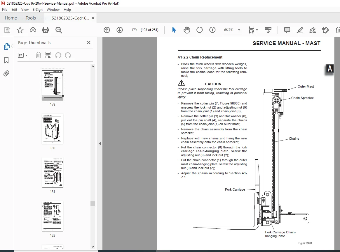
- Lifting chains (adjustment and replacement)
- Mast tubing
- Lift cylinder service
- Tilt cylinder service
- Built-in side shifter
A2 Three-stage Mast (Lifting Height ≤7.5m) (Pages 186-198):
- Removal and installation
- Chain systems (mast and fork carriage)
- Mast tubing maintenance
- Lift cylinder service
- Tilt cylinder service
- Side shifter service
A3 Three-stage Mast (8.0m ≤ Lifting Height ≤ 9.5m) (Pages 199-211):
- High-lift mast service
- Chain maintenance
- Cylinder service
- Mast assembly procedures
A4 Three-stage Mast (10m ≤ Lifting Height ≤ 11m) (Pages 212-251):
- Extra-high-lift mast service
- Chain systems
- Hydraulic cylinder maintenance
- Safety procedures
Who Needs This Manual?
This EP Equipment CQD service manual is essential for:
- EP Equipment authorized service technicians
- Warehouse equipment maintenance teams
- Forklift service companies
- Material handling equipment technicians
- Facility maintenance departments
- Fleet maintenance operations
- Anyone performing authorized service on CQD reach trucks
Prerequisites:
✓ Forklift repair experience
✓ Electric forklift system knowledge
✓ AC motor and controller diagnostics
✓ Hydraulic system experience
✓ Electrical troubleshooting skills
✓ Understanding of material handling equipment
✓ Proper tools and test equipment
✓ Safety training for powered industrial trucks
FILE DETAILS
| Detail | Specification |
|---|---|
| Manual Title | Service Manual CQD16/20RVF/RV, CQD16NRVF/NRV Electric Reach Truck |
| Document Number | SM-3316 07.16 |
| Release Date | July 7, 2016 |
| Version | 07.16 |
| Models Covered | CQD16RV, CQD16NRV, CQD16RVF, CQD16NRVF, CQD20RV, CQD20RVF |
| Capacity Range | 1,600 kg – 2,000 kg |
| Manufacturer | EP Equipment Co., Ltd., China |
| Pages | 251 pages |
| PDF Quality | Professional technical manual with detailed diagrams |
| File Size | 9.8 MB |
| Page Size | A4 (595.22 x 842 pts) |
| Language | English |
| Author | thinkpad |
| PDF Version | 1.5 |