
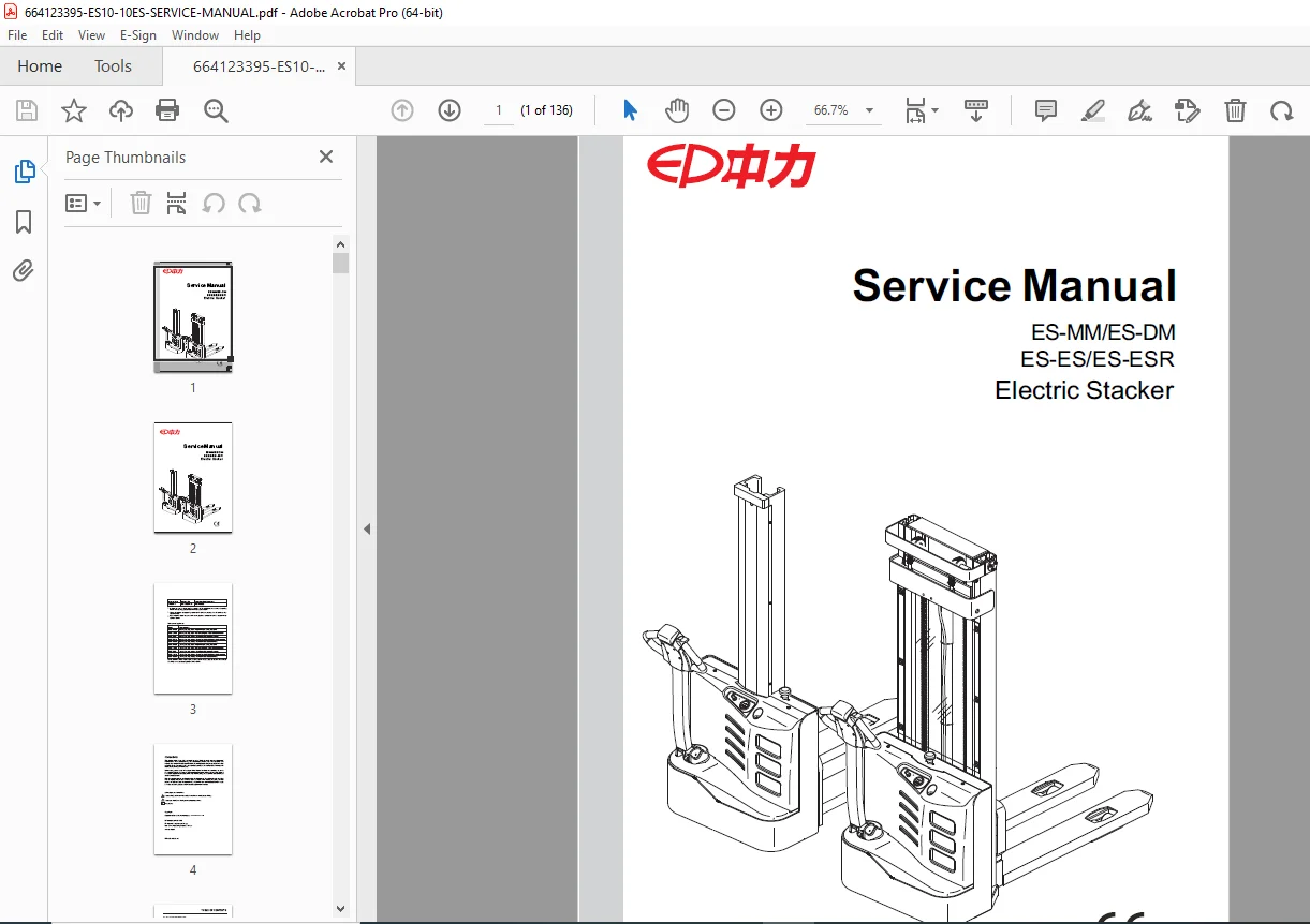
EP ES10-10ES Electric Stacker Service Manual PDF
Original price was: $95.00.$20.95Current price is: $20.95.
Download the official EP ES10-10ES service manual PDF for detailed repair and maintenance of electric stackers. This 136-page guide covers EP ES10 electric stacker service manual PDF download essentials, ES10-10ES hydraulic system troubleshooting guide, two-stage mast maintenance instructions, drive system repair manual PDF, electrical system schematic diagrams, and lead-acid battery care and maintenance PDF. Ideal for technicians handling EP stacker models like ES10-10MM and ES12-12ESR.
Description
EP ES10-10ES Electric Stacker Service Manual PDF DOWNLOAD
Description:
The EP ES10-10ES Electric Stacker Service Manual PDF is a crucial resource for warehouse technicians and equipment maintainers working with EP’s range of pedestrian and standing electric stackers. This comprehensive manual provides step-by-step instructions on troubleshooting, repairs, maintenance, and electrical schematics for models with mono mast and 2-stage mast configurations. Whether you’re searching for EP ES10 electric stacker service manual PDF download, ES10-10ES hydraulic system troubleshooting guide, two-stage mast maintenance instructions, drive system repair manual PDF, electrical system schematic diagrams, or lead-acid battery care and maintenance PDF, this guide ensures efficient diagnostics and upkeep to minimize downtime.
Table of Contents:
- 1. INFORMATION & SPECIFICATIONS (Page 1)
- 1.1 After-sales Service Platform (Page 3)
- 1.2 Introduction (Page 4)
- 1.3 Common Tools (Page 5)
- 1.4 General Tightening Torques (Page 6)
- 2. MAINTENANCE (Page 9)
- 2.1 Overview (Page 11)
- 2.2 Maintenance (Page 12)
- 2.2.1 Cleaning (Page 12)
- 2.2.2 Inspection (Page 12)
- 2.2.3 Lubrication (Page 16)
- 3. STRUCTURE & FUNCTIONS (Page 19)
- 3.1 Structure & Functions (Page 21)
- 3.1.1 Travel Switch (Page 21)
- 3.1.2 Lifting/Lowering Switch (Page 21)
- 3.1.3 Emergency Reverse Switch (Page 21)
- 3.1.4 Horn Switch (Page 21)
- 3.1.5 Emergency Stop Switch (Page 22)
- 3.1.6 Key Switch (Page 22)
- 3.1.7 Charge Gauge (Page 22)
- 3.1.8 Charging Indicator (Page 22)
- 3.1.9 Buzzer (Page 23)
- 3.1.10 Fuse (Page 23)
- 3.1.11 Controller (Page 23)
- 3.1.12 Charger (Page 23)
- 3.1.13 Lifting Limit Switch (Page 24)
- 3.1.14 Interlock Switch (Page 24)
- 3.1.15 Pump Motor (Page 24)
- 3.1.16 Gear Pump (Page 24)
- 3.1.17 Pump Contactor (Page 25)
- 3.1.18 Solenoid Valve (Page 25)
- 3.1 Structure & Functions (Page 21)
- 4. CHASSIS SYSTEM (Page 27)
- 4.1 Load Wheel (Page 29)
- 4.1.1 Removal and Installation (Page 29)
- 4.1.2 Faults and Causes (Page 30)
- 4.2 Cover (Page 30)
- 4.2.1 Removal and Installation (Page 30)
- 4.3 Caster (Page 31)
- 4.3.1 Removal and Installation (Page 31)
- 4.1 Load Wheel (Page 29)
- 5. DRIVE SYSTEM (Page 33)
- 5.1 Drive Assembly (Page 36)
- 5.1.1 Removal and Installation (Page 36)
- 5.2 Electromagnetic Brakes (Page 36)
- 5.2.1 Removal and Installation (Page 37)
- 5.2.2 Faults and Causes (Page 37)
- 5.2.3 Checking and Testing (Page 38)
- 5.2.4 Control Circuit Troubleshooting (Page 39)
- 5.3 Drive Wheel (Page 40)
- 5.3.1 Removal and Installation (Page 40)
- 5.3.2 Faults and Causes (Page 40)
- 5.4 Drive Motor (Page 41)
- 5.4.1 Removal and Installation (Page 41)
- 5.4.2 Faults and Causes (Page 41)
- 5.4.3 Checking and Testing (Page 42)
- 5.5 Gearbox (Page 43)
- 5.5.1 Removal and Installation (Page 43)
- 5.5.2 Faults and Causes (Page 43)
- 5.1 Drive Assembly (Page 36)
- 6. OPERATING SYSTEM (Page 45)
- 6.1 Control Lever (Page 47)
- 6.2 Button Switch (Page 47)
- 6.2.1 Removal and Installation (Page 47)
- 6.2.2 Faults and Causes (Page 48)
- 6.2.3 Checking and Testing (Page 48)
- 6.2.4 Control Circuit Troubleshooting (Page 49)
- 6.3 Travel Switch (Page 51)
- 6.3.1 Removal and Installation (Page 51)
- 6.3.2 Faults and Causes (Page 51)
- 6.3.3 Checking and Testing (Page 51)
- 6.3.4 Control Circuit Troubleshooting (Page 52)
- 7. HYDRAULIC SYSTEM (Page 53)
- 7.1 Overview (Page 55)
- 7.1.1 Hydraulic Schematic Diagram (Page 56)
- 7.2 Pump and Motor Assembly (Page 57)
- 7.2.1 Removal and Installation (Page 57)
- 7.2.2 Component (Page 58)
- 7.3 Pump Motor (Page 58)
- 7.3.1 Removal and Installation (Page 58)
- 7.3.2 Faults and Causes (Page 59)
- 7.3.3 Checking and Testing (Page 59)
- 7.4 Pump Contactor (Page 60)
- 7.4.1 Faults and Causes (Page 60)
- 7.4.2 Checking and Testing (Page 61)
- 7.4.3 Control Circuit Troubleshooting (Page 61)
- 7.5 Solenoid Valve (Page 62)
- 7.5.1 Faults and Causes (Page 62)
- 7.5.2 Checking and Testing (Page 62)
- 7.5.3 Control Circuit Troubleshooting (Page 63)
- 7.6 Reach Cylinder (Page 64)
- 7.6.1 Cylinder Removal Precautions (Page 64)
- 7.6.2 Cylinder Installation Precautions (Page 65)
- 7.7 Hydraulic Troubleshooting (Page 66)
- 7.8 Hydraulic Symbol (Page 67)
- 7.1 Overview (Page 55)
- 8. ELECTRICAL SYSTEM (Page 69)
- 8.1 Controller (Page 71)
- 8.1.1 Removal and Installation (Page 71)
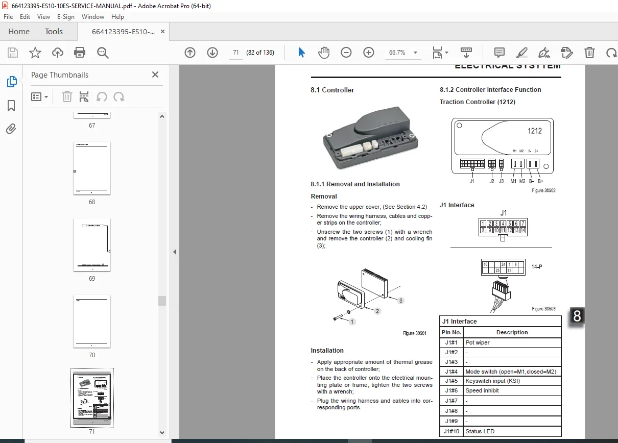
- 8.1.2 Controller Interface Function (Page 71)
- 8.2 Fuse (Page 73)
- 8.2.1 Location of Fuses (Page 73)
- 8.2.2 Checking and Testing (Page 74)
- 8.3 Key Switch (Page 75)
- 8.3.1 Removal and Installation (Page 75)
- 8.3.2 Faults and Causes (Page 75)
- 8.3.3 Checking and Testing (Page 75)
- 8.3.4 Control Circuit Troubleshooting (Page 75)
- 8.4 Charge Gauge (Page 76)
- 8.4.1 Removal and Installation (Page 76)
- 8.4.2 Faults and Causes (Page 76)
- 8.4.3 Checking and Testing (Page 76)
- 8.4.4 Control Circuit Troubleshooting (Page 76)
- 8.5 LED Charging Indicator (Page 77)
- 8.5.1 Removal and Installation (Page 77)
- 8.5.2 Faults and Causes (Page 77)
- 8.5.3 Checking and Testing (Page 77)
- 8.5.4 Control Circuit Troubleshooting (Page 77)
- 8.6 Limit Switch (Page 78)
- 8.6.1 Removal and Installation (Page 78)
- 8.6.2 Connection Mode (Page 78)
- 8.6.3 Faults and Causes (Page 79)
- 8.6.4 Checking and Testing (Page 79)
- 8.6.5 Control Circuit Troubleshooting (Page 79)
- 8.7 Interlock Switch (Page 80)
- 8.7.1 Removal and Installation (Page 80)
- 8.7.2 Faults and Causes (Page 80)
- 8.7.3 Checking and Testing (Page 81)
- 8.7.4 Control Circuit Troubleshooting (Page 81)
- 8.8 Handheld Unit (Optional) (Page 82)
- 8.8.1 Handheld Unit Connection (Page 82)
- 8.8.2 Handheld Unit Main Menu (Page 82)
- 8.8.3 Parameter Settings (Page 83)
- 8.8.4 TESTER Menu (Page 85)
- 8.9 Controller Error Message (Page 86)
- 8.9.1 Traction Controller (Page 86)
- 8.10 Electrical Schematic Diagrams (Page 89)
- 8.11 Cable Wiring Diagrams (Page 92)
- 8.12 Wiring Harness and Connectors (Page 94)
- 8.1 Controller (Page 71)
- 9. TROUBLESHOOTING (Page 95)
- 9.1 Preparation Before Troubleshooting (Page 97)
- 9.1.1 Check the Voltage of Battery (Page 97)
- 9.2 Troubleshooting Solutions of Common Faults (Page 98)
- 9.1 Preparation Before Troubleshooting (Page 97)
- APPENDIX (Page 101)
- A SERVICE MANUAL – MAST (Page 103)
- A1 Mono Mast (Page 105)
- A1-1 Lifting Chain (Page 105)
- A1-1.1 Chain Adjustment (Page 105)
- A1-1.2 Chain Replacement (Page 107)
- A1-2 Lift Cylinder (Page 107)
- A1-2.1 Cylinder Removal (Page 107)
- A1-2.2 Cylinder Maintenance (Page 108)
- A1-2.3 Cylinder Installation (Page 108)
- A1-1 Lifting Chain (Page 105)
- A2 Two-stage Mast (Page 109)
- A2-1 Lifting Chains (Page 109)
- A2-1.1 Chain Adjustment (Page 109)
- A2-1.2 Chain Replacement (Page 111)
- A2-2 Lift Cylinder (Page 111)
- A2-2.1 Cylinder Removal (Page 111)
- A2-2.2 Cylinder Maintenance (Page 112)
- A2-2.3 Cylinder Installation (Page 112)
- A2-1 Lifting Chains (Page 109)
- B SERVICE MANUAL – BATTERY (Page 113)
- B1 Lead-acid Battery (Page 115)
- B1-1 Safety and Warnings (Page 115)
- B1-2 Use of Battery (Page 115)
- B1-2.1 Pre-use Checks (Page 115)
- B1-2.2 Discharging (Page 115)
- B1-2.3 Charging (Page 116)
- B1-2.4 Temperature (Page 116)
- B1-3 Maintenance & Care (Page 116)
- B1-3.1 Daily Maintenance (Page 116)
- B1-3.2 Weekly Maintenance (Page 116)
- B1-3.3 Monthly Maintenance (Page 117)
- B1-3.4 Care (Page 117)
- B1-4 Storage (Page 118)
- B1-5 Troubleshooting (Page 118)
- B2 Maintenance-free Battery (Page 121)
- B2-1 Safety and Warnings (Page 121)
- B2-2 Use of Battery (Page 121)
- B2-2.1 Pre-use Checks (Page 121)
- B2-2.2 Discharging (Page 121)
- B2-2.3 Charging (Page 122)
- B2-3 Maintenance & Care (Page 122)
- C SCHEDULE (Page 123)
File Details:
- Manual Name: ES-MM/ES-DM ES-ES/ES-ESR Electric Stacker Service Manual
- Models Covered: ES10-10MM, ES10-22MM, ES10-10ES, ES10-10DM, ES10-10ESR, ES12-12MM, ES12-25MM, ES12-12ES, ES12-25DM, ES12-12ESR
- Year: 2016
- Manual PDF Quality: High-quality scan with clear text and diagrams
- Number of Pages: 136
This EP ES10-10ES hydraulic system troubleshooting guide and drive system repair manual PDF is essential for keeping your electric stackers operational with detailed electrical system schematic diagrams and two-stage mast maintenance. Download instantly to access expert guidance that saves time on repairs and ensures safety compliance—boost your efficiency today!