Epson EMP-5500 SVGA Projector Service Manual 1998 – PDF DOWNLOAD
Original price was: $75.00.$15.95Current price is: $15.95.
Official Epson EMP-5500 service manual PDF from 1998 for SVGA data projectors, detailing part names, connections, Epson projector disassembly procedures, hardware configurations, and EMP-5500 troubleshooting guide. Includes Epson SVGA data projector repair instructions, optical engine removal steps, and Epson EMP-5500 optical engine removal guides for technicians handling legacy Epson projector power supply unit service.
Description
Epson EMP-5500 SVGA Projector Service Manual 1998 – PDF DOWNLOAD
Description
This Epson EMP-5500 service manual PDF (Revision A, July 1998) provides essential hardware information for smooth field service and troubleshooting of the EMP-5500 SVGA data projector. It covers safety precautions, general product details, theory of operation, Epson projector disassembly procedures, and an EMP-5500 troubleshooting guide to diagnose and repair failures. As a vintage resource, it includes updates on primary technologies, with sections on part names, connections to PCs/Macs/video sources, specifications, and interface details for effective Epson SVGA data projector repair.
The manual emphasizes using it for repair or diagnosis, with warnings against unauthorized reproduction and notes on trademarks like IBM, Macintosh, and Windows. It details hardware configurations, including electrical and optical systems, power supply units, and sensor operations, ensuring safe maintenance through Epson projector power supply unit service guidelines.
Table of Contents (extracted and neatly categorized for easy navigation):
- Chapter 1: Product General
- 1.1 PRODUCT GENERAL (Page 1-1)
- 1.2 PART NAME (Page 1-2)
- 1.2.1 Outside View of Main Frame (Page 1-2)
- 1.2.2 Inside View of Main Frame (Page 1-4)
- 1.2.3 Outside View of Remote Controller (Page 1-5)
- 1.2.4 Inside View of Remote Controller (Page 1-6)
- 1.3 CONNECTION (Page 1-7)
- 1.3.1 Connecting to a PC (Page 1-9)
- 1.3.2 Connecting to a Macintosh (Page 1-10)
- 1.3.3 Connecting to a Work Station (Page 1-11)
- 1.3.4 Connecting to a Video Source (Page 1-12)
- 1.3.5 Connecting to an Audio Source (Page 1-13)
- 1.4 MAIN COMPONENT (Page 1-14)
- 1.5 SPECIFICATIONS (Page 1-19)
- 1.5.1 Accessory Specification (Page 1-21)
- 1.6 INTERFACE SPECIFICATION (Page 1-22)
- 1.6.1 Computer In (The picture input of analogue RGB from Computer) (Page 1-22)
- 1.6.2 Audio In (The voice input from computer) (Page 1-22)
- 1.6.3 Audio Out (Page 1-23)
- 1.6.4 Computer Out (Page 1-23)
- 1.6.5 S-Video (Page 1-23)
- 1.6.6 Video In / Audio L/R (Page 1-24)
- 1.6.7 Mouse / Com 1/2 (Page 1-24)
- 1.6.8 Repeater 3.5mm Stereo mini-jack (Page 1-25)
- Chapter 2: Theory of Operation
- 2.1 HARDWARE CONFIGURATION (Page 2-1)
- 2.1.1 Electrical System Connections (Page 2-3)
- 2.1.2 Optical System Connections (Optical Engine) (Page 2-4)
- 2.2 POWER SUPPLY UNIT A/B (Page 2-6)
- 2.2.1 POWER SUPPLY UNIT A (Page 2-7)
- 2.2.2 THE POWER SUPPLY UNIT B (Page 2-10)
- 2.2.3 MA BOARD (Page 2-12)
- 2.3 DR BOARD 1/2 ASSEMBLY (Page 2-17)
- 2.5 OPERATION PANEL (UPPER CASE UNIT) (Page 2-21)
- 2.6 AU BOARD (Page 2-22)
- 2.7 VJ BOARD (Page 2-24)
- 2.8 CN BOARD (Page 2-25)
- 2.9 RECEPTOR BOARD (Page 2-26)
- 2.10 SPEAKER UNIT (Page 2-28)
- 2.11 LIGHT GUIDE UNIT (Page 2-29)
- 2.12 LAMP INNER HOUSING (Page 2-31)
- 2.13 SENSOR / SWITCH (Page 2-35)
- 2.13.1 Interlock Switch (A part of power supply unit A) (Page 2-36)
- 2.13.2 Safety Switch (Page 2-37)
- 2.13.3 Thermistor Operation (Page 2-38)
- 2.14 FAN OPERATION (Page 2-42)
- 2.15 LED Indicator (Page 2-45)
- 2.1 HARDWARE CONFIGURATION (Page 2-1)
- Chapter 3: Disassembly and Assembly
- 3.1 DISASSEMBLY AND ASSEMBLY PROCEDURES (Page 3-1)
- 3.2 DISASSEMBLING THE MAIN UNIT (Page 3-5)
- 3.2.1 Removing the Lamp Unit / Air Filter Frame Unit (Page 3-6)
- 3.2.2 Removing the Foot Stand Unit / Front Case Unit (Page 3-7)
- 3.2.3 Removing the Upper Case Unit / Hand Strap (Page 3-8)
- 3.2.4 Removing the Rear Case Unit (Page 3-11)
- 3.2.5 Removing the PBS / Lamp Thermistor (Page 3-13)
- 3.2.6 Removing the Safety Switch (Page 3-13)
- 3.2.7 Removing the Board Block (Page 3-14)
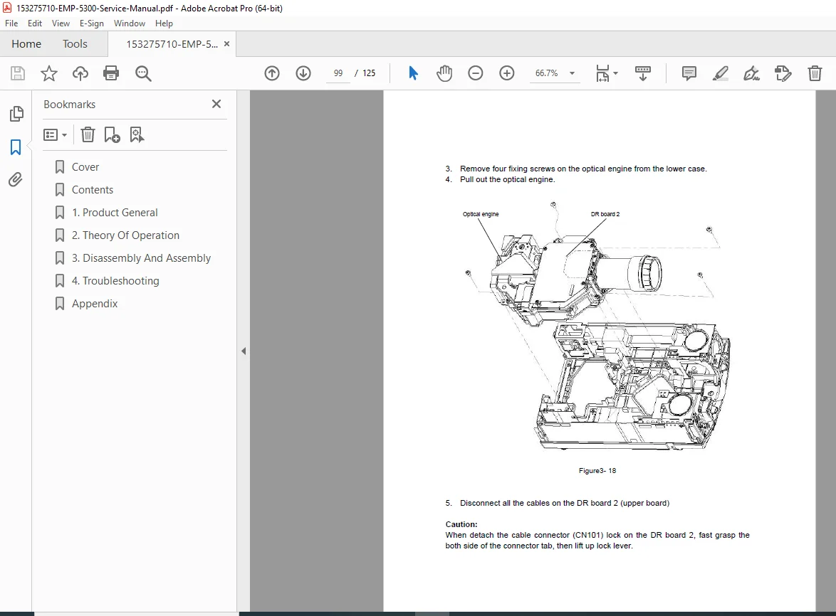
- 3.2.8 Removing the Optical Engine (Page 3-17)
- 3.2.9 Removing the CN Board (Page 3-20)
- 3.2.10 Removing the Power Supply Unit A/B (Page 3-21)
- 3.2.11 Removing the Projection Lens Unit (PLU) (Page 3-27)
- 3.2.12 Removing the Cooling Fan / Optical Head Unit / Light Guide Unit / Exhaust Fan (Page 3-28)
- Chapter 4: Troubleshooting
- 4.1 Before Starting Troubleshooting Procedures (Page 4-1)
- 4.1.1 Tools and Accessories Required for Troubleshooting (Page 4-1)
- 4.1.2 Field Replacement Parts (Page 4-1)
- 4.2 Entry (Page 4-2)
- 4.1 Before Starting Troubleshooting Procedures (Page 4-1)
- Appendix
- Parts List
- Circuit Diagram
- Exploded Diagram
Note: No dedicated index or bookmarks are present in the document, but the detailed table of contents supports quick reference for tasks like Epson projector disassembly procedures, EMP-5500 troubleshooting guide, and Epson EMP-5500 optical engine removal.
This manual is invaluable for legacy Epson SVGA data projector repair and Epson projector power supply unit service, ensuring adherence to manufacturer’s instructions.
File Details
- Manual Name: EPSON EMP-5500 Service Manual
- Models Covered: EMP-5500 (SVGA Data Projector)
- Year: 1998
- Manual PDF Quality: High (clear text, likely scanned from original)
- No of Pages: 125