Epson EMP-TW1000 Projector Service Manual PDF
Original price was: $75.00.$20.95Current price is: $20.95.
Access the comprehensive Epson EMP-TW1000 service manual PDF for in-depth EMP-TW1000 projector troubleshooting guide, Epson home projector repair instructions, EMP-TW1000 disassembly and assembly procedures, Epson projector theory of operation, and EMP-TW1000 safety instructions and specifications. Essential for technicians handling this multimedia home projector model, covering hardware, circuits, and maintenance.
Description
Epson EMP-TW1000 Projector Service Manual – PDF DOWNLOAD
IMAGES:
Description
This Epson EMP-TW1000 service manual PDF is an indispensable resource for service technicians and repair professionals working on the EMP-TW1000 home projector. It delivers detailed Epson home projector repair instructions, including step-by-step EMP-TW1000 disassembly and assembly procedures to safely dismantle and reassemble the unit. The manual features a thorough Epson projector theory of operation, explaining hardware components, internal connections, and functional units like the optical engine, MA board, power supply, and ballast unit.
You’ll find an EMP-TW1000 projector troubleshooting guide with flowcharts for diagnosing issues such as power on/off problems, image display quality, control panel malfunctions, and remote control operations. Additionally, it emphasizes EMP-TW1000 safety instructions and specifications to prevent electric shocks, injuries, and equipment damage, including precautions for static electricity, genuine parts usage, and safety testing like insulation resistance and ground continuity checks.
The document is structured for easy navigation, starting with an introduction on using the manual, precautions (warnings, cautions, reassembly notes, and checkpoints), and a revision history. It then dives into core chapters with diagrams, block diagrams, and pin layouts for practical application.
Table of Contents
- Introduction
- Service Manual description for EMP-TW1000 hardware troubleshooting and field service
- How to use the service manual
- Product lineup notes
- Trademark information
- Precautions
- Definitions for WARNING, CAUTION, REASSEMBLY, and CHECK POINT
- Manual Revision History
- History table (e.g., Rev. A, Date: 2006.11.02, Detail: First Release)
- Service memo section for technical bulletins
- Safety Instructions
- Maintaining Operator Safety (preventing electric shocks, injury, accidents)
- Maintaining the Projector in Good Condition (preventing static damage, use of genuine parts, safety testing)
- Testing procedures (insulation resistance test, ground continuity check, illumination check)
- Other notes (connector handling, cable checks, requirements for service technicians)
- Chapter 1: Product Specifications
- 1.1 Product Features
- 1.1.1 Feature of the projector
- 1.2 Components, Connectors and Switches
- 1.2.1 External Components
- 1.2.2 Internal Components
- 1.2.3 Remote Control
- 1.3 Specifications
- 1.4 Interface Specifications
- 1.4.1 D terminal
- 1.4.2 Component terminal
- 1.4.3 PC
- 1.4.4 HDMI
- 1.4.5 Video (CVBS) Interface
- 1.4.6 S-Video Interface
- 1.4.7 Trigger out
- 1.4.8 RS-232C
- 1.5 External Views
- 1.1 Product Features
- Chapter 2: Theory of Operation
- 2.1 Hardware Overview
- 2.1.1 Circuit Component Connection Diagram
- 2.1.2 Control Circuitry
- 2.2 Optical Engine
- 2.2.1 Lamp Unit
- 2.3 MA Board
- 2.3.1 External View of MA Board
- 2.3.2 Overview of Operation
- 2.4 Interface Connectors
- 2.5 Power Supply Unit
- 2.5.1 Power Supply Circuit Block Diagram
- 2.5.2 Overview of Operation
- 2.5.3 Connector CN4000 Pin Layout
- 2.6 Ballast Unit
- 2.6.1 Power Supply Circuit Block Diagram
- 2.7 RC Receiver Sensor
- 2.8 Temperature Control
- 2.8.1 Sensors and Switches
- 2.8.2 Fan Operation
- 2.9 LED Indicators
- 2.1 Hardware Overview
- Chapter 3: Troubleshooting
- 3.1 Before Carrying Out Troubleshooting
- 3.1.1 Troubleshooting Tools and Equipment
- 3.1.2 Field Replacement Parts
- 3.2 Overview
- 3.2.1 Exterior Check
- 3.2.2 Internal Cable Check
- 3.2.3 Power Supply On/Off
- 3.2.4 Image Display and Quality
- 3.2.5 Control Panel
- 3.2.6 Remote control operation
- 3.2.7 Other
- 3.1 Before Carrying Out Troubleshooting
- Chapter 4: Disassembly/Assembly
- 4.1 Overview
- 4.1.1 Precautions
- 4.1.2 Tools and Equipment
- 4.1.3 Projector-Specific Service Precautions
- 4.2 Projector Disassembly and Assembly
- 4.2.1 Removing the EMP-TW1000 Model Name Plate and EPSON 32H Logo Plate
- 4.2.2 Removing the Air Filter Lid and Air Filter
- 4.2.3 Removing the Lamp Unit Lid and Lamp Unit
- 4.2.4 Removing the Foot; A10, Foot Holder; A, and Foot Rubber
- 4.2.5 Removing the Upper Case; B
- 4.2.6 Removing the SW Board Assy., Cable SW;Au, and SW Button
- 4.2.7 Removing the Focus Ring; B, Zoom Ring; B, Zoom Ring Shade, Zoom Ring Cushion, Front Case Unit; F, RC Board Assy., RCR Cable; FIF, RC Filter, and Exhaust Duct Cushion
- 4.2.8 Removing the MA Ground Plate and MA-IF Board Assy.
- 4.2.9 Removing the IF Case, IF Label; A, IF Shade Sheet, and IF Shade Cushion
- 4.2.10 Removing the IF Panel, RC Board Assy., RCR Cable; FIF, IF Board Assy.
- 4.2.11 Removing the PS Ballast Assy.
- 4.2.12 Removing the Lamp Plate, PS Shade Plate, MA Fasten Plate Left, MA Fasten Plate Right, Shielding Gasket, MA Fasten Support Plate, Lamp Insulation Sheet and Optical Engine
- 4.2.13 Removing the Motor CF Assy., CF SW Assy., Micro SW Assy., Top ML Fasten Spring, Frame CF Assy., and Auto Iris Assy.
- 4.2.14 Removing the Exhaust Fan; B, Exhaust Duct, Inshulock T-18S, TH Board Assy., C Cable; 170, MA Fasten Plate; PS, and Fasten Plate; A
- 4.2.15 Removing the Light Valve Duct, PBS Duct Sheet, Light Valve Intake Duct, Light Valve Sheet, Intake Fan, and Light Valve Cushion
- 4.2.16 Removing the LMP Intake Duct, Lamp Fan, and Lamp Fan Guard
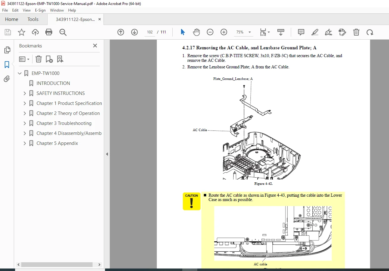
- 4.2.17 Removing the AC Cable, and Lensbase Ground Plate; A
- 4.2.18 Removing the PS Duct, PS Intake Duct, Intake Fan, Intake Fan Frame, Ballast Duct Sheet, PS Duct Sheet, and Light Valve Cushion
- 4.2.19 Removing the Lamp Lid Detection Switch, Lamp Lid Detection Switch Plate, Plate PS Conduction A, Plate PS Conduction B, RC Filter, Heatresistant Sheet; A, Heatresistant Sheet; B, and Lower Case
- 4.1 Overview
- Chapter 5: Appendix
- AS (After Service) menu
No index or bookmarks are explicitly present in the PDF beyond the table of contents. This Epson EMP-TW1000 service manual PDF ensures safe and effective repairs with visual aids like diagrams and photos throughout.
File Details
- Manual Name: Epson EMP-TW1000 Service Manual
- Models Covered: EMP-TW1000
- Year: 2006
- Manual PDF Quality: High-quality scan with clear text, diagrams, and searchable content
- No of Pages: 111