Epson EPL-N1600 Service Manual – PDF DOWNLOAD
$27.95
Epson EPL-N1600 Service Manual – PDF DOWNLOAD
Description
Epson EPL-N1600 Service Manual – PDF DOWNLOAD
FILE DETAILS:
Epson EPL-N1600 Service Manual – PDF DOWNLOAD
Language :English
Pages :210
Downloadable : Yes
File Type : PDF
IMAGES PREVIEW OF THE MANUAL:
DESCRIPTION:
Epson EPL-N1600 Service Manual – PDF DOWNLOAD
About This Manual
This manual describes basic functions, theory of electrical and mechanical operations, maintenance and repair procedures of EPL-N1600. The
instructions and procedures included herein are intended for the experienced repair technicians, and attention should be given to the precautions on the preceding page.
Contents
This manual consists of six chapters and Appendix.
CHAPTER 1. PRODUCT DESCRIPTIONS
Provides a general overview and specifications of the
product.
CHAPTER 2. OPERATING PRINCIPLES
Describes the theory of electrical and mechanical
operations of the product.
CHAPTER 3. TROUBLESHOOTING
Provides the step-by-step procedures for
troubleshooting.
CHAPTER 4. DISASSEMBLY AND ASSEMBLY
Describes the step-by-step procedures for
disassembling and assembling the product.
CHAPTER 5. ADJUSTMENTS
Provides Epson-approved methods for adjustment.
CHAPTER 6. MAINTENANCE
Provides preventive maintenance procedures and the
lists of Epson-approved lubricants and adhesives
required for servicing the product.
APPENDIX Provides the following additional information for
reference:
• Connector pin assignments
• Electric circuit boards components layout
• Exploded diagram
• Electrical circuit boards schematics
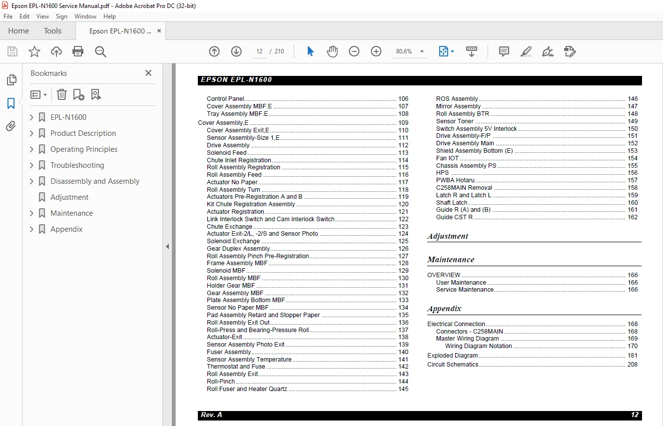
TABLE OF CONTENTS:
Epson EPL-N1600 Service Manual – PDF DOWNLOAD
EPL-N1600 1
PRECAUTIONS 3
About This Manual 4
Safety Information 5
Safety Precautions 5
Power Supply and electrical components 5
Mechanical Components 6
Safety Components 6
Warning/Caution Labels 7
ROS Assy 7
FUSER assy 8
General Cautions 9
Revision Status 10
Table of Contents 11
Product Description 13
11 OVERVIEW 14
111 CONSUMABLES AND OPTIONS 14
12 SPECIFICATIONS 15
121 ENGINE SPECIFICATIONS 15
122 PAPER SPECIFICATIONS 16
123 CONTROLLER SPECIFICATIONS 17
124 ELECTRICAL SPECIFICATIONS 18
125 CONSUMABLES 18
126 OTHER SPECIFICATIONS 18
127 ENVIRONMENTAL SPECIFICATIONS 19
Main unit and consumables 19
CONSUMABLES 19
128 OPERATING CONDITIONS 20
129 SAFETY APPROVAL 21
1210 RELIABILITY, DURABILITY AND MAINTENABILITY 22
1211 EXTERNAL DIMENSIONS AND WEIGHT 23
13 INTERFACE SPECIFICATIONS 24
131 Bidirectional Parallel Interface 24
132 Serial Interface 25
14 OPERATING SPECIFICATIONS 26
LCD panel 26
LED Lamps 26
BUTTONS 27
141 Panel Settings 28
1411 OneTouch Mode 28
1412 SelecType Mode 28
142 Printer Status Messages 31
143 Initialization Process 32
144 Special Functions 33
145 OTHER SPECIFICATIONS 34
1451 Jumper Settings 34
1452 Program-ROM Specifications 34
1453 RAM Capacity 35
1454 Operating Precaution 35
Operating Principles 36
21 OVERVIEW 37
211 Electrophotographic Printing 37
212 Paper Transportation 39
213 Main Engine Components Function 40
Paper cassette (standard) 40
Paper Transportation I 41
Paper Transportation I Rear 42
Paper Transportation II (1) 43
paper transportation II (2) 44
Fusing and Paper Exit 45
Xerographic Modules 47
Drive Modules 51
Electrical Modules 52
Frame 53
214 Main Control Circuit 54
Troubleshooting 55
31 OVERVIEW 56
311 Service-Call Errors 56
312 Printer Messages 58
3121 Status Messages 59
3122 Error Messages 60
3123 Warning Messages 64
32 Troubleshooting 65
321 Troubleshooting with Error Messages 65
11 Service req E0008 65
12 service req E0004 66
13 service req E0003 67
14 service req E0005 68
15 error message “Printer open” 69
16 Error message “exiting paper jam” 70
17 Error message “PAper jam” 70
18 ERROR MESSAGE “INSERT IMAGING CRTG” 72
19 ERROR MESSAGE “INSERT LC1” 73
322 Troubleshooting with Printer Operation 74
21 Printer does not operate properly 74
22 Abnormal Print Operaiton 78
23 Electrical Noise 79
323 Troubleshooting with Print Image Quality 80
31 Light (Undertone) Print 80
32 BLANK Print (No image) 82
33 BLAcK Print 84
34 vertical white banding 85
35 HORIZONTAL white banding 86
36 vertical Black STreaks 87
37 HORIZOnTAL black STREAKS 88
38 white Spot 89
39 BLACK Spot 90
310 GHOST PRINT 91
311 DIRTY BACKBROUND 92
312 Skewed printing 93
313 DAMAGED printing 94
314 UNFUSED IMAGE 95
315 MISREGISTRATION 96
Disassembly and Assembly 97
41 OVERVIEW 98
411 Precautions 98
412 Tools 99
413 Pre-Shipment Check 99
414 Special Operaiton for Service 99
42 DISASSEMBLY AND ASSEMBLY101
421 Cover Side,E102
422 Shield Assembly TopST103
423 Control Panel104
424 Cover Assembly MBFE105
425 Tray Assembly MBFE106
43 Cover Assembly,E107
431 Cover Assembly Exit,E108
432 Sensor Assembly-Size 1,E109
433 Drive Assembly110
434 Solenoid Feed111
435 Chute Inlet Registration112
436 Roll Assembly Registration113
437 Roll Assembly Feed114
438 Actuator No Paper115
439 Roll Assembly Turn116
4310 Actuators Pre-Registration A and B117
4311 Kit Chute Registration Assembly118
4312 Actuator Registration119
4313 Link Interlock Switch and Cam Interlock Switch120
4314 Chute Exchange121
4315 Actuator Exit-2/L, -2/S and Sensor Photo122
4316 Solenoid Exchange123
4317 Gear Duplex Assembly124
4318 Roll Assembly Pinch Pre-Registration125
4319 Frame Assembly MBF126
4320 Solenoid MBF127
4321 Roll Assembly MBF128
4322 Holder Gear MBF129
4323 Gear Assembly MBF130
4324 Plate Assembly Bottom MBF131
4325 Sensor No Paper MBF132
4326 Pad Assembly Retard and Stopper Paper133
4327 Roll Assembly Exit Out134
4328 Roll-Press and Bearing-Pressure Roll135
4329 Actuator-Exit136
4330 Sensor Assembly Photo Exit137
4331 Fuser Assembly138
4332 Sensor Assembly Temperature139
4333 Thermostat and Fuse140
4334 Roll Assembly Exit141
4335 Roll-Pinch142
4336 Roll Fuser and Heater Quartz143
4337 ROS Assembly144
4338 Mirror Assembly145
4339 Roll Assembly BTR146
4340 Sensor Toner147
4341 Switch Assembly 5V Interlock148
4342 Drive Assembly-F/P149
4343 Drive Assembly Main150
4344 Shield Assembly Bottom (E)151
4345 Fan IOT152
4346 Chassis Assembly PS153
4347 HPS154
4348 PWBA Hotaru155
4349 C258MAIN Removal156
4350 Latch R and Latch L157
4351 Shaft Latch158
4352 Guide R (A) and (B)159
4353 Guide CST R160
Adjustment161
Maintenance163
61 OVERVIEW164
611 User Maintenance164
612 Service Maintenance164
Appendix165
71 Electrical Connection166
711 Connectors – C258MAIN166
712 Master Wiring Diagram167
7121 Wiring Diagram Notation168
HPS – Controller169
HPS – Imaging Cartridge / Toner Sensor171
Controller – ROS Assy, SOS Sensor, and Switch Assy 5V Interlock172
Controller – Motor Assy Main, and Solenoid Exchange174
Controller – Sensor Exit, Sensor Photo, and Thermistor175
Controller – PWB Assembly-Size 1176
72 Exploded Diagram179
Covers179
Paper Casette181
Paper Transportation (I)183
Paper Transportation (I) Rear185
Paper Transportation (II)187
MBF189
Fusing & Paper Exit191
Fuser Unit193
Xerographic Module195
Drive Module197
Electrical Module199
MCU201
Controller203
Frame205
73 Circuit Schematics207
S.M 28/2/2025