EPSON EPL-N4000EPL-N4000+ Service Manual – PDF DOWNLOAD
$26.95
EPSON EPL-N4000EPL-N4000+ Service Manual – PDF DOWNLOAD
Description
EPSON EPL-N4000EPL-N4000+ Service Manual – PDF DOWNLOAD
FILE DETAILS:
EPSON EPL-N4000EPL-N4000+ Service Manual – PDF DOWNLOAD
Language :English
Pages :195
Downloadable : Yes
File Type : PDF
IMAGES PREVIEW OF THE MANUAL:
DESCRIPTION:
EPSON EPL-N4000EPL-N4000+ Service Manual – PDF DOWNLOAD
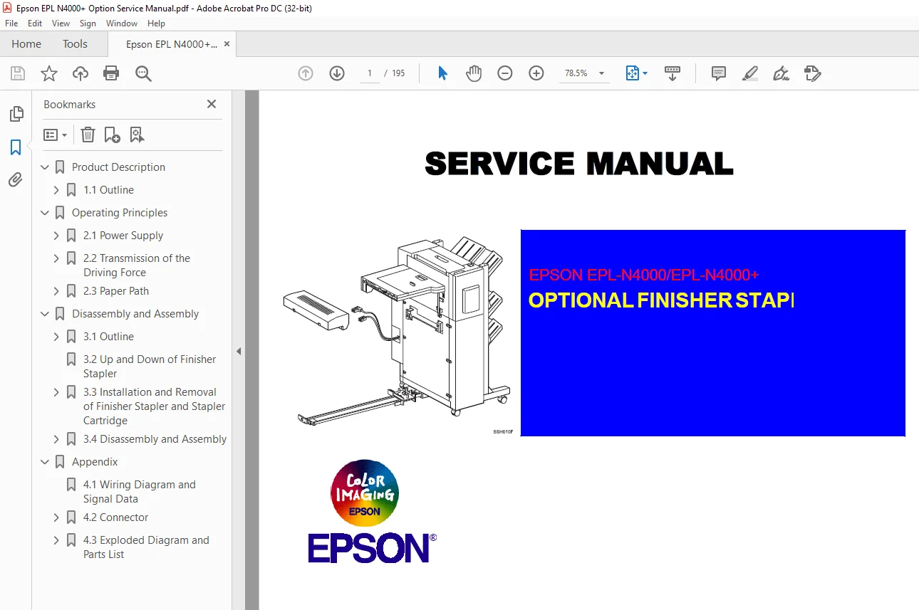
About This Manual
This manual describes basic functions, theory of electrical and mechanical operations, and repair procedures of EPL-N4000/N-400+ Optional Finisher Stapler. The instructions and procedures included herein are intended for the experienced repair technicians, and attention should be given to the precautions on the preceding page
Contents
This manual consists of three chapters and Appendix.
CHAPTER 1. PRODUCT DESCRIPTIONS
Provides a general overview and specifications of the
product.
CHAPTER 2. OPERATING PRINCIPLES
Describes the theory of electrical and mechanical
operations of the product.
CHAPTER 3. DISASSEMBLY AND ASSEMBLY
Describes the step-by-step procedures for
disassembling and assembling the product.
APPENDIX Provides the following additional information for
reference:
• Connector pin assignments
• Electric circuit boards components layout
• Exploded diagram
TABLE OF CONTENTS:
EPSON EPL-N4000EPL-N4000+ Service Manual – PDF DOWNLOAD
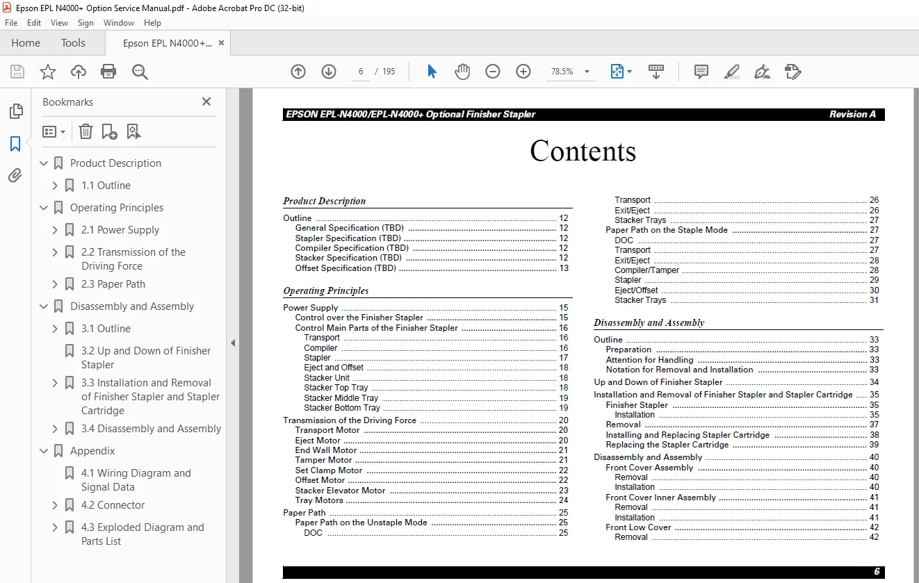
Product Description
Outline 12
General Specification (TBD) 12
Stapler Specification (TBD) 12
Compiler Specification (TBD) 12
Stacker Specification (TBD) 12
Offset Specification (TBD) 13
Operating Principles
Power Supply 15
Control over the Finisher Stapler 15
Control Main Parts of the Finisher Stapler 16
Transport 16
Compiler 16
Stapler 17
Eject and Offset 18
Stacker Unit 18
Stacker Top Tray 18
Stacker Middle Tray 19
Stacker Bottom Tray 19
Transmission of the Driving Force 20
Transport Motor 20
Eject Motor 20
End Wall Motor 21
Tamper Motor 21
Set Clamp Motor 22
Offset Motor 22
Stacker Elevator Motor 23
Tray Motors 24
Paper Path 25
Paper Path on the Unstaple Mode 25
DOC 25
Transport 26
Exit/Eject 26
Stacker Trays 27
Paper Path on the Staple Mode 27
DOC 27
Transport 27
Exit/Eject 28
Compiler/Tamper 28
Stapler 29
Eject/Offset 30
Stacker Trays 31
Disassembly and Assembly
Outline 33
Preparation 33
Attention for Handling 33
Notation for Removal and Installation 33
Up and Down of Finisher Stapler 34
Installation and Removal of Finisher Stapler and Stapler Cartridge 35
Finisher Stapler 35
Installation 35
Removal 37
Installing and Replacing Stapler Cartridge 38
Replacing the Stapler Cartridge 39
Disassembly and Assembly 40
Front Cover Assembly 40
Removal 40
Installation 40
Front Cover Inner Assembly 41
Removal 41
Installation 41
Front Low Cover 42
RemoInstallation 42
L/H Cover 43
Removal 43
Installation 43
L/H Cover Low 44
Removal 44
Installation 44
Eject Cover 45
Removal 45
Installation 45
Rear Cover 46
Removal 46
Installation 46
Harness Cover 46
Removal 46
Installation 46
Add Cover 47
Removal 47
Installation 47
Finisher Stapler PWB Cover and Connector Cover 48
Removal 48
Installation 48
Stacker Upper Limit Switch 50
Removal 50
Installation 50
Stacker Lower Limit Switch 51
Removal 51
Installation 51
Finisher Stapler Interlock Sensor and Actuator 52
Removal 52
Installation 52
Stacker Tray ID Sensor 53
Removal 53
Installation 53
R/H Rack Cover Assembly 54
Removal 54
Installation 55
Stacker Elevator Motor 56
Removal 56
Installation 56
Bottom (Lower) Tray Assembly 57
Removal 57
Installation 57
Bottom Tray Front Cover 58
Removal 58
Installation 58
Bottom Tray Half and Full Sensors 59
Removal 59
Installation 59
Bottom Tray Lower and Upper Limit Sensor 60
Removal 60
Installation 60
Bottom Tray 61
Removal 61
Installation 61
Bottom Tray Paper Sensor 62
Removal 62
Installation 62
Bottom Tray Safety Sensor 63
Removal 63
Installation 63
Bottom Tray Motor 64
Removal 64
Installation 64
Bottom Tray Drive Belts 65
Removal 65
Installation 66
Middle Tray Assembly 67
Removal 67
Installation 67
Middle Tray Front Cover 68
Removal 68
Installation 68
Middle Tray Half and Full Sensors 69
Removal 69
Installation 69
Middle Tray Lower and Upper Limit Sensor 70
Removal 70
Installation 70
Middle Tray 71
val 42
Removal 71
Installation 71
Middle Tray Paper Sensor 72
Removal 72
Installation 72
Middle Tray Motor 73
Removal 73
Installation 73
Middle Tray Drive Belts 74
Removal 74
Installation 75
Middle Tray Safety Switch 76
Removal 76
Installation 76
Top Tray Assembly 77
Removal 77
Installation 77
Top Tray Front Cover 78
Removal 78
Installation 78
Top Tray Half and Full Sensors 79
Removal 79
Installation 79
Top Tray Lower and Upper Limit Sensor 80
Removal 80
Installation 80
Top Tray 81
Removal 81
Installation 81
Top Tray Paper Sensor 82
Removal 82
Installation 82
Top Tray Motor 83
Removal 83
Installation 83
Top Tray Drive Belts 84
Removal 84
Installation 85
Top Tray Safety Switch 86
Removal 86
Installation 86
Tamper Motor 87
Removal 87
Installation 87
Tamper Home Sensor 88
Removal 88
Installation 88
Compiler Paper Sensor 89
Removal 89
Installation 89
End Wall Open Sensor 90
Removal 90
Installation 90
Tamper Motor Drive Belt 91
Removal 91
Installation 91
Compiler Tray Solenoid Assembly 92
Removal 92
Installation 92
Eject Shaft Assemblies 93
Removal 93
Installation 93
Upper Exit Chute Assembly 95
Removal 95
Installation 95
Exit Shaft Assembly 96
Removal 96
Installation 96
Paddle Shaft Assembly 97
Removal 97
Installation 98
Eject Chute Assembly 99
Removal 99
Installation 99
Eject Pinch Roll Shaft Assembly 100
Removal 100
Installation 100
Stack Height Sensor 101
Removal 101
Installation 101
Paddle Drive Belt 102
Removal 102
Installation 102
Stapler Assembly 103
Removal 103
Installation 103
Stapler Position Sensors 104
Removal 104
Installation 104
Top Cover Assembly 105
Removal 105
Installation 105
Compiler Tray Exit Sensor 106
Removal 106
Installation 106
Upper Transport Chute Assembly 107
Removal 107
Installation 107
Top and Front Cover Interlock Switches 108
Removal 108
Installation 108
Compiler Cover and Safety Interlock Switches 109
Removal 109
Installation 110
Unload While Run Switch 111
Removal 111
Installation 111
End Wall Motor 112
Removal 112
Installation 113
Transport Motor 114
Removal 114
Installation 114
Set Clamp Motor 115
Removal 115
Installation 115
Set Clamp Motor Drive Belt 116
Removal 116
Installation 116
Set Clamp Home Sensor 116
Removal 116
Installation 116
Eject Motor 117
Removal 117
Installation 117
Stapler Transport Motor 118
Removal 118
Installation 118
Stapler Transport Motor Drive Belt 119
Removal 119
Installation 119
Transport Motor Drive Belt 120
Removal 120
Installation 120
Eject Bracket Assembly 121
Removal 121
Installation 121
Eject Clamp Offset Motor 122
Removal 122
Installation 122
Eject Clamp Sensor 123
Removal 123
Installation 123
Offset Home Sensor 124
Removal 124
Installation 124
Finisher Stapler PWB Assembly 125
Removal 125
Installation 125
LVPS (OP11/OPR4H) 126
Removal 126
Installation 126
DOC Cover Assembly 127
Removal 127
Installation 127
IN Gate Support Assembly 128
Removal 128
Installation 128
IN Gate Support Actuator 129
Removal 129
Installation 129
Transport Assembly 130
Removal 130
Installation 130
Transport Assembly Drive Belt 131
Removal 131
Installation 132
IN Gate Interlock Switch 133
Removal 133
Installation 133
IN Gate Solenoid Assembly 134
Removal 134
Installation 134
Roller Unit 135
Removal 135
Installation 135
Transport Cover Assembly 136
Removal 136
Installation 136
Transport Interlock Sensor 137
Removal 137
Installation 137
Transport Roll 138
Removal 138
Installation 138
Transport Entrance Sensor 140
Removal 140
Installation 140
IOT Paper Full Sensor 141
Removal 141
Installation 141
Transport Exit Sensor 142
Removal 142
Installation 142
Appendix
Wiring Diagram and Signal Data 144
Connector 154
P/J Connector Table and Location Map 154
Exploded Diagram and Parts List 165
HCS Transport 165
HCS Covers Front 166
HCS Covers Rear 167
Rack 168
Rails and Trays 169
Lower Tray 171
Lower Tray Frame 173
Middle Tray 174
Middle Tray Frame 176
Top Tray 178
Top Tray Frame 180
Tray Eject 181
Exit 183
Offset and Eject 184
Stapler 185
Transport 186
Front Frame 187
Rear Frame 1 188
Rear Frame 2 189
Rear Frame 3 190
Electrical Module 191
Harness 192
HCS DOC 193
Frame Transport, Rear 194
Frame Transport, Open 195
S.M 26/2/2025