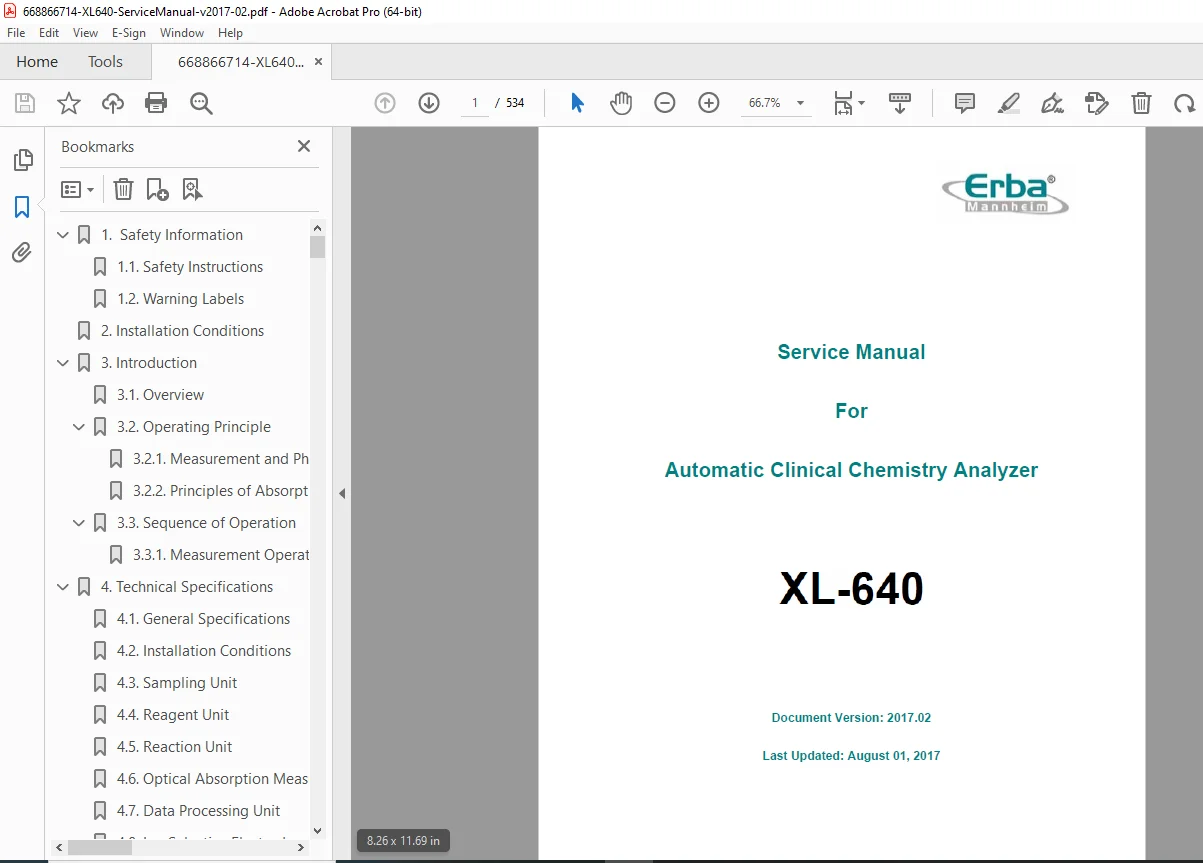
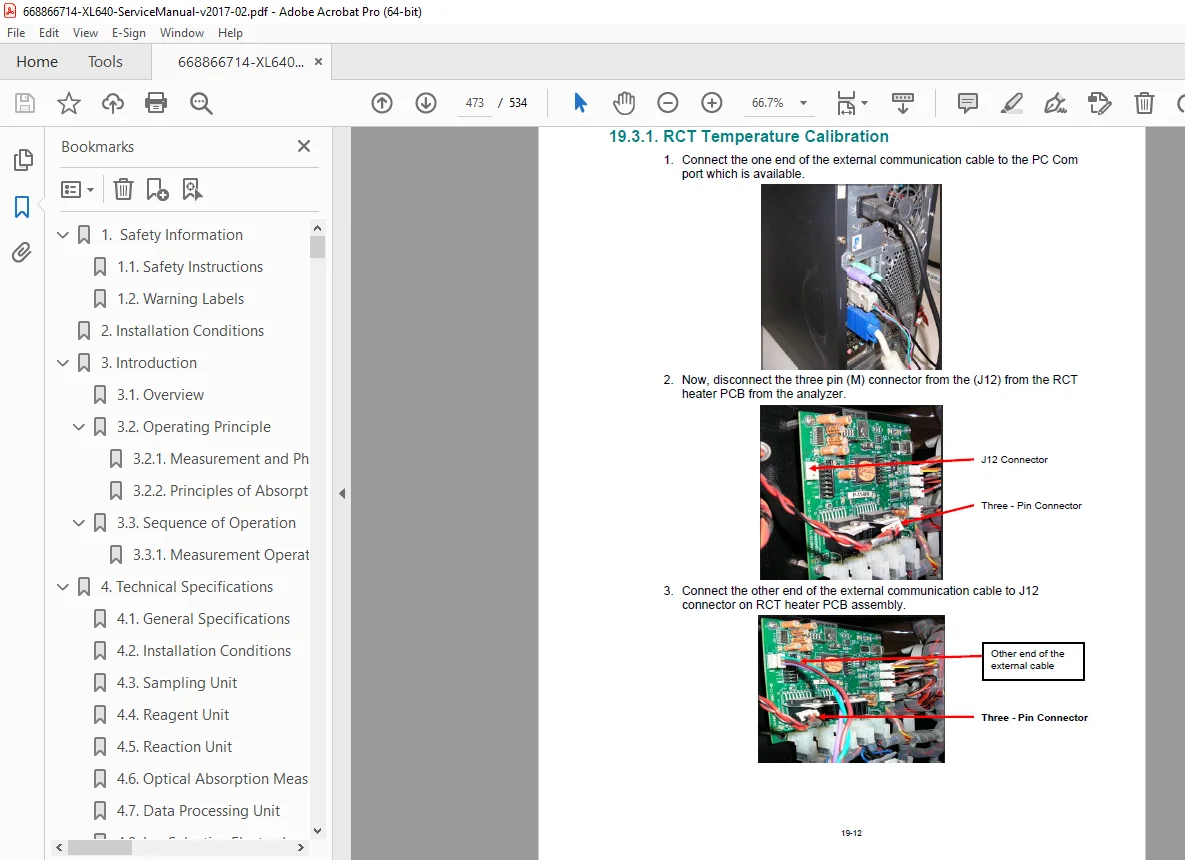
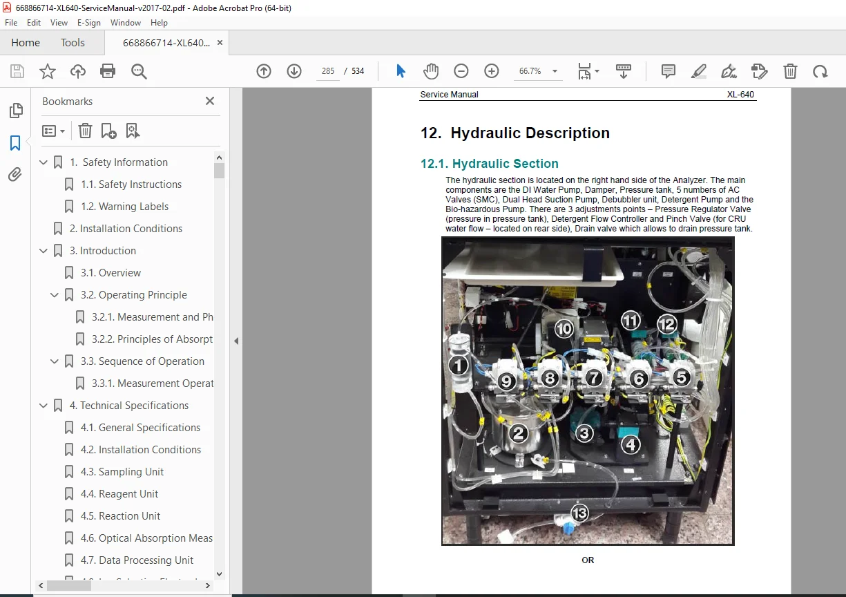
Erba XL-640 Service Manual PDF Clinical Chemistry Analyzer Repair Maintenance PDF
Original price was: $85.00.$20.95Current price is: $20.95.
Official Erba Diagnostics XL-640 service manual for automatic clinical chemistry analyzers. This comprehensive 534-page technical manual (Version 2017.02, August 2017) covers installation procedures, functional descriptions, electronic circuit diagrams, PCB assemblies, wiring diagrams, troubleshooting procedures, ISE electrode maintenance, photometer calibration, preventive maintenance schedules, component replacement, and complete service information for qualified biomedical technicians servicing XL-640 chemistry analyzers in clinical laboratories.
Description
Erba XL-640 Service Manual PDF Clinical Chemistry Analyzer Repair Maintenance – PDF DOWNLOAD
LONG DESCRIPTION
This is the official Erba Diagnostics XL-640 Service Manual (Document Version 2017.02, Last Updated August 01, 2017) for the XL-640 Automatic Clinical Chemistry Analyzer. This comprehensive 534-page technical manual provides complete service, maintenance, and repair information for qualified biomedical equipment technicians and service engineers to install, calibrate, troubleshoot, and maintain these advanced automated clinical chemistry systems used in hospital laboratories, reference labs, and clinical diagnostic facilities worldwide.
Product Overview
Erba XL-640 Clinical Chemistry Analyzer:
The XL-640 represents an advanced automatic clinical chemistry analyzer designed for high-throughput biochemical testing in clinical laboratories. This sophisticated system combines automated sample handling, reagent management, precise photometric measurement, ion-selective electrode (ISE) technology, and integrated data processing to deliver accurate and reliable clinical chemistry results for comprehensive metabolic panels, liver function tests, kidney function tests, lipid profiles, and electrolyte analysis.
Key Applications:
- Hospital clinical laboratories
- Reference laboratories
- Diagnostic centers
- Research laboratories
- Blood banks
- Medical clinics
- University teaching hospitals
- Public health laboratories
- Veterinary diagnostic labs
- Pharmaceutical QC laboratories
System Capabilities
Test Menu:
- Comprehensive metabolic panel
- Liver function tests (LFT)
- Kidney function tests (RFT/KFT)
- Lipid profile
- Cardiac markers
- Electrolytes (Na+, K+, Cl-, CO2)
- Special chemistry tests
- Enzymes
- Substrates
- Proteins
- Immunoturbidimetric assays
Automated Features:
- Continuous loading capability
- STAT priority testing
- Automatic sample identification (barcode)
- Automatic reagent identification (barcode)
- Onboard reagent refrigeration
- Automated sample pipetting
- Automated reagent pipetting
- Automatic cuvette washing
- Collision detection
- Clot detection
- Liquid level sensing
Technical System Components
Sampling Unit:
- Automated sample pipette
- Sample barcode reader
- Sample tray (capacity specified)
- Collision detection
- Liquid level sensing
- Clot detection
- Pediatric sample capability
Reagent Unit:
- Refrigerated reagent compartment
- Reagent barcode reader
- R1 and R2 pipette systems
- Reagent tray with cooling
- Multiple reagent position capacity
- Temperature monitoring
Reaction Unit:
- Reaction tray (cuvette rotor)
- Temperature-controlled reaction disk
- Magnetic stirrers
- Cuvette rinsing unit (CRU)
- Washing station
Optical System:
- Photometer unit
- Multiple wavelength capability
- Halogen lamp light source
- Interference filters
- Photodiode detection
- Absorbance measurement
- Kinetic and endpoint methods
ISE Unit:
- Ion-Selective Electrode module
- Na+, K+, Cl- measurement
- Reference electrode
- ISE calibration system
- Buffer solutions
- Automatic calibration
Data Processing:
- Integrated computer system
- MultiXL software
- Windows-based interface
- Database management
- Quality control
- Result reporting
- LIS/HIS connectivity
Comprehensive Manual Contents
DOCUMENT INFORMATION:
- Title: Service Manual for XL-640
- Document Version: 2017.02
- Last Updated: August 01, 2017
- Author: Prasad Patil
- Creator: Acrobat PDFMaker 10.0 for Word
- Pages: 534 pages
- Manufacturer: Erba Diagnostics Mannheim GmbH, Germany
- Address: Mallaustrasse 69-73, 68219 Mannheim, Germany
FOREWORD AND LEGAL INFORMATION
Manual Purpose:
- Instructional aide for servicing and maintenance
- Reference for easy troubleshooting
- Detailed feature descriptions
- Complete specifications
- PCB assembly information
- Wiring diagrams
- Replacement procedures
Service Engineer Requirements:
- Read and understand this manual
- Be trained by authorized person
- Be familiar with analyzer operation
Legal Information:
- All rights reserved by manufacturer
- Copyright protected document
- Confidential and proprietary information
- No modification or reproduction without permission
- Subject to change without notice
- For authorized recipients only
COMPLETE TABLE OF CONTENTS
CHAPTER 1: SAFETY INFORMATION (Pages 1-1 to 1-2)
1.1 Safety Instructions:
- General safety precautions
- Electrical safety
- Biological hazard warnings
- Chemical hazard warnings
- Mechanical hazard warnings
- Service personnel safety
- Patient safety considerations
- Environmental safety
1.2 Warning Labels:
- Label locations on analyzer
- Label meanings and symbols
- Biohazard warnings
- Electrical warnings
- High voltage warnings
- Moving parts warnings
- Hot surface warnings
CHAPTER 2: INSTALLATION CONDITIONS (Page 2-1)
- Site requirements overview
- Environmental specifications
- Space requirements
- Power requirements
- Connectivity requirements
CHAPTER 3: INTRODUCTION (Pages 3-1 to 3-4)
3.1 Overview:
- System description
- Clinical chemistry analyzer functionality
- Automation capabilities
3.2 Operating Principle:
3.2.1 Measurement and Photometry:
- Photometric analysis principles
- Light absorption measurement
- Wavelength selection
- Optical path description
3.2.2 Principles of Absorption Photometry:
- Beer-Lambert Law
- Absorbance calculation
- Concentration determination
- Measurement accuracy
3.3 Sequence of Operation:
- Sample processing workflow
- Reagent dispensing sequence
- Reaction monitoring
- Measurement timing
- Result calculation
3.3.1 Measurement Operation Table:
- Step-by-step operation sequence
- Timing diagrams
- Process flow
CHAPTER 4: TECHNICAL SPECIFICATIONS (Pages 4-1 to 4-12)
4.1 General Specifications:
- System dimensions
- Weight specifications
- Power requirements
- Throughput specifications
- Precision specifications
- Linearity specifications
4.2 Installation Conditions:
- Environmental requirements
- Temperature range
- Humidity specifications
- Altitude specifications
4.3 Sampling Unit:
- Sample volume range
- Sample types accepted
- Sample tray capacity
- Pipetting accuracy
- Pipetting precision
4.4 Reagent Unit:
- Reagent positions
- Reagent volume range
- Refrigeration temperature
- Temperature stability
- Reagent pipetting specifications
4.5 Reaction Unit:
- Number of cuvettes
- Cuvette path length
- Reaction temperature
- Temperature stability
- Incubation time range
4.6 Optical Absorption Measurement Unit:
- Wavelength range
- Available wavelengths
- Filter specifications
- Light source specifications
- Detector specifications
- Absorbance range
- Photometric accuracy
- Photometric linearity
4.7 Data Processing Unit:
- Computer specifications
- Operating system
- RAM and storage
- Display specifications
- Printer compatibility
- Network connectivity
4.8 Ion Selective Electrodes:
- ISE parameters (Na+, K+, Cl-)
- Measurement range
- Accuracy specifications
- Precision specifications
- Response time
- Calibration frequency
4.9 Computer Specifications:
- CPU requirements
- Memory requirements
- Hard drive capacity
- Display resolution
- Operating system compatibility
4.10 Technical Features:
4.10.1 Salient Technical Features:
- Key system capabilities
- Automation features
- Quality control features
- User interface features
4.10.2 Other Features:
- Additional functionality
- Optional features
- Expandability options
4.11 Equipment Overview:
4.11.1 Front View:
- Front panel layout
- Component identification
- Control locations
4.11.2 Left Side View:
- Left side components
- Access panels
- Connection points
4.11.3 Right Side View:
- Right side components
- Service access
- Auxiliary connections
CHAPTER 5: PRE-INSTALLATION (Pages 5-1 to 5-3)
5.1 Floor Requirements:
- Load-bearing capacity
- Level surface requirements
- Vibration isolation
- Anti-static flooring
5.2 Electrical Requirements:
- Voltage specifications
- Current requirements
- Grounding requirements
- Circuit protection
- UPS recommendations
5.3 Site Requirements:
5.3.1 Environmental Requirements:
- Temperature range
- Humidity range
- Air quality requirements
- Ventilation needs
5.3.2 External Interferences:
- Electromagnetic interference
- Vibration sources
- Chemical fumes
- Dust control
5.3.3 Proper Room Lighting:
- Illumination requirements
- Light source specifications
- Glare prevention
CHAPTER 6: INSTALLATION (Pages 6-1 to 6-68)
6.1 Basic Operational Information:
6.1.1 Procedure to Install XL-640 Analyzer:
- Installation checklist
- Pre-installation verification
- Installation sequence
6.2 Unpacking the Analyzer:
- Shipping container handling
- Unpacking sequence
- Component identification
- Damage inspection
6.3 Inspections and Accessories Checklist:
- Standard accessories list
- Optional accessories
- Consumables list
- Documentation checklist
- Tools and spare parts
6.4 Installing Components:
6.4.1 Installing Sample Tray and Reagent Tray:
- Tray installation procedures
- Positioning and alignment
- Securing mechanisms
6.4.2 Installing DI Water, Cleaning, Bio-hazardous and Waste Cans:
- Can placement
- Tubing connections
- Float sensor installation
- Capacity specifications
6.4.3 USB Communication (New):
- USB cable connection
- Driver installation
- Communication verification
- Troubleshooting USB connection
6.4.4 Serial Communication (Old):
- RS-232 cable connection
- COM port configuration
- Communication settings
- Testing serial connection
6.4.5 Printer Installation:
- DeskJet printer setup
- Laser printer setup
- Driver installation
- Print test
6.4.6 Power On:
- Initial power-up sequence
- System initialization
- Self-test verification
- Error checking
6.5 Software Installation:
6.5.1 Overview:
- Software package description
- Installation requirements
- Installation overview
6.5.2 Pre-requisite:
- Operating system requirements
- .NET Framework installation
- SQL Server installation
- Other dependencies
6.5.3 Installing MultiXL Software:
- Step-by-step installation
- Database setup
- User creation
- License activation
- Configuration settings
6.5.4 Upgrading MultiXL Software:
- Backup procedures
- Upgrade process
- Database migration
- Verification testing
6.5.5 Database Utility Options:
- Database backup
- Database restore
- Database maintenance
- Data export/import
6.5.6 Accessing MultiXL Software:
- Login procedures
- User authentication
- Password management
- User levels and permissions
6.5.7 Password Recovery Procedure:
- Administrator password reset
- User password recovery
- Security considerations
6.5.8 Main Menu Software Layout:
- User interface overview
- Menu navigation
- Function buttons
- Screen layout
6.6 Display Language Settings:
- Language selection
- Regional settings
- Date/time format
6.7 Installing Touch Screen Monitor:
- Touchscreen connection
- Driver installation
- Calibration procedures
- Testing touch functionality
CHAPTER 7: RELOCATION (Pages 7-1 to 7-7)
7.1 Tools and Materials for Packing:
- Packing materials list
- Tools required
- Protective materials
- Original packaging (if available)
7.2 Uninstalling and Decontaminating:
- Shutdown procedures
- Fluid drainage
- Decontamination procedures
- Chemical neutralization
- Biological hazard management
- Component disconnection
7.3 Packing the Analyzer:
- Disassembly sequence
- Component protection
- Secure packing methods
- Labeling for transport
- Shipping preparation
7.4 Decontamination Certificate:
- Certificate template
- Required information
- Signatures and dates
- Regulatory compliance
CHAPTER 8: FUNCTIONAL DESCRIPTION (Pages 8-1 to 8-14)
8.1 Identification of Main Components:
- Component locations
- Component naming
- Assembly identification
8.2 Functionality:
8.2.1 Auto Sampler Unit:
- Sample tray mechanism
- X-Y-Z axis movement
- Positioning accuracy
- Sample tube detection
8.2.2 Sample Barcode Reader:
- Barcode scanner type
- Supported barcode formats
- Reading accuracy
- Troubleshooting
8.2.3 Sample Pipette Unit:
- Pipette mechanism
- Volume accuracy
- Liquid level sensing
- Clot detection
- Collision detection
- Washing procedures
8.2.4 Reagent 1 and 2 Pipette Units (R1PT and R2PT):
- R1/R2 pipette systems
- Independent operation
- Volume specifications
- Accuracy and precision
- Maintenance procedures
8.2.5 Reaction Tray (RCT):
- Cuvette rotor design
- Number of positions
- Temperature control
- Rotation mechanism
- Position sensing
8.2.6 Reagent Tray (RGT):
- Reagent positions
- Position numbering
- Temperature zones
- Cooling system
8.2.7 Reagent Barcode Reader:
- Reader location
- Automatic identification
- Supported formats
- Calibration
8.2.8 RGT Cooling Unit:
- Cooling system design
- Temperature control
- Temperature monitoring
- Maintenance
8.2.9 Photometer Unit:
- Optical system layout
- Light path
- Filter wheel
- Detector array
- Signal processing
8.2.10 Stirrer Unit:
- Magnetic stirrer design
- Stirring mechanism
- Speed control
- Positioning
8.2.11 Cuvette Rinsing Unit (CRU):
- Washing station design
- Washing cycle
- Detergent system
- DI water system
- Drying system
- Waste removal
8.2.12 Pipetting Pump Assembly:
- SPP (Sample Pipette Pump)
- R1PP (Reagent 1 Pipette Pump)
- R2PP (Reagent 2 Pipette Pump)
- Syringe specifications
- Valve operation
- Pressure monitoring
8.2.13 Ion Selective Electrode Unit (ISE):
- ISE module design
- Electrode types
- Reference electrode
- Calibration solutions
- Sample/calibrator flow
- Measurement cycle
- Maintenance procedures
- Electrode conditioning
- Electrode replacement
8.2.14 Liquid Level Sensing:
- Float sensors operation
- DI water level
- Waste level
- Cleaning solution level
- Bio-hazardous waste level
- Alarm conditions
CHAPTER 9: ELECTRONICS CIRCUIT DESCRIPTION (Pages 9-1 onwards)
9.1 Electronic Description:
9.1.1 Electronic Functional Block Diagram:
- System architecture
- Major subsystems
- Signal flow
- Power distribution
- Communication buses
9.1.2 Regulator PCB: ELS22032R1:
- Power regulation circuits
- Voltage outputs
- Circuit schematic
- Component locations
- Troubleshooting
9.1.3 Isolation Board ELS22030R2:
- Signal isolation
- Optical isolation
- Circuit protection
- Schematic diagram
- Testing procedures
9.1.4 Opto PCB POS1 ELS22006R3:
- Position sensing circuits
- Optical sensors
- Signal conditioning
- Circuit diagram
9.1.5 Photometer XL V2 R1 ELS52013R2:
- Photometer electronics
- Photodiode amplifiers
- A/D conversion
- Signal processing
- Calibration procedures
9.1.6 LSH PCB and LLS PCB (OLD):
- Liquid level sensing (old version)
- Circuit description
- Sensor interface
9.1.7 New LLS PCB ASSY: ELS22036R2.1:
- Updated liquid level sensing
- Sample, R1, R2 arm assembly
- Circuit improvements
- Installation procedures
9.1.8 New LLS PCB ASSY: ELS52023R0:
- Alternative LLS design
- Specifications
- Configuration
9.1.9 Backplane 1 ELS52005R2:
- Backplane architecture
- Board interconnections
- Power distribution
- Signal routing
- Connector pinouts
9.1.10 Backplane 2 ELS32010R1:
- Secondary backplane
- Expansion capabilities
- Circuit description
9.1.11 Interface PCB ELS52016R1:
- Computer interface
- Communication protocols
- I/O control
- Circuit schematic
Additional PCB Assemblies: (Continued detailed descriptions of all electronic boards)
REMAINING CHAPTERS (Based on typical clinical chemistry analyzer service manual structure)
CHAPTER 10: WIRING DIAGRAMS
- Power wiring diagrams
- Signal wiring diagrams
- Motor connections
- Sensor connections
- Solenoid valve wiring
- Pump wiring
- ISE module wiring
- Complete system wiring
CHAPTER 11: PREVENTIVE MAINTENANCE
- Daily maintenance tasks
- Weekly maintenance tasks
- Monthly maintenance tasks
- Quarterly maintenance tasks
- Annual maintenance tasks
- Maintenance log sheets
- Consumables replacement
- Cleaning procedures
CHAPTER 12: TROUBLESHOOTING
- Systematic troubleshooting approach
- Error messages and codes
- Symptom-based diagnosis
- Component testing procedures
- Calibration verification
- Performance testing
- Corrective actions
CHAPTER 13: CALIBRATION AND ADJUSTMENT
- Photometer calibration
- ISE calibration
- Pipette calibration
- Temperature calibration
- Position calibration
- Software calibration procedures
CHAPTER 14: COMPONENT REPLACEMENT
- Sample pipette replacement
- Reagent pipette replacement
- Pump replacement
- Valve replacement
- Sensor replacement
- PCB replacement
- ISE electrode replacement
- Lamp replacement
CHAPTER 15: SPARE PARTS
- Parts catalog
- Part numbers
- Exploded views
- Recommended spares
- Consumables list
Who Needs This Manual?
This Erba XL-640 service manual is essential for:
- Certified biomedical equipment technicians (CBET)
- Hospital clinical engineering departments
- Erba Diagnostics authorized service centers
- Medical equipment service companies
- Clinical laboratory technical staff
- Anyone performing authorized service on XL-640 analyzers
Prerequisites:
✓ Erba Diagnostics service training
✓ Clinical chemistry analyzer experience
✓ IEC 61010-1 laboratory equipment safety knowledge
✓ Electronic troubleshooting skills
✓ Biomedical equipment service experience
✓ Understanding of clinical chemistry principles
✓ ESD handling procedures
✓ Biohazard safety training
FILE DETAILS
| Detail | Specification |
|---|---|
| Manual Title | Service Manual for XL-640 Automatic Clinical Chemistry Analyzer |
| Document Version | 2017.02 |
| Last Updated | August 01, 2017 |
| Author | Prasad Patil |
| Manufacturer | Erba Diagnostics Mannheim GmbH, Germany |
| Address | Mallaustrasse 69-73, 68219 Mannheim, Germany |
| Pages | 534 pages |
| PDF Quality | High-quality optimized PDF with detailed diagrams |
| File Size | 17.0 MB |
| Page Size | A4 (595 x 842 pts) |
| Language | English |
| Creator | Acrobat PDFMaker 10.0 for Word |
| PDF Version | 1.5 |