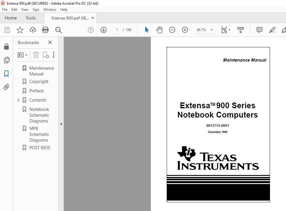
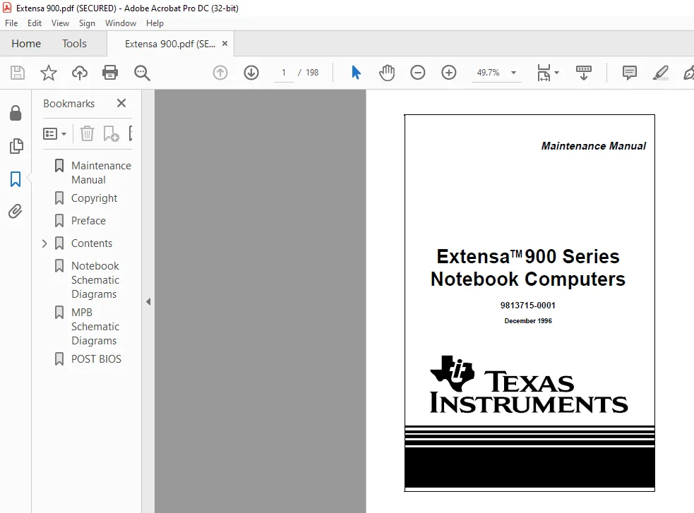
ExtensaTM 900 Series Notebook Computers Maintenance Manual – PDF DOWNLOAD
Original price was: $60.00.$15.95Current price is: $15.95.
ExtensaTM 900 Series Notebook Computers Maintenance Manual – PDF DOWNLOAD
Description
ExtensaTM 900 Series Notebook Computers Maintenance Manual – PDF DOWNLOAD


Preface
Introduction
This manual provides installation, operation and servicing data for the ExtensaTM 900
Series Notebook Computers.
Intended Audience
This manual is primarily intended for use by qualified service technicians but contains
information useful to non-technical users.
Contents
This manual contains six sections and one appendix that are common to all Extensa
900 Series Notebook Computers (differences described as they are covered):
¨ Section 1: General Description – Introduces the main features of the Extensa
900 Series Notebook Computers; identifies all options, provides physical and
electrical specifications.
¨ Section 2: Installation – Describes how to unpack, install options and begin
using the notebook.
¨ Section 3: Operating Instructions – Describes the notebook computer
operating controls and indicators and basic operating procedures required to
support maintenance operations.
¨ Section 4: Theory of Operation – Provides a block diagram level theory of
operation for the Extensa Series Notebooks.
¨ Section 5: Troubleshooting Procedures – Provides troubleshooting
procedures for the notebook computer series.
¨ Section 6: Field Service – Provides preventive and corrective maintenance
procedures for the notebook computer series including FRU removal/
replacement procedures.
¨ Appendix A: Notebook Schematic Diagrams – Provides schematic diagrams
for the Extensa 900 Series Notebook Computer.
¨ Appendix B: MPB Schematic Diagrams – Provides schematic diagrams for the
Extensa 900 Series Mobile Productivity Base.
ExtensaTM 900 Series Notebook Computers Maintenance Manual – PDF DOWNLOAD
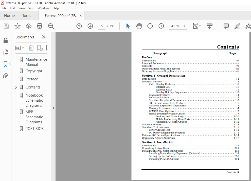
Paragraph Page
Preface
Introduction - - - - - - - - - - - - - - - - - - - - - - - - - - - - - - - - - - - - - - - - - - - - - - - - vii
Intended Audience- - - - - - - - - - - - - - - - - - - - - - - - - - - - - - - - - - - - - - - - - - - - vii
Contents - - - - - - - - - - - - - - - - - - - - - - - - - - - - - - - - - - - - - - - - - - - - - - - - - - vii
Other Manuals About the System- - - - - - - - - - - - - - - - - - - - - - - - - - - - - - - - - -viii
Ordering Parts and Supplies - - - - - - - - - - - - - - - - - - - - - - - - - - - - - - - - - - - - -viii
Section 1 General Description
Introduction - - - - - - - - - - - - - - - - - - - - - - - - - - - - - - - - - - - - - - - - - - - - - - 1-1
Product Overview - - - - - - - - - - - - - - - - - - - - - - - - - - - - - - - - - - - - - - - - - - - 1-1
Video Display Features - - - - - - - - - - - - - - - - - - - - - - - - - - - - - - - - - - - 1-3
Internal LCD - - - - - - - - - - - - - - - - - - - - - - - - - - - - - - - - - - - - - - 1-3
External CRTs - - - - - - - - - - - - - - - - - - - - - - - - - - - - - - - - - - - - - 1-3
Display Hot Key Sequences - - - - - - - - - - - - - - - - - - - - - - - - - - - - 1-3
Keyboard Features - - - - - - - - - - - - - - - - - - - - - - - - - - - - - - - - - - - - - - 1-4
Software Features - - - - - - - - - - - - - - - - - - - - - - - - - - - - - - - - - - - - - - - 1-4
Standard Peripheral Devices - - - - - - - - - - - - - - - - - - - - - - - - - - - - - - - - 1-5
900 Series Connectivity Features- - - - - - - - - - - - - - - - - - - - - - - - - - - - - 1-5
Notebook Expansion Capabilities- - - - - - - - - - - - - - - - - - - - - - - - - - - - - 1-7
Memory Expanson - - - - - - - - - - - - - - - - - - - - - - - - - - - - - - - - - - - - - - 1-7
PCMCIA Card Options - - - - - - - - - - - - - - - - - - - - - - - - - - - - - - - - - - - - 1-7
Mobile Productivity Base Option - - - - - - - - - - - - - - - - - - - - - - - - - - - - - 1-7
Docking and Undocking- - - - - - - - - - - - - - - - - - - - - - - - - - - - - - 1-10
Mobile Productivity Base Ports - - - - - - - - - - - - - - - - - - - - - - - - - 1-11
Advanced PCI Card Options - - - - - - - - - - - - - - - - - - - - - - - - - - - 1-12
Notebook Battery - - - - - - - - - - - - - - - - - - - - - - - - - - - - - - - - - - - - - - - - - - 1-12
Standard Test Features - - - - - - - - - - - - - - - - - - - - - - - - - - - - - - - - - - - - - - 1-12
Power On Self Test - - - - - - - - - - - - - - - - - - - - - - - - - - - - - - - - - - - - - 1-12
PC-Doctor Diagnostics Program- - - - - - - - - - - - - - - - - - - - - - - - - - - - - 1-13
Extensa 900 Series Specifications - - - - - - - - - - - - - - - - - - - - - - - - - - - - - - - 1-14
Regulatory Agency Approvals- - - - - - - - - - - - - - - - - - - - - - - - - - - - - - - - - - - 1-17
Section 2 Installation
Introduction - - - - - - - - - - - - - - - - - - - - - - - - - - - - - - - - - - - - - - - - - - - - - - - 2-1
Unpacking Instructions - - - - - - - - - - - - - - - - - - - - - - - - - - - - - - - - - - - - - - - 2-1
Installing Internal Notebook Options - - - - - - - - - - - - - - - - - - - - - - - - - - - - - - 2-2
Installing Main Memory Expansion (Optional) - - - - - - - - - - - - - - - - - - - - 2-2
Setting Up the Software - - - - - - - - - - - - - - - - - - - - - - - - - - - - - - - - - - - 2-3
Installing PCMCIA Options - - - - - - - - - - - - - - - - - - - - - - - - - - - - - - - - - 2-4
iv Contents
Contents (continued)
Paragraph Page
Section 2 Installation (continued)
Installing External Notebook Options - - - - - - - - - - - - - - - - - - - - - - - - - - - - - - 2-5
Installing the Mobile Productivity Base (Option) - - - - - - - - - - - - - - - - - - - 2-5
Docking the Notebook to the MPB - - - - - - - - - - - - - - - - - - - - - - - - 2-5
Cabling to the MPB - - - - - - - - - - - - - - - - - - - - - - - - - - - - - - - - - - 2-6
Installing Ext. Keyboard/Mouse/Numeric Keypad - - - - - - - - - - - - - - - - - 2-8
Installing an External Parallel Printer - - - - - - - - - - - - - - - - - - - - - - - - - - 2-9
Installing an External Serial Port Device - - - - - - - - - - - - - - - - - - - - - - - 2-10
Installing an External VGA Monitor - - - - - - - - - - - - - - - - - - - - - - - - - - 2-11
Primary Battery Pack Installation - - - - - - - - - - - - - - - - - - - - - - - - - - - - - - - - 2-13
Installing the AC Power Adapter - - - - - - - - - - - - - - - - - - - - - - - - - - - - - - - - 2-13
Initial Software Load - - - - - - - - - - - - - - - - - - - - - - - - - - - - - - - - - - - - - - - - 2-14
Section 3 Operating Instructions
Introduction - - - - - - - - - - - - - - - - - - - - - - - - - - - - - - - - - - - - - - - - - - - - - - 3-1
Controls/Indicators - - - - - - - - - - - - - - - - - - - - - - - - - - - - - - - - - - - - - - - - - - 3-1
Power On/Off Switch - - - - - - - - - - - - - - - - - - - - - - - - - - - - - - - - - - - - - 3-2
Notebook LEDs - - - - - - - - - - - - - - - - - - - - - - - - - - - - - - - - - - - - - - - - - 3-2
LED Icons - - - - - - - - - - - - - - - - - - - - - - - - - - - - - - - - - - - - - - - - - - - - 3-2
Keyboard Hot Key Sequences - - - - - - - - - - - - - - - - - - - - - - - - - - - - - - - 3-3
Windows 95 Special Keys - - - - - - - - - - - - - - - - - - - - - - - - - - - - - - 3-5
DOS Special Keys - - - - - - - - - - - - - - - - - - - - - - - - - - - - - - - - - - - 3-5
Configuring the Touchpad- - - - - - - - - - - - - - - - - - - - - - - - - - - - - - - - - - - - - - 3-6
Using a CD-ROM Drive (MPB Option Only - - - - - - - - - - - - - - - - - - - - - - - - - - - 3-6
Inserting a CD (MPB Option Only) - - - - - - - - - - - - - - - - - - - - - - - - - - - - 3-6
Handling CDs (MPB Option Only - - - - - - - - - - - - - - - - - - - - - - - - - - - - - 3-6
Built-In Sound System - - - - - - - - - - - - - - - - - - - - - - - - - - - - - - - - - - - - - - - - 3-7
Turning Sound On/Off- - - - - - - - - - - - - - - - - - - - - - - - - - - - - - - - - - - - 3-7
Sound Software - - - - - - - - - - - - - - - - - - - - - - - - - - - - - - - - - - - - - - - - 3-7
External Sound Equipment- - - - - - - - - - - - - - - - - - - - - - - - - - - - - - - - - 3-8
Using Remote Connections - - - - - - - - - - - - - - - - - - - - - - - - - - - - - - - - - - - - - 3-8
Using the Fast Infrared (FIR) Port- - - - - - - - - - - - - - - - - - - - - - - - - - - - - 3-8
Using Zoomed Video Features - - - - - - - - - - - - - - - - - - - - - - - - - - - - - - - - - - - 3-9
MPEG PC Card - - - - - - - - - - - - - - - - - - - - - - - - - - - - - - - - - - - - - - - - - 3-9
Battery Saving Tips - - - - - - - - - - - - - - - - - - - - - - - - - - - - - - - - - - - - - - - - - - 3-9
Lowering Inactivity Timeouts- - - - - - - - - - - - - - - - - - - - - - - - - - - - - - - - 3-9
Suspending Operation While Idle - - - - - - - - - - - - - - - - - - - - - - - - - - - - 3-10
Responding to a Low Battery Condition- - - - - - - - - - - - - - - - - - - - - - - - 3-10
Replacing the Battery- - - - - - - - - - - - - - - - - - - - - - - - - - - - - - - - - - - - 3-11
Saving to Disk - - - - - - - - - - - - - - - - - - - - - - - - - - - - - - - - - - - - - - - - 3-11
Contents v
Contents (continued)
Paragraph Page
Section 4 Theory of Operation
Introduction - - - - - - - - - - - - - - - - - - - - - - - - - - - - - - - - - - - - - - - - - - - - - - - 4-1
Notebook Functional Overview - - - - - - - - - - - - - - - - - - - - - - - - - - - - - - - - - - 4-1
System Processor - - - - - - - - - - - - - - - - - - - - - - - - - - - - - - - - - - - - - - - 4-3
Memory Subsystem- - - - - - - - - - - - - - - - - - - - - - - - - - - - - - - - - - - - - - 4-5
Main Memory- - - - - - - - - - - - - - - - - - - - - - - - - - - - - - - - - - - - - - 4-5
Flash ROM - - - - - - - - - - - - - - - - - - - - - - - - - - - - - - - - - - - - - - - 4-6
System Controller Function - - - - - - - - - - - - - - - - - - - - - - - - - - - - 4-6
ALI M1521 (Memory, Cache and DRAM Controller)- - - - - - - - - - - - - 4-8
ALI M1523 (PCA-ISA Bridge)- - - - - - - - - - - - - - - - - - - - - - - - - - - - 4-9
Video Subsystem - - - - - - - - - - - - - - - - - - - - - - - - - - - - - - - - - - - - - - -4-12
C&T 65550 Features- - - - - - - - - - - - - - - - - - - - - - - - - - - - - - - - -4-12
Versatile Panel Support - - - - - - - - - - - - - - - - - - - - - - - - - - - - - - -4-13
Low Power Consumption - - - - - - - - - - - - - - - - - - - - - - - - - - - - - -4-13
Software Compatibility/Flexibility - - - - - - - - - - - - - - - - - - - - - - - -4-13
Sound Subsystem- - - - - - - - - - - - - - - - - - - - - - - - - - - - - - - - - - - - - - -4-13
ESS1878 Audio Controller with Interface to Expansion Audio Mixer -4-13
ES1878 Features - - - - - - - - - - - - - - - - - - - - - - - - - - - - - - - - - - -4-14
Keyboard Subsystem- - - - - - - - - - - - - - - - - - - - - - - - - - - - - - - - - - - - -4-14
I/O Subsystem- - - - - - - - - - - - - - - - - - - - - - - - - - - - - - - - - - - - - - - - -4-14
NS87338VJG Super I/O Controller - - - - - - - - - - - - - - - - - - - - - - -4-14
Hard Disk Drive Subsystem - - - - - - - - - - - - - - - - - - - - - - - - - - - - - - - -4-17
PCI0643 Features- - - - - - - - - - - - - - - - - - - - - - - - - - - - - - - - - - -4-17
Floppy Disk Drive Subsystem - - - - - - - - - - - - - - - - - - - - - - - - - - - - - - -4-18
PCI 1130 Features - - - - - - - - - - - - - - - - - - - - - - - - - - - - - - - - - -4-19
PCMCIA Subsystem - - - - - - - - - - - - - - - - - - - - - - - - - - - - - - - - - - - - -4-18
Power Subsystem - - - - - - - - - - - - - - - - - - - - - - - - - - - - - - - - - - - - - - -4-20
ALI M6377 Power Management Unit - - - - - - - - - - - - - - - - - - - - - -4-22
AC Power Adapter- - - - - - - - - - - - - - - - - - - - - - - - - - - - - - - - - - -4-25
Mobile Productivity Base Interface - - - - - - - - - - - - - - - - - - - - - - - - - - - -4-25
Section 5 Troubleshooting Procedures
Introduction - - - - - - - - - - - - - - - - - - - - - - - - - - - - - - - - - - - - - - - - - - - - - - - 5-1
Overview of Fault Isolation Process - - - - - - - - - - - - - - - - - - - - - - - - - - - - - - - 5-1
Troubleshooting Procedures - - - - - - - - - - - - - - - - - - - - - - - - - - - - - - - - - - - - 5-3
Troubleshooting a Power Supply Problem - - - - - - - - - - - - - - - - - - - - - - - 5-3
Troubleshooting a Display Problem - - - - - - - - - - - - - - - - - - - - - - - - - - - 5-3
Fault Isolation Using Power On Self Test- - - - - - - - - - - - - - - - - - - - - - - - 5-4
POST Error Messages - - - - - - - - - - - - - - - - - - - - - - - - - - - - - - - - 5-5
POST Beep Error Messages - - - - - - - - - - - - - - - - - - - - - - - - - - - - 5-8
Run-Time Error Messages - - - - - - - - - - - - - - - - - - - - - - - - - - - - - - - - - 5-9
PCMCIA Modem Problems - - - - - - - - - - - - - - - - - - - - - - - - - - - - - - - - -5-10
vi Contents
Contents (continued)
Paragraph Page
Section 6 Troubleshootig Procedures (continued)
General Fault Isolation Procedures - - - - - - - - - - - - - - - - - - - - - - - - - - - - - - - 5-12
Fault Isolation Using Diagnostics - - - - - - - - - - - - - - - - - - - - - - - - - - - - - - - - 5-13
PC-Doctor (In DOS Mode or DOS Windows) - - - - - - - - - - - - - - - - - - - - - 5-13
Supporting Online Documentation - - - - - - - - - - - - - - - - - - - - - - - - - - - 5-15
User Interface to PC-Doctor - - - - - - - - - - - - - - - - - - - - - - - - - - - - - - - 5-15
Quitting PC-Doctor - - - - - - - - - - - - - - - - - - - - - - - - - - - - - - - - - - - - - 5-15
Section 6 Field Service
Introduction - - - - - - - - - - - - - - - - - - - - - - - - - - - - - - - - - - - - - - - - - - - - - - - 6-1
Preventive Maintenance - - - - - - - - - - - - - - - - - - - - - - - - - - - - - - - - - - - - - - - 6-1
Cleaning the Computer - - - - - - - - - - - - - - - - - - - - - - - - - - - - - - - - - - - 6-1
Handling the Computer - - - - - - - - - - - - - - - - - - - - - - - - - - - - - - - - - - - 6-2
Handling the Computer Battery Pack - - - - - - - - - - - - - - - - - - - - - - - - - - 6-2
Password Caution - - - - - - - - - - - - - - - - - - - - - - - - - - - - - - - - - - - - - - - 6-3
Required Tools and Equipment - - - - - - - - - - - - - - - - - - - - - - - - - - - - - - - - - - 6-3
Notebook FRUs - - - - - - - - - - - - - - - - - - - - - - - - - - - - - - - - - - - - - - - - - - - - - 6-3
Cover-Display Assembly - - - - - - - - - - - - - - - - - - - - - - - - - - - - - - - - - - - 6-4
System Base Assembly- - - - - - - - - - - - - - - - - - - - - - - - - - - - - - - - - - - - 6-6
Mobile Productivity Base Assembly - - - - - - - - - - - - - - - - - - - - - - - - - - - 6-9
Notebook FRU Replacement Procedures - - - - - - - - - - - - - - - - - - - - - - - - - - - 6-10
Removing/Replacing the Notebook Battery Pack- - - - - - - - - - - - - - - - - - 6-11
Removing/Replacing PCMCIA Options - - - - - - - - - - - - - - - - - - - - - - - - 6-12
Installing/Removing the Mobile Productivity Base- - - - - - - - - - - - - - - - - 6-13
Removing/Replacing the Hard Disk Drive Assembly - - - - - - - - - - - - - - - 6-15
Removing/Replacing the Keyboard Assembly - - - - - - - - - - - - - - - - - - - - 6-16
Heat Sink Assembly Removal/Replacement - - - - - - - - - - - - - - - - - - - - - 6-17
Display Assembly Removal/Replacement - - - - - - - - - - - - - - - - - - - - - - 6-18
Removing/Replacing the LED/Microphone Board Assembly - - - - - - - - - - 6-19
Removing/Replacing the CPU Board- - - - - - - - - - - - - - - - - - - - - - - - - - 6-20
Removing/Replacing the Top Cover - - - - - - - - - - - - - - - - - - - - - - - - - - 6-21
Removing/Replacing the VGA Video Board - - - - - - - - - - - - - - - - - - - - - 6-23
Removing/Replacing the Power Supply Board - - - - - - - - - - - - - - - - - - - 6-24
Removing/Replacing the DC-In Board Assembly- - - - - - - - - - - - - - - - - - 6-25
Removng/Replacing the PC Card Module - - - - - - - - - - - - - - - - - - - - - - 6-26
Removing/Replacing the Main Board Assembly - - - - - - - - - - - - - - - - - - 6-27
Removing Touchpad and Speakers- - - - - - - - - - - - - - - - - - - - - - - - - - - 6-28
Removing/Replacing the Display Bezel - - - - - - - - - - - - - - - - - - - - - - - - 6-29
Removing/Replacing the LCD - - - - - - - - - - - - - - - - - - - - - - - - - - - - - - 6-30
Removing/Replacing the Display Inverter Boards - - - - - - - - - - - - - - - - - 6-31
Removing/Repalcing MPB FRUs- - - - - - - - - - - - - - - - - - - - - - - - - - - - - - - - - 6-32
Removing/Replacing the Media Bay Device - - - - - - - - - - - - - - - - - - - - - 6-32
Content
PLEASE NOTE:
- This is the SAME exact manual used by your dealers to fix your vehicle.
- The same can be yours in the next 2-3 mins as you will be directed to the download page immediately after paying for the manual.
- Any queries / doubts regarding your purchase, please feel free to contact [email protected]
s.m