EZGO Club Car Golf Cart Gasoline Powered Golf Cars Repair & Service Manual 605586 – PDF DOWNLOAD
$35.95
EZGO Club Car Golf Cart Gasoline Powered Golf Cars Repair & Service Manual 605586 – PDF DOWNLOAD
Description
EZGO Club Car Golf Cart Gasoline Powered Golf Cars Repair & Service Manual 605586 – PDF DOWNLOAD
FILE DETAILS:
EZGO Club Car Golf Cart Gasoline Powered Golf Cars Repair & Service Manual 605586 – PDF DOWNLOAD
Language : English
Pages : 1770
Downloadable : Yes
File Type : PDF
DESCRIPTION:
EZGO Club Car Golf Cart Gasoline Powered Golf Cars Repair & Service Manual 605586 – PDF DOWNLOAD
SAFETY:
- For any questions on material contained in this manual, contact an authorized representative for clarification.
- Read and understand all labels located on the vehicle. Always replace any damaged or missing labels.
On steep hills it is possible for vehicles to coast at greater than normal speeds encountered on a flat surface. To prevent loss of vehicle control and possible serious injury, speeds should be limited to no more than the maximum speed on level ground. See GENERAL SPECIFICATIONS. Limit speed by applying the service brake. - Catastrophic damage to the drivetrain components due to excessive speed may result from driving the vehicle above
specified speed. Damage caused by excessive speed may cause a loss of vehicle control, is costly, is considered
abuse and will not be covered under warranty. - For towing/transporting vehicle, refer to “TRANSPORTING VEHICLE”.
Signs similar to the ones illustrated should be used to warn of situations that could result in an unsafe condition.
SAFETY INFORMATION:
This manual has been designed to assist in maintaining the vehicle in accordance with procedures developed by the
manufacturer. Adherence to these procedures and troubleshooting tips will ensure the best possible service from the
product. To reduce the chance of personal injury or property damage, the following must be carefully observed:
GENERAL:
- Many vehicles are used for a variety of tasks beyond the original intended use of the vehicle; therefore, it is impossible
to anticipate and warn against every possible combination of circumstances that may occur. No warnings can take the
place of good common sense and prudent driving practices. - Good common sense and prudent driving practices do more to prevent accidents and injury than all of the warnings
and instructions combined. The manufacturer strongly suggests that all users and maintenance personnel read this
entire manual paying particular attention to the CAUTIONS and WARNINGS contained therein. - If you have any questions regarding this vehicle, contact your closest representative or write to the address on the
back cover of this publication, Attention: Product Service Department. - The manufacturer reserves the right to make design changes without obligation to make these changes on units previously sold and the information contained in this manual is subject to change without notice.
- The manufacturer is not liable for errors in this manual or for incidental or consequential damages that result from the use of the material in this manual.
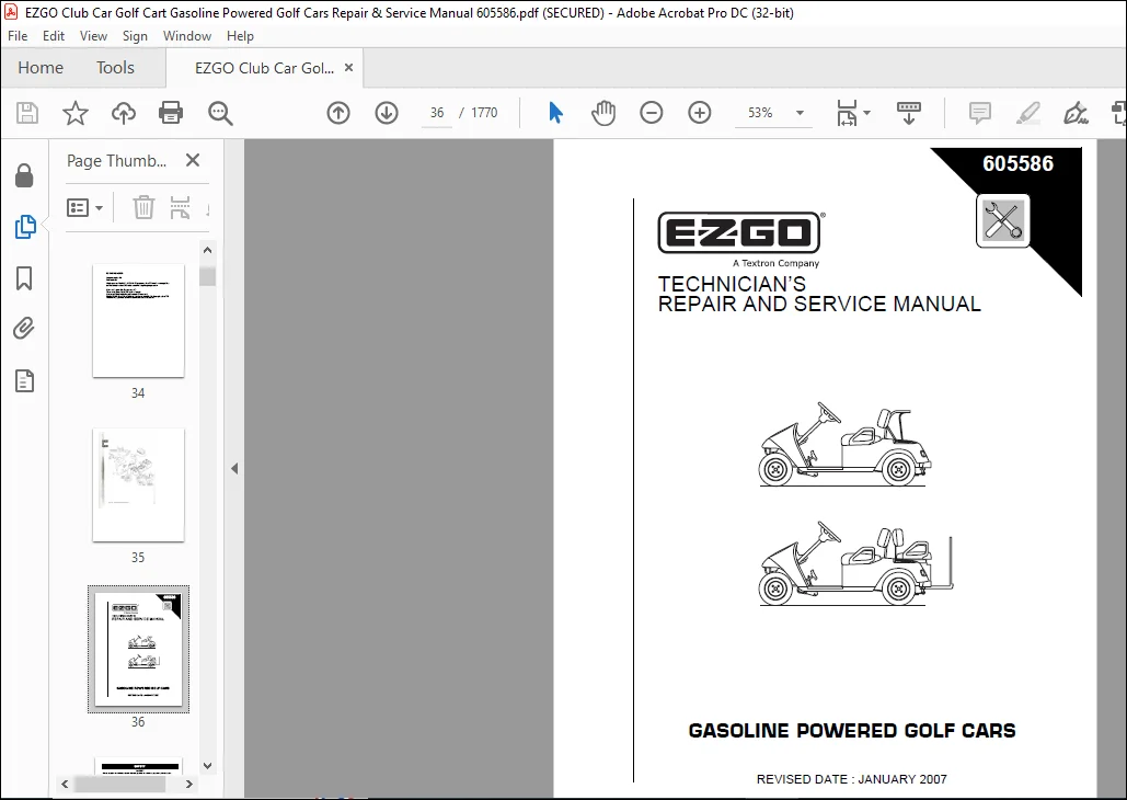
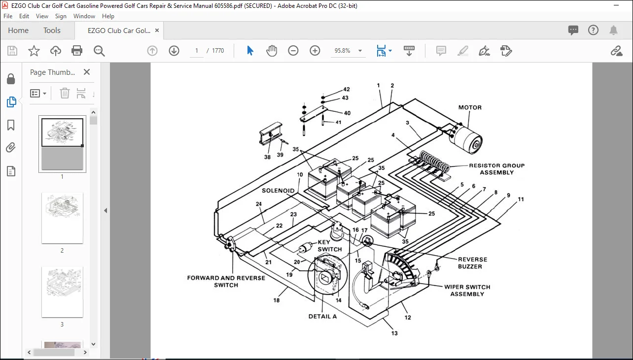
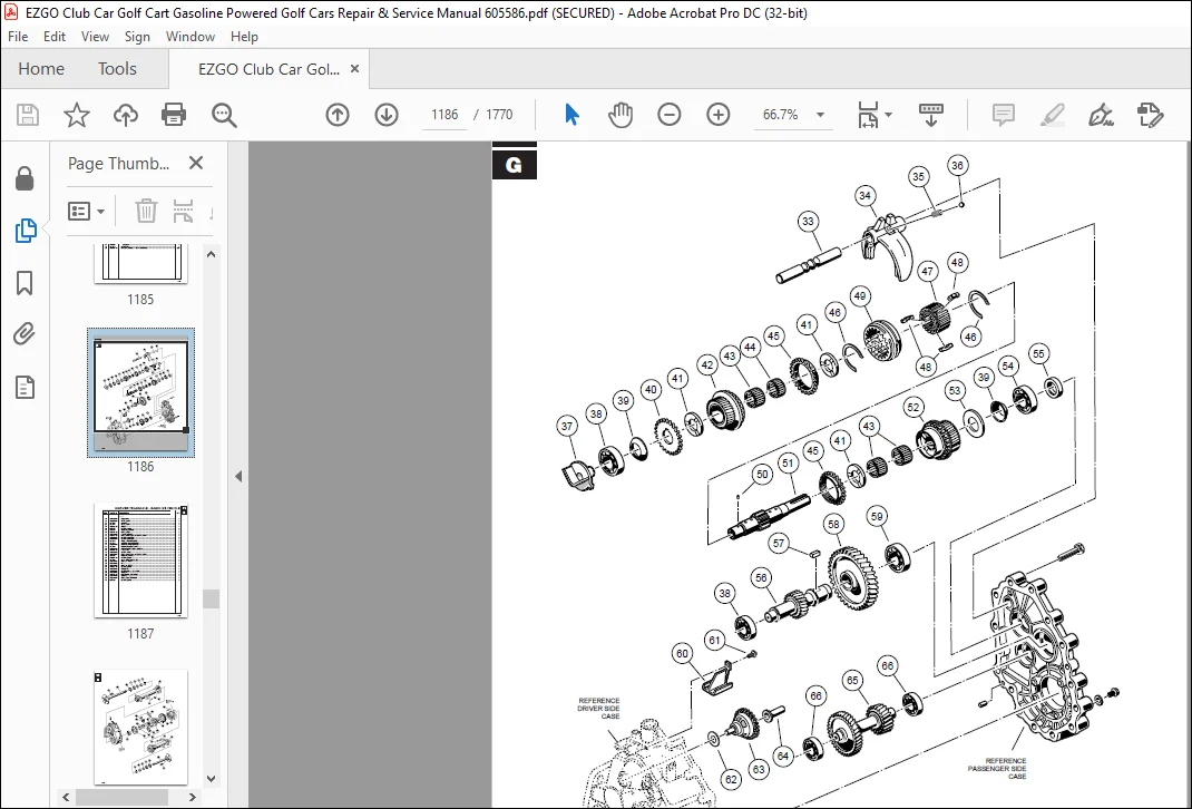
IMAGES PREVIEW OF THE MANUAL:
TABLE OF CONTENTS:
EZGO Club Car Golf Cart Gasoline Powered Golf Cars Repair & Service Manual 605586 – PDF DOWNLOAD
1984-2008 CLUB CAR GOLF CARTS..................................................................................................................................................................................................................................................................... 36 ELECTRICAL.................................................................................................................................................................................................................................................................................... 1 ELECTRIC CLUB............................................................................................................................................................................................................................................................................. 1 1981-85 WIRING............................................................................................................................................................................................................................................................................ 2 1989-03 16 WIRING......................................................................................................................................................................................................................................................................... 3 1996 48V WIRING........................................................................................................................................................................................................................................................................... 4 2004 PRECEDENT WIRING..................................................................................................................................................................................................................................................................... 5 36V GLIDE................................................................................................................................................................................................................................................................................. 6 48V REGEN................................................................................................................................................................................................................................................................................. 7 95-03 48V WIRING.......................................................................................................................................................................................................................................................................... 8 BATTERY BREAK IN.......................................................................................................................................................................................................................................................................... 9 BATTERY CHARGE AND LIFE................................................................................................................................................................................................................................................................... 10 CLUB CAR 36V WIRING....................................................................................................................................................................................................................................................................... 11 CLUB CAR 48V REGEN WIRING................................................................................................................................................................................................................................................................. 12 CLUB CAR 48V WIRING....................................................................................................................................................................................................................................................................... 16 CLUB CAR 5 SOLENOID....................................................................................................................................................................................................................................................................... 20 CLUB CAR GAS WIRING 92-96................................................................................................................................................................................................................................................................. 21 DEEP CYCLE MAINTENANCE.................................................................................................................................................................................................................................................................... 23 BATTERY MAINTENANCE....................................................................................................................................................................................................................................................................... 31 GOLF CART BATTERY MAINTENANCE............................................................................................................................................................................................................................................................. 32 RE-WIRING MOTOR........................................................................................................................................................................................................................................................................... 34 SIMPLE HEADLIGHT TAILIGHT WIRING.......................................................................................................................................................................................................................................................... 35 MECHANICAL.................................................................................................................................................................................................................................................................................... 36 2007 TECHNICIAN’S REPAIR AND SERVICE MANUAL............................................................................................................................................................................................................................................... 36 REVISED DATE : JANUARY 2007........................................................................................................................................................................................................................................................... 36 GASOLINE POWERED GOLF CARS............................................................................................................................................................................................................................................................ 36 TECHNICIAN’S...................................................................................................................................................................................................................................................................... 36 REPAIR AND SERVICE MANUAL......................................................................................................................................................................................................................................................... 36 SAFETY........................................................................................................................................................................................................................................................................ 37 TECHNICIAN’S...................................................................................................................................................................................................................................................................... 38 REPAIR AND SERVICE MANUAL......................................................................................................................................................................................................................................................... 38 GASOLINE POWERED TXT GOLF CARS & PERSONAL VEHICLES............................................................................................................................................................................................................................ 38 FLEET GOLF CAR (9 hp, CE, CARB)........................................................................................................................................................................................................................................... 38 FREEDOM™ (9 hp, CE, CARB, SE, LE, HP)..................................................................................................................................................................................................................................... 38 SHUTTLE 2 + 2 ( 9 hp, CE, CARB)........................................................................................................................................................................................................................................... 38 BATTERY PROLONGED STORAGE......................................................................................................................................................................................................................................................... 39 TITLE SECTION..................................................................................................................................................................................................................................................................... 40 SAFETY INFORMATION............................................................................................................................................................................................................................................................ 42 SERIAL NUMBER PLATE AND LOCATION...................................................................................................................................................................................................................................................... 48 Fig. 1 Serial Number Plate Location............................................................................................................................................................................................................................................... 48 STARTING THE VEHICLE WITH A DISCHARGED BATTERY........................................................................................................................................................................................................................................ 48 SERVICING THE VEHICLE................................................................................................................................................................................................................................................................. 48 Fig. 2 Initial Service Chart...................................................................................................................................................................................................................................................... 49 TOWING................................................................................................................................................................................................................................................................................ 49 Fig. 3 Neutral Lock (Direction Selector).......................................................................................................................................................................................................................................... 50 ROUTINE MAINTENANCE................................................................................................................................................................................................................................................................... 50 Some maintenance items must be serviced more frequently on vehicles used under severe driving conditions.......................................................................................................................................................................... 50 Fig. 4 Lubrication Points......................................................................................................................................................................................................................................................... 50 POWERTRAIN MAINTENANCE................................................................................................................................................................................................................................................................ 50 BRAKES................................................................................................................................................................................................................................................................................ 50 Over time, a subtle loss of performance may take place. Therefore, it is important to establish the standard with a new vehicle................................................................................................................................................... 50 TIRES................................................................................................................................................................................................................................................................................. 50 CARE AND CLEANING OF THE VEHICLE...................................................................................................................................................................................................................................................... 51 If the engine does not start or runs improperly after washing, remove the spark plug wires (by pulling the spark plug boots, never the wires) and blow them dry. Reinstall the wires. Remove moisture from coil by blowing across top............................................. 51 VEHICLE CARE PRODUCTS................................................................................................................................................................................................................................................................. 51 TOP AND WINDSHIELD.................................................................................................................................................................................................................................................................... 51 TRAILERING............................................................................................................................................................................................................................................................................ 52 WINTER OR PROLONGED STORAGE........................................................................................................................................................................................................................................................... 52 HARDWARE.............................................................................................................................................................................................................................................................................. 52 Fig. 5 Bolt Grades................................................................................................................................................................................................................................................................ 52 TORQUE SPECIFICATIONS................................................................................................................................................................................................................................................................. 52 Fig. 6 Torque Specifications...................................................................................................................................................................................................................................................... 52 PERIODIC SERVICE SCHEDULE............................................................................................................................................................................................................................................................. 53 Fig. 7 Periodic Service Schedule.................................................................................................................................................................................................................................................. 53 PART II FOR THE USER.......................................................................................................................................................................................................................................................... 58 4 GENERAL SAFETY PRACTICES.................................................................................................................................................................................................................................................... 58 4.1 Introduction.......................................................................................................................................................................................................................................................... 58 4.2 Stability............................................................................................................................................................................................................................................................. 58 (a) The user shall train carrier operators to adhere strictly to the operating instructions stated in this Standard....................................................................................................................................................... 58 (b) The user shall survey specific operating conditions and environment, and establish and train carrier operators to comply with additional, specific safety practices................................................................................................... 58 4.3 Nameplates, Markings, Capacity, and Modifications................................................................................................................................................................................................................. 58 4.4 Fuel Handling and Storage......................................................................................................................................................................................................................................... 58 4.5 Changing and Charging Storage Batteries for Electric Personnel and Burden Carriers................................................................................................................................................................................ 58 NOTES, CAUTIONS AND WARNINGS.................................................................................................................................................................................................................................................. 68 A NOTE indicates a condition that should be observed...................................................................................................................................................................................................................... 68 IMPORTANT SAFETY WARNING...................................................................................................................................................................................................................................................... 68 MODIFICATIONS TO VEHICLE...................................................................................................................................................................................................................................................... 68 GENERAL MAINTENANCE........................................................................................................................................................................................................................................................... 68 BEFORE SERVICING THE VEHICLE.................................................................................................................................................................................................................................................. 68 Battery Removal and Installation.......................................................................................................................................................................................................................................... 69 In the following text, there are references to removing/installing bolts etc. Additional hardware (nuts, washers, etc.) that is ...................................................................................................................................... 69 Fig. 1 Battery Removal............................................................................................................................................................................................................................................ 70 LIFTING THE VEHICLE........................................................................................................................................................................................................................................................... 70 Fig. 2 Lifting the vehicle................................................................................................................................................................................................................................................ 70 4.1 Hazardous Locations............................................................................................................................................................................................................................................... 59 4.2 Lighting for Operating Areas...................................................................................................................................................................................................................................... 59 4.3 Control of Noxious Gases and Fumes................................................................................................................................................................................................................................ 59 4.4 Warning Device(s)................................................................................................................................................................................................................................................. 59 1 OPERATING SAFETY RULES AND PRACTICES.................................................................................................................................................................................................................................... 59 5.1 Personnel and Burden Carrier Operator Qualifications.............................................................................................................................................................................................................. 59 5.2 Personnel and Burden Carrier Operators’ Training.................................................................................................................................................................................................................. 59 (a) instructional material provided by the manufacturer;.............................................................................................................................................................................................................. 59 (b) emphasis on safety of passengers, material loads, carrier operator, and other employees;.......................................................................................................................................................................... 59 (c) general safety rules contained within this Standard and the additional specific rules determined by the user in accordance with this Standard, and why they were formulated;...................................................................................... 59 (d) introduction of equipment, control locations and functions, and explanation of how they work when used properly and when used improperly, and surface conditions, grade, and other conditions of the environment in which the carrier is to be operated;.......... 59 (a) operational performance tests and evaluations during, and at completion of, the program........................................................................................................................................................................... 60 5.1 Personnel and Burden Carrier Operator Responsibility.......................................................................................................................................................................................................... 60 5.2 General....................................................................................................................................................................................................................................................... 60 5.3 Traveling..................................................................................................................................................................................................................................................... 60 5.1 Loading....................................................................................................................................................................................................................................................... 61 5.2 Operator Care of Personnel and Burden Carriers................................................................................................................................................................................................................ 61 1 MAINTENANCE PRACTICES................................................................................................................................................................................................................................................... 61 6.1 Introduction...................................................................................................................................................................................................................................................... 61 6.1.1 Carriers may become hazardous if maintenance is neglected. Therefore, maintenance facilities, trained personnel, and procedures shall be provided. Such facilities may be on or off the premises................................................................ 61 6.2 Maintenance Procedures........................................................................................................................................................................................................................................ 61 6.2.1 Maintenance and inspection of all carriers shall be performed in conformance with the manufacturer’s recommendations and the following practices................................................................................................................ 61 (a) A scheduled preventive maintenance, lubrication, and inspection system shall be followed...................................................................................................................................................................... 61 (b) Only qualified and authorized personnel shall be permitted to maintain, repair, adjust, and inspect carriers.................................................................................................................................................. 61 (c) Before undertaking maintenance or repair, follow the manufacturer’s recommendations for immobilizing the carrier.............................................................................................................................................. 61 (d) Block chassis before working underneath it.................................................................................................................................................................................................................... 61 (e) Before disconnecting any part of the engine fuel system of a gasoline or diesel powered carrier with gravity feed fuel systems, be sure shutoff valve is closed, and run engine until fuel system is depleted and engine stops running........................ 61 (a) Before disconnecting any part of the engine fuel system of LP gas powered carriers, close the LP gas cylinder valve and run the engine until fuel in the system is depleted and the engine stops running...................................................... 62 (b) Operation to check performance of the carrier shall be conducted in an authorized area where safe clearance exists............................................................................................................................................ 62 (c) Before commencing operation of the carrier, follow the manufacturer’s instructions and recommended procedures................................................................................................................................................. 62 (d) Avoid fire hazards and have fire protection equipment present in the work area. Do not use an open flame to check level or leakage of fuel, battery electrolyte, or coolant. Do not use open pans of fuel or flammable cleaning fluids for cleaning parts..... 62 (e) Properly ventilate the work area.............................................................................................................................................................................................................................. 62 (f) Handle LP gas cylinders with care. Physical damage, such as dents, scrapes, or gouges, may dangerously weaken the tank and make it unsafe for use............................................................................................................. 62 (g) Brakes, steering mechanisms, speed and directional control mechanisms, warning devices, lights, governors, guards, and safety devices shall be inspected regularly and maintained in a safe operating condition............................................... 62 (h) Special carriers or devices designed and approved for hazardous area operation shall be inspected to ensure that maintenance preserves the original approved safe operating features.......................................................................... 62 (i) Fuel systems shall be checked for leaks and condition of parts. If a leak is found, action shall be taken to prevent the use of the carrier until the leak has been eliminated................................................................................ 62 (j) The carrier manufacturer’s capacity, operation, and maintenance instruction plates, tags, or decals shall be maintained in legible condition.................................................................................................................. 62 (k) Batteries, motors, speed and directional controllers, limit switches, protective devices, electrical conductors, and connections shall be inspected and maintained............................................................................................ 62 (l) Carriers shall be kept in a clean condition to minimize fire hazards and facilitate detection of loose or defective parts..................................................................................................................................... 62 (m) Modifications and additions which affect capacity and safe machine operation shall not be performed by the customer or user .................................................................................................................................. 62 (n) Care shall be taken to ensure that all replacement parts are interchangeable with the original parts and of a quality at least equal to that provided in the original equipment............................................................................... 62 END OF ASME/ANSI B56.8-2006........................................................................................................................................................................................................................................... 62 PART II: MAINTENANCE AND OPERATIONS................................................................................................................................................................................................................................... 64 5 General safety practices................................................................................................................................................................................................................................................ 64 5.1 Introduction...................................................................................................................................................................................................................................................... 64 5.2 Safety survey..................................................................................................................................................................................................................................................... 64 6 Maintenance............................................................................................................................................................................................................................................................. 65 6.1 Introduction...................................................................................................................................................................................................................................................... 65 1 Fuels handling and storage/battery charging............................................................................................................................................................................................................................. 66 7.1 Ventilation....................................................................................................................................................................................................................................................... 66 7.2 The controlling party shall require battery changing and charging facilities and procedures to be in accordance with applicable ordinances or regulations......................................................................................................... 66 7.3 The controlling party shall supervise the storage and handling of liquid fuels in accordance with ANSI/NFPA 30.................................................................................................................................................... 66 7.4 Storage and handling of liquefied petroleum gas fuels shall be in accordance with ANSI/NFPA 58.................................................................................................................................................................... 66 7.5 The controlling party shall periodically inspect charging and storage areas or facilities and review procedures to be certain that the procedures in 7.1 through 7.4, inclusive, are being followed............................................................... 66 8 Operating safety rules and practices (Operator qualifications).......................................................................................................................................................................................................... 66 8.1 It is recommended that only persons qualified under the rules of the regulatory authority be allowed to operate a golf car. Qualifications may include proof of insurance, minimum age requirement or other appropriate requirements.............................. 66 8.2 The controlling party shall display the operation and safety instructions as recommended by the golf car manufacturers and t...................................................................................................................................... 66 END OF ANSI/NGCMA Z130.1-2004......................................................................................................................................................................................................................................... 66 BODY...................................................................................................................................................................................................................................................................... 74 In the following text, there are references to removing/installing bolts etc. Additional hardware (nuts, washers etc.) that are ...................................................................................................................................... 74 General............................................................................................................................................................................................................................................................................... 74 Fig. 1 Drill Out Metal Rivet...................................................................................................................................................................................................................................................... 74 BODY COMPONENT REPLACEMENT.................................................................................................................................................................................................................................................... 74 Instrument Panel Replacement.......................................................................................................................................................................................................................................................... 74 The instrument panel may be removed without removing the cowl or may be removed as part of the cowl............................................................................................................................................................................... 74 Fig. 2 Body Components (Front).................................................................................................................................................................................................................................................... 75 Fig. 3 Body Components (Rear)..................................................................................................................................................................................................................................................... 76 Fig. 4 Shuttle 2 + 2 Components................................................................................................................................................................................................................................................... 77 Cowl Replacement...................................................................................................................................................................................................................................................................... 78 Front Shield Replacement.............................................................................................................................................................................................................................................................. 78 Rocker Panel Replacement.............................................................................................................................................................................................................................................................. 78 Body Replacement...................................................................................................................................................................................................................................................................... 79 Prior to removing the rear body, the foot rest or cargo bed, as applicable, must be removed. See the applicable paragraphs for instructions for replacement of those items........................................................................................................ 79 Shuttle 2+2 Component Replacement..................................................................................................................................................................................................................................................... 79 To avoid damage to the plastic body component, remove or install seat support brackets by sliding to the open end of the molded channel. Do not force the seat support brackets into or out of the channels from above............................................................ 79 Rear Bumper Replacement............................................................................................................................................................................................................................................................... 80 WHEEL AND TIRE SERVICE............................................................................................................................................................................................................................................................ 84 Tire Repair................................................................................................................................................................................................................................................................... 84 Tire plug tools and plugs are available at most automotive parts outlets and have the advantage of not requiring the tire be removed from the wheel....................................................................................................................... 84 Wheel Installation............................................................................................................................................................................................................................................................ 84 It is important to follow the ‘cross sequence’ pattern when installing lug nuts. This will assure even seating of the wheel against the hub............................................................................................................................... 85 Fig. 1 Wheels and Tires............................................................................................................................................................................................................................................................... 85 Fig. 1 Steering and Front Suspension.............................................................................................................................................................................................................................................. 88 MAINTENANCE................................................................................................................................................................................................................................................................... 89 In the following text, there are references to removing/installing bolts etc. Additional hardware (nuts, washers etc.) that is r.......................................................................................................................................... 89 Routine maintenance of the front suspension and steering consists of:................................................................................................................................................................................................................. 89 See Lubrication Chart and Periodic Service Schedule in Section A. Be sure to use only the recommended lubricants. Maintain the c...................................................................................................................................................... 89 Lubrication....................................................................................................................................................................................................................................................................... 89 Grease the rack ball joint (1) (Ref. Fig. 2 on Page E-2) per Periodic Service Schedule in Section A. Wipe off old grease that is forced out of rubber boot............................................................................................................................ 89 Fig. 2 Lubrication Points......................................................................................................................................................................................................................................................... 89 Wheel Bearing and King Pin Bushing Inspection..................................................................................................................................................................................................................................... 89 Lift the front of the vehicle and support on jack stands as per SAFETY section. Rotate the front wheel and feel for any roughness. While holding spindle with one hand, grasp bottom of tire with other hand and rock tire back and forth on spindle.................................. 89 Some minor rocking movement of tire is normal..................................................................................................................................................................................................................................... 89 If excess movement is detected, the wheel bearing may require repacking and adjusting or replacement. “Wheel Bearing Packing” on Page E-2) “Wheel Bearing Adjustment” on Page E-3).................................................................................................... 89 If the wheel bearing is satisfactory, a worn spindle bearing, which is not a serviceable item, is indicated and the spindle must be replaced. “Spindle Replacement” on Page E-12)..................................................................................................... 89 Wheel Bearing Packing............................................................................................................................................................................................................................................................. 89 Remove hub from spindle and disassemble. “Wheel Bearing and Race Replacement” on Page E-8)............................................................................................................................................................................................ 89 Clean all bearings, grease seal, hub and dust cap in solvent and dry thoroughly. Inspect for signs of damage. Pitting or a blue ...................................................................................................................................................... 89 The front wheel bearings are tapered roller type and must be packed with grease at installation or any time the bearing is remov...................................................................................................................................................... 89 Assemble hub and install on spindle. “Hub Replacement” on Page E-7)................................................................................................................................................................................................................... 90 Once hub is placed onto spindle and before outer wheel bearing is installed, fill the area between the inner and outer wheel bearings about 1/2 - 3/4 full with grease............................................................................................................ 90 Wheel Bearing Adjustment.......................................................................................................................................................................................................................................................... 90 If performing a wheel bearing adjustment only, lift and support front of vehicle per SAFETY section. Remove dust cap (1) and cotter pin (2) and loosen castellated nut (3)............................................................................................................ 90 If performing a wheel bearing adjustment as part of another procedure, make sure wheel is mounted to hub hand tight with lug nuts (4) and hub is loosely retained on spindle (5) with castellated nut (Ref. Fig. 3 on Page E-3)....................................................... 90 Seat bearings by rotating wheel while tightening castellated nut until slight resistance is felt...................................................................................................................................................................................... 90 Rotate the wheel 2 - 3 more turns to displace excess grease. If required, tighten castellated nut (3) again until slight resista...................................................................................................................................................... 90 Check for smooth and free rotation of the wheel and an absence of play when the wheel is grasped by the outside of the tire. Bend the cotter pin (2) against the flats of the castellated nut (3)..................................................................................... 90 Replace the dust cap (1) and lower vehicle per SAFETY section......................................................................................................................................................................................................................... 90 If completing a wheel bearing adjustment as part of another procedure, tighten front wheels per WHEELS AND TIRES section.............................................................................................................................................................. 90 Fig. 3 Bearing Adjustment......................................................................................................................................................................................................................................................... 90 Wheel Alignment................................................................................................................................................................................................................................................................... 90 Lift the front of the vehicle and support on jack stands as per SAFETY section. Confirm the alignment of the front springs. “Front Spring Replacement” on Page E-6)................................................................................................................... 90 Rotate each wheel and scribe a chalk line around the circumference of the tire at the center of the tread pattern. Lower vehicle...................................................................................................................................................... 90 Measure the distance between the chalk lines at both the front and rear of the tires (Ref. Fig. 4 on Page E-4). The measurement taken at the front of the tires should be 0" - 1/8" (0 - 3 mm) less than the rear..................................................................... 90 Fig. 4 Wheel Alignment............................................................................................................................................................................................................................................................ 91 To hold threaded tube while loosening jam nut, use a wrench on the center, flat section of tube............................................................................................................................................................................... 91 The tie rod has different threads on each end. The end with the groove in the threaded tube has left hand threads while the end without the groove has conventional right hand threads........................................................................................ 91 To adjust wheel alignment, loosen tie rod jam nuts (1) and turn tie rod (2) until correct alignment is achieved. Tighten jam nuts to 36 - 40 ft. lbs. (49 - 54 Nm) torque............................................................................................................. 91 Test drive vehicle and confirm steering wheel is correctly centered. If it is not centered, disconnect intermediate shaft from s...................................................................................................................................................... 91 Fig. 5 Disconnect Intermediate Shaft to Center Steering Wheel..................................................................................................................................................................................................................... 91 FRONT SUSPENSION.............................................................................................................................................................................................................................................................. 92 Fig. 6 Front Suspension Components................................................................................................................................................................................................................................................ 92 Front Shock Absorber Replacement.................................................................................................................................................................................................................................................. 92 Remove the nut (1) from the bottom of the shock absorber(2) at the front axle (3)(Ref. Fig. 6 on Page E-5)............................................................................................................................................................................ 92 Compress shock absorber to clear the mounting bracket................................................................................................................................................................................................................................. 92 Loosen the nut securing the top of the shock absorber to the vehicle frame and then rotate the shock absorber while holding the nut in place with a wrench............................................................................................................................ 92 Remove the shock absorber............................................................................................................................................................................................................................................................. 92 Installation of shock absorber is reverse of disassembly. Mounting nuts should be tightened until rubber bushings (4) expand to diameter of shock absorber washers (5)................................................................................................................ 92 Front Axle Replacement............................................................................................................................................................................................................................................................ 93 Loosen front wheels. Lift and support front of vehicle per SAFETY section and remove front wheels..................................................................................................................................................................................... 93 Remove hardware (1, 4, 5) securing shock absorbers (2) to front axle (3) (Ref. Fig. 6 on Page E-5).................................................................................................................................................................................... 93 On the driver side, remove lock nut (6) and washer (8) from bolt (7) and discard nut. Pull bolt (7) and washer (9) from spindle ...................................................................................................................................................... 93 Repeat at passenger side letting rack ball joint (29) rest on front spring to support spindle......................................................................................................................................................................................... 93 The intermediate shaft is assembled with the universal joints set 90 out of phase with each other................................................................................................................................................................................ 93 Remove hardware (13 - 15) securing rack and pinion unit (16) to front axle and discard lock nuts (15). Move rack and pinion unit...................................................................................................................................................... 93 Remove the three 1 3/4" long bolts (18), two 1 1/2" long bolts (28), spring plate (24) and five lock nuts (19) securing axle to springs and discard lock nuts......................................................................................................................... 93 At the 3 1/2" long bolt (20) securing front of left spring, note location of washer (22) and remove it from end of bolt. Remove nut (21), 3 1/2" long bolt (20), spring plate (24) and spacer (23) and retain them for assembly at their original locations........................... 93 Front axle installation is the reverse order of disassembly using new lock nuts (15, 19). All hardware (18 - 24, 28) must be installed in its original location (Ref. Fig. 6 on Page E-5)............................................................................................. 93 Tighten leaf spring and rack and pinion unit hardware (13 - 15,18 - 21, 28) to 35 - 50 ft. lbs (50 - 70 Nm) torque.................................................................................................................................................................... 93 Install thrust washers (11), king pin tubes (12), spindles, washers (9) and bolts (7). Tighten new lock nuts (6) to 56 - 70 ft. lbs. (75 - 95 Nm) torque. Check that spindle turns freely on king pin tube after tightening........................................................... 93 Tighten shock absorber mounting hardware until rubber bushings expand to diameter of shock absorber washer............................................................................................................................................................................ 93 Install front wheels per WHEELS AND TIRES section and lower vehicle per SAFETY section................................................................................................................................................................................................ 93 Check front wheel alignment and adjust if necessary. “Wheel Alignment” on Page E-3)................................................................................................................................................................................................... 93 Front Spring Replacement.......................................................................................................................................................................................................................................................... 93 Failure of a single spring will result in overstressing the other spring; therefore, replace front springs as a set........................................................................................................................................................... 93 The following procedure will replace one spring at a time............................................................................................................................................................................................................................. 93 Loosen front wheels. Lift and support front of vehicle per SAFETY section. In addition, support front axle with jack stands. Remove front wheels...................................................................................................................................... 94 To detach driver side spring:......................................................................................................................................................................................................................................................... 94 Fully loosen the two rack and pinion unit lock nuts (15), one near the bellows and one on the rear side of the rack and pinion u...................................................................................................................................................... 94 Remove the two 1 3/4" long bolts (18) and lock nuts (19) securing driver side spring to axle and discard lock nuts (19)............................................................................................................................................................... 94 Hold nut (21) with wrench and loosen long bolt (20). Note location of washer (22) and thread long bolt out as far as possible to...................................................................................................................................................... 94 Pull upper driver side of floor mat out of plastic trim retainer and away from floor. Locate and remove hardware (25 - 27) securing rear of spring (17) to vehicle frame and discard lock nuts (27)................................................................................... 94 Driver side spring installation is the reverse order of disassembly making sure to install the long bolt (20), spring plate (24)...................................................................................................................................................... 94 To detach passenger side spring:...................................................................................................................................................................................................................................................... 94 Remove the hardware (18, 19, 24, 28) securing the front of the passenger side leaf spring (17) to the axle (3) and discard lock nuts (19) (Ref. Fig. 6 on Page E-5)................................................................................................................... 94 Pull upper passenger side of floor mat out of plastic trim retainer and away from floor. Locate and remove hardware (25 - 27) securing rear of spring (17) to vehicle frame and discard lock nuts (27)................................................................................ 94 Using new lock nuts (19, 27), install passenger side spring in the reverse order of disassembly....................................................................................................................................................................................... 94 After the springs are replaced, the axle will need to be aligned to the frame. Unless the axle has been replaced, wheel alignmen.................................................................................................................................................. 94 When front springs are replaced, the front axle must be aligned to the frame. The distance from the center bolt at rear of left ...................................................................................................................................................... 94 Fig. 7 Front Axle Alignment....................................................................................................................................................................................................................................................... 94 Replace upper portion of floor mat in plastic trim retainers. Install front wheels per WHEELS AND TIRES section and lower vehicle per SAFETY section.................................................................................................................................. 94 Check front wheel alignment and adjust if necessary. “Wheel Alignment” on Page E-3)................................................................................................................................................................................................... 94 Hub Replacement................................................................................................................................................................................................................................................................... 94 Loosen front wheel(s). Lift and support front of vehicle per SAFETY section and remove front wheel(s)................................................................................................................................................................................. 94 Remove the dust cap (1), cotter pin (2) and castellated nut (3) (Ref. Fig. 8 on Page E-8). While holding outer wheel bearing (4) in place, slide hub (5) from spindle (6) and discard................................................................................................. 95 Fig. 8 Hub Replacement............................................................................................................................................................................................................................................................ 95 Clean spindle and new hub thoroughly with solvent..................................................................................................................................................................................................................................... 95 Pack new bearings with grease. “Wheel Bearing Packing” on Page E-2)................................................................................................................................................................................................................... 95 Apply a light coat of grease to inner race and place inner wheel bearing (7) in hub. Orient new grease seal (8) so the flange si...................................................................................................................................................... 95 Fig. 9 Seal Installation.......................................................................................................................................................................................................................................................... 95 Place new hub onto spindle and fill the area between the two wheel bearings about 1/2 - 3/4 full with grease and apply a light coating to the outer bearing race...................................................................................................................... 95 Install outer wheel bearing (4) and secure hub loosely with castellated nut. Place wheel onto hub and hand tighten lug nuts........................................................................................................................................................... 95 Adjust bearing. “Wheel Bearing Adjustment” on Page E-3)............................................................................................................................................................................................................................... 95 Replace the dust cap (1).............................................................................................................................................................................................................................................................. 95 Lower vehicle per SAFETY section and tighten front wheel(s) per WHEELS AND TIRES section.............................................................................................................................................................................................. 95 Wheel Bearing and Race Replacement................................................................................................................................................................................................................................................ 95 Remove hub (1) from spindle (Ref. Fig. 10 on Page E-8). “Hub Replacement” on Page E-7)................................................................................................................................................................................................ 95 Remove the grease seal (3), inner wheel bearing (4) and bearing races (5) by tapping, through the other side of hub, the bearing...................................................................................................................................................... 95 Fig. 10 Wheel Bearing Replacement................................................................................................................................................................................................................................................. 95 Clean outer wheel bearing (6), inner wheel bearing (4), hub and dust cap (7) in solvent and dry thoroughly. Inspect for signs of...................................................................................................................................................... 95 To install race (5), make sure bore of hub (1) is clean and place new race over bore of hub. Evenly tap with hammer and bearing driver to drive race fully in bore. Repeat on other side of hub....................................................................................... 95 Clean spindle (2) and pack new bearings with grease. “Wheel Bearing Packing” on Page E-2)............................................................................................................................................................................................. 95 Install inner wheel bearing (4) and new grease seal in hub and mount hub to spindle. “Hub Replacement” on Page E-7)................................................................................................................................................................... 95 Adjust bearing. “Wheel Bearing Adjustment” on Page E-3)............................................................................................................................................................................................................................... 95 Replace the dust cap (7).............................................................................................................................................................................................................................................................. 95 Lower vehicle per SAFETY section and tighten front wheel(s) per WHEELS AND TIRES section.............................................................................................................................................................................................. 95 STEERING.......................................................................................................................................................................................................................................................................... 96 Fig. 11 Steering Components....................................................................................................................................................................................................................................................... 96 Rack Ball Joint Replacement....................................................................................................................................................................................................................................................... 96 To remove rack ball joint (1), loosen passenger side front wheel and lift and support front of vehicle per SAFETY section (Ref. Fig. 11 on Page E-9).................................................................................................................................. 96 Remove passenger side front wheel and turn steering wheel fully to the left........................................................................................................................................................................................................... 96 Remove the cotter pin (2) and loosen the castellated nut (3) until rack ball joint (1) threads are protected. Using a ball joint...................................................................................................................................................... 96 To install new rack ball joint close to its correct position, measure amount of threads exposed from jam nut (Ref. Fig. 12 on Page E-10).............................................................................................................................................. 97 Fig. 12 Rack Ball Joint Installation.............................................................................................................................................................................................................................................. 97 Loosen jam nut (4) and remove rack ball joint from rack extension (5)................................................................................................................................................................................................................. 97 Using measurement made earlier, thread jam nut and new rack ball joint to previous location on rack extension and set jam nut hand tight.............................................................................................................................................. 97 Attach rack ball joint to spindle arm. Tighten castellated nut (3) to 36 ft. lbs. (50 Nm) torque and continue to tighten as needed to insert new cotter pin (2). Maximum torque is 50 ft. lbs. (70 Nm)................................................................................ 97 Check for proper rack extension-to-rack and pinion unit clearance before tightening jam nut (4) to 35 - 45 ft. lbs. (47 - 61 Nm) torque. “Checking/Adjusting Rack Extension-to-Rack and Pinion Unit Clearance” on Page E-14).......................................................... 97 Install passenger side front wheel per WHEELS AND TIRES section and lower vehicle per SAFETY section.................................................................................................................................................................................. 97 Check front wheel alignment and adjust if necessary. “Wheel Alignment” on Page E-3)................................................................................................................................................................................................... 97 Tie Rod Inspection/Replacement.................................................................................................................................................................................................................................................... 97 Grasp the tie rod (8) at ball joints (6) and check for any vertical motion which would indicate a worn condition and require replacement (Ref. Fig. 11 on Page E-9)................................................................................................................... 97 To remove tie rod, loosen wheel(s) and lift and support front of vehicle per SAFETY section........................................................................................................................................................................................... 97 Remove front wheel.................................................................................................................................................................................................................................................................... 97 To install new tie rod ball joint close to its correct position, measure distance to center of ball joint from jam nut (Ref. Fig. 13 on Page E-10).................................................................................................................................... 97 Fig. 13 Tie Rod Replacement....................................................................................................................................................................................................................................................... 97 Loosen jam nut (7) at threaded tube (8)............................................................................................................................................................................................................................................... 97 To hold threaded tube while loosening jam nut, use a wrench on the center, flat section of tube (Ref. Fig. 11 on Page E-9)........................................................................................................................................................ 97 The tie rod has different threads on each end. The end with the groove in the threaded tube has left hand threads (clockwise to .................................................................................................................................................. 97 Remove cotter pin (9) and loosen castellated nut (10) until tie rod ball joint (6) threads are protected. Using a ball joint sep...................................................................................................................................................... 98 Unscrew tie rod ball joint and jam nut from threaded tube............................................................................................................................................................................................................................. 98 To install ball joint, first thread on new jam nut and then, using measurement made earlier, screw ball joint to previous location in threaded tube. Set jam nut hand tight........................................................................................................... 98 The distance to center of tie rod ball joint from jam nut on both ends of threaded tube should be the same........................................................................................................................................................................ 98 Install rubber boot (11) and attach tie rod to spindle. The castellated nut (10) should be tightened to a minimum of 36 ft. lbs....................................................................................................................................................... 98 Install front wheel(s) per WHEELS AND TIRES section and lower vehicle per SAFETY section.............................................................................................................................................................................................. 98 A worn tie rod is likely to have caused incorrect wheel alignment. Check front wheel alignment and adjust if necessary. “Wheel Alignment” on Page E-3)................................................................................................................................ 98 Jam nut should be tightened to 36 - 40 ft. lbs. (49 - 54 Nm) torque................................................................................................................................................................................................................... 98 Bellows Replacement............................................................................................................................................................................................................................................................... 98 To replace bellows (1) (Ref. Fig. 14 on Page E-11), first loosen passenger side front wheel and lift and support front of vehicle per SAFETY section.................................................................................................................................. 98 Fig. 14 Bellows Replacement....................................................................................................................................................................................................................................................... 98 Remove passenger side front wheel and turn steering wheel fully to the left........................................................................................................................................................................................................... 98 Remove rack ball joint (2) and jam nut (3) from rack extension(4). “Rack Ball Joint Replacement” on Page E-9)......................................................................................................................................................................... 98 Cut wire ties (5,6) and slide bellows off rack extension. Install new bellows aligning small end over groove in rack extension a...................................................................................................................................................... 98 Install jam nut (3) and rack ball joint (2) on rack extension (4) and reattach to spindle arm. “Rack Ball Joint Replacement” on Page E-9)............................................................................................................................................. 98 Check for proper rack extension-to-rack and pinion unit clearance before tightening jam nut (3) to 35 - 45 ft. lbs. (47 - 61 Nm) torque. “Checking/Adjusting Rack Extension-to-Rack and Pinion Unit Clearance” on Page E-14).......................................................... 98 Install passenger side front wheel per WHEELS AND TIRES section and lower vehicle per SAFETY section.................................................................................................................................................................................. 98 Check front wheel alignment and adjust if necessary. “Wheel Alignment” on Page E-3)................................................................................................................................................................................................... 98 Pinion Seal Replacement........................................................................................................................................................................................................................................................... 98 To access the pinion seal, remove rack and pinion unit from vehicle. “Rack and Pinion Unit Replacement” on Page E-14) Anchor in vice by clamping on the mounting ears of the rack and pinion unit..................................................................................... 99 Slide a small straight blade screwdriver between lip of seal and pinion and pry top portion of seal up to remove (Ref. Fig. 15 on Page E-12).......................................................................................................................................... 99 Fig. 15 Pinion Seal Replacement................................................................................................................................................................................................................................................... 99 Use screwdriver to lift inner portion of seal up and off pinion....................................................................................................................................................................................................................... 99 Check pinion surface for roughness and sand lightly if needed......................................................................................................................................................................................................................... 99 Wipe bore clean and lubricate pinion and lip of seal with grease...................................................................................................................................................................................................................... 99 The bore has a positive stop to correctly locate the seal during installation..................................................................................................................................................................................................... 99 Place seal over pinion and tap carefully with socket and hammer to start seal straight in bore. Drive seal fully into bore until it stops and wipe clean of any excess grease......................................................................................................... 99 Attach rack and pinion unit to front axle. “Rack and Pinion Unit Replacement” on Page E-14)........................................................................................................................................................................................... 99 Spindle Replacement............................................................................................................................................................................................................................................................... 99 Loosen front wheel. Lift and support front of vehicle per SAFETY section and remove front wheel....................................................................................................................................................................................... 99 Remove cotter pin (1) and loosen castellated nut (2) until tie rod ball joint (3) threads are protected (Ref. Fig. 16 on Page E-...................................................................................................................................................... 99 If removing passenger side spindle, repeat previous step for rack ball joint.......................................................................................................................................................................................................... 99 Remove lock nut (5) and washer (7) from bolt (6) and discard nut. Pull bolt (6) and washer (8) from spindle and separate spindle from axle. Remove thrust washer (9) and king pin tube (10) from spindle.............................................................................. 99 Fig. 16 Spindle Replacement....................................................................................................................................................................................................................................................... 99 Spindle installation is the reverse order of disassembly.............................................................................................................................................................................................................................. 100 The thrust washer (9) is located on top of spindle between spindle and front axle................................................................................................................................................................................................. 100 Tighten new lock nut (5) to 56 - 70 ft. lbs. (75 - 95 Nm) torque. Check that spindle turns freely on king pin tube after tightening................................................................................................................................................... 100 Tighten castellated nut (2) to 36 ft. lbs. (50 Nm) torque and continue to tighten as needed to insert new cotter pin. Maximum torque is 50 ft. lbs. (70 Nm)........................................................................................................................... 100 Install front wheels per WHEELS AND TIRES section and lower vehicle per SAFETY section................................................................................................................................................................................................ 100 Check front wheel alignment and adjust if necessary. “Wheel Alignment” on Page E-3)................................................................................................................................................................................................... 100 Rack and Pinion Unit Disassembly and Inspection................................................................................................................................................................................................................................... 100 The rack and pinion gears are not serviceable items. If they are found to be damaged or excessively worn, a new rack and pinion unit must be installed........................................................................................................................ 100 Remove rack and pinion unit from vehicle. “Rack and Pinion Unit Replacement” on Page E-14) Anchor in vice by clamping on the mounting ears of the unit................................................................................................................................ 100 Disassemble rack and pinion unit (1) by first removing screw (13) and tensioner (2) to relieve pressure on rack (3) and pinion (...................................................................................................................................................... 100 Fig. 17 Rack and Pinion Unit Disassembly.......................................................................................................................................................................................................................................... 100 Clean rack, pinion and housing. Inspect gear teeth, bearing surfaces and grease seal surfaces of rack and pinion for excessive w...................................................................................................................................................... 100 If rack and pinion pass inspection, clean them, tensioner and housing thoroughly and lubricate for assembly. Use grease specified in tool list........................................................................................................................................ 100 Assemble rack and pinion unit by first installing pinion in reverse order of removal making sure to lubricate pinion seal lip pr...................................................................................................................................................... 100 Install rack and pinion unit on vehicle. “Rack and Pinion Unit Replacement” on Page E-14)............................................................................................................................................................................................. 100 Set proper rack extension-to-rack and pinion unit clearance. “Checking/Adjusting Rack Extension-to-Rack and Pinion Unit Clearance” on Page E-14)...................................................................................................................................... 101 Rack and Pinion Unit Replacement.................................................................................................................................................................................................................................................. 101 To remove rack and pinion unit (12) (Ref. Fig. 11 on Page E-9), loosen front wheels and lift and support front of vehicle per SAFETY section. Remove front wheels..................................................................................................................... 101 Remove bolt (13) and washer (14) securing intermediate shaft (15) to rack and pinion unit (12)........................................................................................................................................................................................ 101 Remove cotter pin (2) and loosen castellated nut (3) until rack ball joint (1) threads are protected. Using a ball joint separat...................................................................................................................................................... 101 Remove the three lock nuts (18) securing rack and pinion unit to front axle and discard nuts. The rack and pinion unit can now be removed from vehicle. Retain washers (19), spacers (20) and the two bolts (16) for assembly......................................................... 101 Replace rack and pinion unit in reverse order of removal.............................................................................................................................................................................................................................. 101 Use new lock nuts (18) and tighten them to 35 - 50 ft. lbs. (50 - 70 Nm) torque....................................................................................................................................................................................................... 101 Tighten castellated nut (3) to 36 ft. lbs. (50 Nm) torque and continue to tighten as needed to insert new cotter pin. Maximum torque is 50 ft. lbs. (70 Nm)........................................................................................................................... 101 Tighten bolt (13) securing intermediate shaft to pinion to 155 - 215 in. lbs. (180 - 250 kg cm) torque................................................................................................................................................................................ 101 Set proper rack extension-to-rack and pinion unit clearance. “Checking/Adjusting Rack Extension-to-Rack and Pinion Unit Clearance” on Page E-14)...................................................................................................................................... 101 Install front wheels per WHEELS AND TIRES section and lower vehicle per SAFETY section................................................................................................................................................................................................ 101 Check front wheel alignment and adjust if necessary. “Wheel Alignment” on Page E-3)................................................................................................................................................................................................... 101 Checking/Adjusting Rack Extension-to-Rack and Pinion Unit Clearance............................................................................................................................................................................................................... 101 Check for proper rack extension-to-rack and pinion unit clearance by first turning steering wheel fully to the right. The rear s...................................................................................................................................................... 101 Fig. 18 Spindle Contact with Front Axle........................................................................................................................................................................................................................................... 102 With spindle arm resting against front axle, cut wire tie (14) securing bellows (9) to rack and pinion unit (1) and slide bellow...................................................................................................................................................... 102 Fig. 19 Checking Gap.............................................................................................................................................................................................................................................................. 102 Adjust, using an 1/8" thick washer as a gauge, by turning shaft of rack extension with wrench to create the 1/8" gap. Tighten jam nut (5) to 35 - 45 ft. lbs. (47 - 61 Nm) torque. Secure bellows to rack and pinion unit with new wire tie (14)...................................... 102 Steering Wheel Replacement........................................................................................................................................................................................................................................................ 102 To maintain correct orientation when replacing steering wheel, first turn wheels straight ahead............................................................................................................................................................................... 102 From the front side of the steering wheel (4), remove the clipboard (5) by first pulling straight up on the bottom of the clipbo...................................................................................................................................................... 102 Fig. 20 Clipboard Removal......................................................................................................................................................................................................................................................... 102 Fig. 21 Steering Wheel Replacement................................................................................................................................................................................................................................................ 102 Loosen the steering wheel retaining nut (6) two to three turns (Ref. Fig. 21 on Page E-15). DO NOT REMOVE NUT AT THIS TIME. Appl...................................................................................................................................................... 103 When steering wheel is loosened, remove retaining nut and remove steering wheel....................................................................................................................................................................................................... 103 Prior to replacement, assemble the replacement steering wheel by aligning the retaining tabs on the rear collar hub (7) with slo...................................................................................................................................................... 103 Replace steering wheel by first lightly coating the splines of the steering shaft with a commercially available anti- seize comp...................................................................................................................................................... 103 Inspect the four retaining tabs on the clipboard (5) for white stress lines (Ref. Fig. 20 on Page E-15). If stress lines are pre...................................................................................................................................................... 103 Steering Shaft and Column Replacement............................................................................................................................................................................................................................................. 103 To remove steering shaft (4) (Ref. Fig. 22 on Page E- 16), remove the steering wheel. “Steering Wheel Replacement” on Page E-15)...................................................................................................................................................... 103 Loosen front wheels. Lift and support front of vehicle per SAFETY section and remove front wheels..................................................................................................................................................................................... 103 Remove the bolt (1) and washer (2) that secures the intermediate shaft (3) to the steering shaft (4).................................................................................................................................................................................. 103 Fig. 22 Steering Shaft and Column................................................................................................................................................................................................................................................. 103 Remove the four bolts (5) and washers (6) that secure the steering column (7) to the chassis and remove the column.................................................................................................................................................................... 103 Remove large retaining ring (8) on bottom end of column and pull shaft and bearing (9) out as an assembly. Slide wave washer (10) out bottom end of steering column and keep for reuse................................................................................................ 103 Remove small retaining ring (11) and press bearing from steering shaft................................................................................................................................................................................................................ 103 To assemble steering shaft, first press new bearing onto shaft until it stops against shoulder. Then, with small retaining ring ...................................................................................................................................................... 103 Fig. 23 Small Retaining Ring Orientation.......................................................................................................................................................................................................................................... 104 Slide wave washer into base of steering column........................................................................................................................................................................................................................................ 104 To install steering shaft and bearing assembly, apply wheel bearing grease to lip of seal in bushing (12) at top of column and p...................................................................................................................................................... 104 Place steering column on vehicle and tighten column bolts (5) to 29 ft. lbs. (39 Nm) torque........................................................................................................................................................................................... 104 Tighten bolt (1) securing intermediate shaft to steering shaft to 156 - 216 in. lbs. (180 - 250 kg cm) torque......................................................................................................................................................................... 104 Install front wheel(s) per WHEELS AND TIRES section and lower vehicle per SAFETY section.............................................................................................................................................................................................. 104 Install steering wheel. “Steering Wheel Replacement” on Page E-15).................................................................................................................................................................................................................... 104 Fig. 1 Accelerator and Governor System................................................................................................................................................................................................................................................ 108 ACCELERATOR, GOVERNOR AND CARBURETOR LINKAGE...................................................................................................................................................................................................................................... 108 System Operation.............................................................................................................................................................................................................................................................. 108 The linkages that control the accelerator mechanism, governor and carburetor are designed to operate as an integrated assembly. Any adjustment to one portion of the system will have an effect on the other components within the system................................. 108 When the accelerator pedal is depressed, the accelerator rod moves towards the rear of the vehicle by overcoming the resistance of the accelerator return spring (Ref. Fig. 1 on Page F-1)........................................................................................ 108 As the accelerator pedal moves, the parking brake is released, the micro switch closes and activates the ignition circuit......................................................................................................................................................... 108 The rear end of the accelerator rod is joined to the micro switch cam which connects to the accelerator cable..................................................................................................................................................................... 108 As the micro switch cam moves to the rear it pulls the accelerator cable, which pulls against the governor spring................................................................................................................................................................. 108 When the accelerator cable pulls against the accelerator cable/governor spring, the spring compresses until it overcomes the res.................................................................................................................................................. 108 Governor Operation............................................................................................................................................................................................................................................................ 109 Until the vehicle reaches its governed speed, the vehicle will continue to accelerate in relation to the accelerator pedal posit.................................................................................................................................................. 109 It is the force of the governor spring in response to accelerator pedal and governor arm position which controls the position of.................................................................................................................................................. 109 TROUBLESHOOTING............................................................................................................................................................................................................................................................... 109 Erratic acceleration and performance that does not include a notable increase in governed speed, may indicate the need for a linkage adjustment................................................................................................................................... 109 Symptoms that include an increase in governed speed indicate:..................................................................................................................................................................................................................... 109 Other factors may effect the performance characteristics of the vehicle but they should be investigated only after confirming the linkage adjustment.......................................................................................................................... 109 SPEED CONTROL CABLES.......................................................................................................................................................................................................................................................... 109 Be sure to follow the sequence indicated when making linkage adjustments.................................................................................................................................................................................................. 109 Throttle Cable Removal.................................................................................................................................................................................................................................................... 109 To remove the throttle cable socket from the carburetor throttle plate ball, pull down on the base of the connector to unsnap th.................................................................................................................................................. 109 Remove governor cover by drilling out rivets. (See BODY section for rivet removal.)............................................................................................................................................................................................... 109 To remove the throttle cable from the governor, loosen the nuts securing the cable to the throttle cable bracket on the rear axle. Lift cable from bracket and remove cable end from governor arm................................................................................. 109 Loosen the four bolts securing engine guard under engine and remove cable......................................................................................................................................................................................................... 109 Fig. 2 Throttle Cable Removal......................................................................................................................................................................................................................................................... 109 Throttle Cable Installation....................................................................................................................................................................................................................................................... 110 To install the throttle cable, proceed in reverse order........................................................................................................................................................................................................................... 110 Throttle Cable Adjustment..................................................................................................................................................................................................................................................... 110 To adjust the throttle cable, check to ensure carburetor throttle plate is fully closed and governor arm is rotated fully counte.................................................................................................................................................. 110 Accelerator Cable Removal..................................................................................................................................................................................................................................................... 110 To access the micro switch, remove the rocker panel, lift the floor mat and remove the access cover from the floor (Ref. Fig. 4 on Page F-4). Remove the screws (5) and cover (6) from the pedal box (Ref. Fig. 5 on Page F-5).................................................... 110 To remove the accelerator cable socket from the accelerator pedal box, remove the box cover and unsnap the cable end from the mi.................................................................................................................................................. 110 To remove the accelerator cable from the governor, loosen the nuts securing the cable to the accelerator cable bracket at the re.................................................................................................................................................. 110 Accelerator Cable Installation................................................................................................................................................................................................................................................ 110 To install the accelerator cable, proceed in reverse order........................................................................................................................................................................................................................ 110 Accelerator Cable Adjustment.................................................................................................................................................................................................................................................. 110 To adjust the accelerator cable, position the cable in the accelerator cable bracket at the rear axle so that the throttle is fu.................................................................................................................................................. 110 PEDAL BOX ADJUSTMENTS......................................................................................................................................................................................................................................................... 110 Fig. 3 Accelerator Cable Removal...................................................................................................................................................................................................................................................... 110 If any adjustments are made in the pedal box or accelerator area, it is necessary to go back and perform the speed control cable.................................................................................................................................................. 110 Accelerator Pedal Arm Adjustment.................................................................................................................................................................................................................................................. 110 Lift front of vehicle using procedures and safety information in section ‘B’...................................................................................................................................................................................................... 110 Confirm the accelerator pedal arm (1) contacts the accelerator pedal bracket (2) when in the released position (Ref. Fig. 5 on Page F-5). If there is no contact, loosen the jam nut (3) and rotate the rod (4) until contact is made............................................. 110 Note that the factory applies a thread sealant to the accelerator rod threads before threading the rod into the clevis........................................................................................................................................................ 110 Micro Switch Adjustment....................................................................................................................................................................................................................................................... 111 When the system is in correct adjustment, the micro switch in the accelerator pedal box will click when the top of the accelerat.................................................................................................................................................. 111 To access the micro switch, remove the rocker panel, lift the floor mat and remove the access cover from the floor (Ref. Fig. 4 on Page F-4). Remove the screws (5) and cover (6) from the pedal box.(Ref. Fig. 5 on Page F-5).................................................... 111 Fig. 4 Access to Pedal Box............................................................................................................................................................................................................................................................ 111 Loosen the setscrew (7) in cam (8) using an 1/8" Allen wrench. Loosen the jam nut (10) and move the cam to adjust as needed .(Re.................................................................................................................................................. 111 Be sure the accelerator pedal moves smoothly and the accelerator cable (11) pulls smoothly on the governor arm (12) .(Ref. Fig. 5 on Page F-5).................................................................................................................................... 111 Replace the cover on the pedal box. Tap lightly to set the cover before installing screws. Replace the access cover on the floor. Replace floormat and rocker panel............................................................................................................... 111 GOVERNOR COMPRESSION SPRING ADJUSTMENT........................................................................................................................................................................................................................................ 111 Pre-adjust the governor compression spring (13) by rotating the nut (14) until a dimension of 2 1/2" (63.5 mm) is achieved between the back of the accelerator cable bushing (15) and the outside of the cup washer (16).......................................................... 111 Tighten the nut (14). This dimension is a pre-adjustment and may be further adjusted after the road test.......................................................................................................................................................................... 111 Road Test..................................................................................................................................................................................................................................................................... 111 Install the negative (-) battery cable............................................................................................................................................................................................................................................ 111 Test drive the vehicle and confirm that the compression spring adjustment results in the maximum governed speed specified in the.................................................................................................................................................. 111 Repeat the test and adjustment until the factory recommended governed speed is achieved. Tightening the spring results in a speed increase while loosening it will result in a speed decrease..................................................................................... 111 Fig. 5 Accelerator Linkage............................................................................................................................................................................................................................................................ 112 Fig. 17 Overhead Valve/Cam System..................................................................................................................................................................................................................................................... 122 Fig. 18 Four Cycle Operation.......................................................................................................................................................................................................................................................... 123 Fig. 19 Overhead Valve Adjustment..................................................................................................................................................................................................................................................... 124 Fig. 20 Valve Cover Tightening Sequence............................................................................................................................................................................................................................................... 124 POWERTRAIN MAINTENANCE............................................................................................................................................................................................................................................................ 116 Checking the Oil Level........................................................................................................................................................................................................................................................ 116 Fig. 1 Clean Entire Dipstick.......................................................................................................................................................................................................................................................... 116 Fig. 2 Check Oil Level on Dipstick.................................................................................................................................................................................................................................................... 116 When adding oil between oil changes, do not mix brands and viscosity grades of oil................................................................................................................................................................................................ 116 Both the oil dipstick and fill cap must be in place before operating the engine. Failure to install the dipstick and fill cap will result in oil becoming contaminated and/or oil being discharged into the engine compartment.................................................... 116 Changing the Oil.................................................................................................................................................................................................................................................................. 116 Fig. 3 Oil Viscosity Chart............................................................................................................................................................................................................................................................ 116 If vehicle is to be stored over winter months, it can be stored with old oil left in engine. The oil should be changed as part of spring maintenance. This will remove any moisture that has accumulated during storage........................................................... 116 Fig. 4 Cleaning Top of Engine......................................................................................................................................................................................................................................................... 117 Fig. 5 Remove Oil Filter.............................................................................................................................................................................................................................................................. 117 Fig. 6 Clean Oil Filter............................................................................................................................................................................................................................................................... 117 Fig. 7 Blowing Out Oil Filter......................................................................................................................................................................................................................................................... 117 Fig. 8 Add Engine Oil................................................................................................................................................................................................................................................................. 118 Both the oil dipstick and fill cap must be in place before operating the engine. Failure to install the dipstick and fill cap will result in oil being discharged into the engine compartment..................................................................................... 118 AIR CLEANER INSPECTION/ REPLACEMENT............................................................................................................................................................................................................................................... 118 Fig. 9 Air Cleaner.................................................................................................................................................................................................................................................................... 118 The air cleaner unit on the vehicle is a dry unit. Do not use oil on the filter element or any part of the unit................................................................................................................................................................... 118 Cleaning the Air Filter Element................................................................................................................................................................................................................................................... 118 STARTER/GENERATOR BELT TENSION.................................................................................................................................................................................................................................................... 118 A loose belt can cause audible vibration and squeal........................................................................................................................................................................................................................... 118 Fig. 10 Checking Belt Tension with Gauge.............................................................................................................................................................................................................................................. 118 Fig. 11 Checking Belt Tension with Finger............................................................................................................................................................................................................................................. 119 Adjusting the Belt................................................................................................................................................................................................................................................................ 119 Fig. 12 Adjusting the Belt Tension.................................................................................................................................................................................................................................................... 119 COOLING SYSTEM CLEANING........................................................................................................................................................................................................................................................... 119 Fig. 13 Cleaning Cooling System with Air.............................................................................................................................................................................................................................................. 119 Avoid spraying water on electrical components..................................................................................................................................................................................................................................... 119 Fig. 14 Cleaning Cooling System with Water............................................................................................................................................................................................................................................ 119 Fig. 15 Air Drying Cooling System..................................................................................................................................................................................................................................................... 120 SPARK PLUGS....................................................................................................................................................................................................................................................................... 120 Fig. 16 Gapping the Spark Plug........................................................................................................................................................................................................................................................ 120 FOUR CYCLE ENGINE................................................................................................................................................................................................................................................................. 120 Engine Specifications......................................................................................................................................................................................................................................................... 120 Engine Description............................................................................................................................................................................................................................................................ 120 Engine Operation.............................................................................................................................................................................................................................................................. 120 Valve Adjustment.............................................................................................................................................................................................................................................................. 121 Adjustment Procedure.......................................................................................................................................................................................................................................................... 121 Valve Cover Installation...................................................................................................................................................................................................................................................... 121 Timing Belt Adjustment........................................................................................................................................................................................................................................................ 121 Fig. 21 Timing Belt Adjustment........................................................................................................................................................................................................................................................ 125 COMPRESSION TESTS................................................................................................................................................................................................................................................................. 125 1. Remove belt to clutch...................................................................................................................................................................................................................................................... 125 2. Remove the air filter to eliminate the possibility of a restricted air passage............................................................................................................................................................................................. 125 3. A well charged good battery should be used. Weak batteries may not allow the correct cranking speed........................................................................................................................................................................ 125 4. Starter belts that drag or slip will affect the compression reading........................................................................................................................................................................................................ 125 5. Fully open the choke and accelerator baffle plate. Should either of these baffle plates be partly closed, the compression reading may be inaccurate and indicate low....................................................................................................... 125 6. The engine must be at normal operating temperature in order for the components to expand................................................................................................................................................................................... 125 7. Remove one spark plug at a time. Removing both spark plugs may cause the engine to rotate faster than normal indicating a false reading and could be a severe safety problem............................................................................................... 125 8. Use the starter to rotate the engine until the compression gauge reading does not change (usually no more than ten seconds) This is referred as a dry compression test..................................................................................................... 125 9. Record the gauge reading................................................................................................................................................................................................................................................... 125 10. Pour approximately one half ounce of thirty weight oil in the cylinder (through the spark plug hole) and repeat the test. Re.............................................................................................................................................. 125 Thin or very thick oils may cause a false reading............................................................................................................................................................................................................................. 125 11. Compare the dry test reading with the wet test reading. A higher wet test reading indicates poor ring sealing or a leaking h.......................................................................................................................................... 125 Compression Test Readings..................................................................................................................................................................................................................................................... 126 Fig. 22 Compression Gauge............................................................................................................................................................................................................................................................. 126 a ) Indicates 140 psi (965 kPa) (Ref. Fig. 22 on Page G-11). Compression is good and the engine may be new or rebuilt. If the en.................................................................................................................................................. 126 b) Indicates 50 - 60 psi (345 - 415 kPa). The rings are in very bad condition or leaking valves are indicated. Pour approximatel.................................................................................................................................................. 126 c) Indicates 100 psi (690 kPa). This indication could be an engine with many hours of use. Adding oil to the cylinder and rechec.................................................................................................................................................. 126 ENGINE REMOVAL.................................................................................................................................................................................................................................................................... 126 In the following text, there are references to removing/installing bolts etc. Additional hardware (nuts, washers etc.) that are .............................................................................................................................................. 126 This operation will remove the engine through the top of the engine compartment. The weight of the engine exceeds normal OSHA li.............................................................................................................................................. 126 Safety........................................................................................................................................................................................................................................................................ 126 Skid Plate Removal............................................................................................................................................................................................................................................................ 126 Fig. 23 Engine Assembly............................................................................................................................................................................................................................................................... 127 Controls and Wiring............................................................................................................................................................................................................................................................... 127 Removing the Engine from the Vehicle.............................................................................................................................................................................................................................................. 127 Place suitable blocks under the engine frame for support. Although the blocks are not required for engine removal, they will help maintain the alignment of the frames and simplify engine installation....................................................................... 127 It is not necessary to remove the muffler as part of the engine removal....................................................................................................................................................................................................... 127 Engine Installation............................................................................................................................................................................................................................................................... 127 Fig. 24 Engine Mounting............................................................................................................................................................................................................................................................... 128 DRIVE CLUTCH REMOVAL.............................................................................................................................................................................................................................................................. 128 In some extreme cases, the clutch will be resistant to removal In stubborn cases the clutch removal tool should be removed and t.............................................................................................................................................. 128 STARTER/GENERATOR REPLACEMENT..................................................................................................................................................................................................................................................... 128 Fig. 25 Starter/Generator Wiring...................................................................................................................................................................................................................................................... 129 ENGINE ISOLATION MOUNT REMOVAL.................................................................................................................................................................................................................................................... 129 Engine Isolation Mount Installation........................................................................................................................................................................................................................................... 129 In cases where the rear springs or the rear axle to engine frame junction has been disturbed, the isolation mount should be allo.......................................................................................................................................... 129 MUFFLER REMOVAL................................................................................................................................................................................................................................................................... 129 It is not necessary to remove the engine in order to remove the muffler....................................................................................................................................................................................................... 129 Muffler Installation.......................................................................................................................................................................................................................................................... 129 GENERAL............................................................................................................................................................................................................................................................................... 132 CARBURETOR OPERATION.................................................................................................................................................................................................................................................................. 132 Fig. 1 Fuel Tank.................................................................................................................................................................................................................................................................. 132 Fig. 2 Fuel System................................................................................................................................................................................................................................................................ 133 FUEL SYSTEM COMPONENT SERVICE AND REPLACEMENT......................................................................................................................................................................................................................................... 133 Fig. 3 Choke Cable Attachment..................................................................................................................................................................................................................................................... 133 Fig. 4 Air Cleaner................................................................................................................................................................................................................................................................ 135 Fig. 5 Carburetor................................................................................................................................................................................................................................................................. 136 FUEL PUMP............................................................................................................................................................................................................................................................................. 137 Fig. 6 Float Adjustment........................................................................................................................................................................................................................................................... 137 Fig. 7 Fuel Pump.................................................................................................................................................................................................................................................................. 137 FUEL LINES AND FILTER................................................................................................................................................................................................................................................................. 138 Fig. 8 Fuel Lines and Filter...................................................................................................................................................................................................................................................... 138 Fig. 9 California Emission Requirement............................................................................................................................................................................................................................................ 139 FUEL LINES & FILTER - CALIFORNIA EMISSION REQUIREMENT................................................................................................................................................................................................................................. 139 1 Disconnect the negative ground from the battery before starting the installation................................................................................................................................................................................................ 139 2 Remove the existing hoses and clamps from the fuel tank to the fuel pump and from fuel pump to the carburetor and discard....................................................................................................................................................... 139 3 Install fuel filter assembly insuring a smooth loop In the supply lines, secure with tubing clamps (4) provided. (Ref. Fig. 9 on Page H-8)...................................................................................................................................... 139 4 Install the new fuel hose from the fuel pump to the carburetor, secure with hose clamps provided. (Ref. Fig. 9 on Page H-8)..................................................................................................................................................... 139 5 Secure placement of the three hoses (two new fuel supply lines and the existing pulse line) with nylon clamp provided. (Ref. Fig. 9 on Page H-8)................................................................................................................................ 140 6 Clean area on the top of the timing cover to facilitate the placement of required decal......................................................................................................................................................................................... 140 7 Reconnect the negative ground to the battery.................................................................................................................................................................................................................................... 140 FUEL AND STORAGE...................................................................................................................................................................................................................................................................... 140 CARBURETOR TROUBLESHOOTING............................................................................................................................................................................................................................................................ 140 Fig. 1 Continuously Variable Transmission System (CVT)................................................................................................................................................................................................................................ 144 GENERAL........................................................................................................................................................................................................................................................................... 144 Power transmission from the engine to the rear axle is by means of a continuously variable transmission (CVT). The CVT consists .................................................................................................................................................. 144 CLUTCHES...................................................................................................................................................................................................................................................................... 144 Drive Clutch.............................................................................................................................................................................................................................................................. 144 When the accelerator is depressed, the engine speed is increased which causes the cams (weights) within the centrifugal drive cl.................................................................................................................................................. 144 As the engine speed continues to rise, the drive clutch sheave continues to move inwards forcing the drive belt to the outer dia.................................................................................................................................................. 144 When the accelerator is released, the engine speed is decreased and the cams exert less pressure on the moveable sheave which is.................................................................................................................................................. 144 Driven Clutch................................................................................................................................................................................................................................................................. 144 The driven clutch sheaves are closed at rest which results in the drive belt being held at the outer diameter of the driven clut.................................................................................................................................................. 144 As the drive belt starts to rotate, the driven clutch starts to rotate. As the speed of the drive clutch increases and the belt .................................................................................................................................................. 144 As the driven clutch slows, the belt rides lower in the drive clutch sheaves. The driven clutch compensates by closing in response to the torsion spring and cam.................................................................................................................. 144 Increased Load................................................................................................................................................................................................................................................................ 144 When the vehicle is at governed speed and starts to climb a grade or is subjected to other increased load conditions, the drive .................................................................................................................................................. 144 Equilibrium................................................................................................................................................................................................................................................................... 145 The CVT functions because the drive and driven clutches maintain equilibrium. Clutch sets are tuned to the vehicle that they are.................................................................................................................................................. 145 Drive Clutch Removal.......................................................................................................................................................................................................................................................... 145 Plastic faced hammer 1............................................................................................................................................................................................................................................................ 145 Socket, 5/8", 3/8" drive 1........................................................................................................................................................................................................................................................ 145 Ratchet, 3/8" drive 1............................................................................................................................................................................................................................................................. 145 Clutch puller (P/N 19779-G2) 1.................................................................................................................................................................................................................................................... 145 Impact socket, 1 1/8", 1/2" drive 1............................................................................................................................................................................................................................................... 145 Impact wrench, 1/2" drive (air or electric) 1..................................................................................................................................................................................................................................... 145 Thread locking sealant AR......................................................................................................................................................................................................................................................... 145 Torque wrench, 1/2" drive, ft. lbs. 1............................................................................................................................................................................................................................................. 145 Fig. 2 CVT Components................................................................................................................................................................................................................................................................. 145 Remove the drive belt (1). (Refer to ‘Removing The Drive Belt’ procedure elsewhere in this section.) Remove the Starter/Generator belt (Refer to ‘Starter/ Generator Removal’ in ENGINE section.)................................................................................. 146 Remove the clutch bolt (2), lock washer (3) and pilot washer (4) (Ref. Fig. 2 on Page J-2). Insert a greased clutch puller and tighten (clockwise) using an impact wrench which will remove the clutch from the engine crankshaft................................................. 146 In some extreme cases, the clutch may not separate from the crankshaft. Remove the clutch puller and fill the cavity with grease.............................................................................................................................................. 146 Drive Clutch Installation..................................................................................................................................................................................................................................................... 146 Clean both the engine crankshaft and the drive clutch bore. Slide the clutch onto the engine crankshaft and rotate the clutch wh.................................................................................................................................................. 146 Install the lock washer (3) and the large pilot washer (4) onto the clutch bolt (2)............................................................................................................................................................................................... 146 Apply thread sealant to the threads of the clutch bolt and install and tighten to 40 - 44 ft. lbs. (54 - 60 Nm) torque............................................................................................................................................................ 146 Driven Clutch Removal......................................................................................................................................................................................................................................................... 146 External snap ring pliers 1....................................................................................................................................................................................................................................................... 146 Socket, 5/8", 1/2" drive 1........................................................................................................................................................................................................................................................ 146 Ratchet, 1/2" drive 1............................................................................................................................................................................................................................................................. 146 Thread locking sealant AR......................................................................................................................................................................................................................................................... 146 Phillips screwdriver 1............................................................................................................................................................................................................................................................ 146 Torque wrench, 1/2" drive, ft. lbs. 1............................................................................................................................................................................................................................................. 146 Remove the drive belt (1) (Refer to ‘Removing The Drive Belt’ procedure elsewhere in this section)............................................................................................................................................................................ 146 Remove the clutch bolt (5), the lock washer (6) and the pilot washer (7) and slide the clutch from the rear axle input shaft.................................................................................................................................................. 146 Driven Clutch Repair...................................................................................................................................................................................................................................................... 146 Parts must be reassembled in same position as their original position. Mark all components to facilitate accurate reassembly.......................................................................................................................................... 146 Some minor field repairs may be made to the driven clutch. Remove the retaining ring (8) and remove the torque ramp (Ref. Fig. 2 on Page J-2). Remove the spring (10) and the moveable sheave (11)............................................................................ 146 Inspect the shaft for signs of wear and inspect the bushings for signs of deterioration. If there is wear to the point of causing vibration, the clutch must be replaced...................................................................................................... 146 Torque Ramp Buttons....................................................................................................................................................................................................................................................... 146 Remove any fragments and dirt. Remove the ramp button (12) by removing the screw (13) (Ref. Fig. 2 on Page J-2). The buttons are replaced by inserting a new button and screw and tightening firmly. It is good practice to replace all buttons as a set...................... 146 Driven Clutch Assembly.................................................................................................................................................................................................................................................... 146 Assemble the moveable sheave (11) to the fixed sheave (14) and insert the spring (10) in the pilot hole in the moveable sheave (.............................................................................................................................................. 146 Driven Clutch Installation................................................................................................................................................................................................................................................ 146 Coat the rear axle input shaft with a light coating of anti- seize compound and slide the clutch onto the shaft (Ref. Fig. 2 on .............................................................................................................................................. 146 DRIVE BELT................................................................................................................................................................................................................................................................ 147 Removing the Drive Belt............................................................................................................................................................................................................................................... 147 With the vehicle on level ground, remove the drive belt by pulling the belt upwards which will cause the driven clutch sheaves to open and loosen the belt tension (Ref. Fig. 3 on Page J-4). The belt may then be rolled off the driven clutch............................... 147 Fig. 3 Removing the Drive Belt........................................................................................................................................................................................................................................................ 147 Drive Belt Service................................................................................................................................................................................................................................................................ 147 The drive belt will require no service unless the vehicle has been operated in an extremely dusty or muddy location in which case it should be washed with plain water. If the belt becomes frayed or badly worn, it must be replaced............................................. 147 STORAGE....................................................................................................................................................................................................................................................................... 147 If the vehicle is to be out of service for an extended period of time, the clutches should not be coated with any protecting spr.................................................................................................................................................. 147 DIRECTION SELECTOR............................................................................................................................................................................................................................................................ 150 Removing Direction Selector............................................................................................................................................................................................................................................... 150 Always observe the following warnings when working on or near batteries:.............................................................................................................................................................................................. 150 Replacing the Reverse Warning Buzzer...................................................................................................................................................................................................................................... 150 Replacing a Micro Switch.................................................................................................................................................................................................................................................. 150 Shift Cable Adjustment.................................................................................................................................................................................................................................................... 150 Fig. 1 Direction Selector............................................................................................................................................................................................................................................................. 151 CIRCUITS AND CONTROLS............................................................................................................................................................................................................................................................. 154 STARTER........................................................................................................................................................................................................................................................................... 154 GENERATOR......................................................................................................................................................................................................................................................................... 154 WIRING............................................................................................................................................................................................................................................................................ 154 TESTING IGNITION CIRCUIT.......................................................................................................................................................................................................................................................... 154 This section assumes the fuel system is functioning and that the engine is receiving fuel......................................................................................................................................................................................... 154 Fig. 1 Electrical System Wiring Diagram............................................................................................................................................................................................................................................... 155 Fig. 2 Electrical System (Physical Location).......................................................................................................................................................................................................................................... 156 1. Check for loose terminals, wires and connections............................................................................................................................................................................................................................... 157 2. Check for an electrical discharge through the spark plug wire as follows: Using a spark plug that is known good, and with a s.................................................................................................................................................. 157 3. If there is either a weak arc or no arc, try a new spark plug, then check the condition and the tightness of the spark plug wires. Plug wires can be checked by substituting them with good ones............................................................................... 157 4. Replace the plugs if necessary. Gap the spark plug .028" - .030" (.71 - .76 mm) using a wire type spark plug gauge............................................................................................................................................................. 157 Testing the Ignition Coil......................................................................................................................................................................................................................................................... 157 Testing the Pulser Coil........................................................................................................................................................................................................................................................... 157 TESTING STARTING CIRCUIT...................................................................................................................................................................................................................................................... 157 1. Check the battery for a voltage reading which should be between 12.2 and 12.5 volts. Inspect for loose or dirty battery post connections............................................................................................................................... 157 2. Check for a blown in line fuse and replace if necessary with a 7 amp fuse.............................................................................................................................................................................................. 157 3. Check for loose wires at all terminal connections...................................................................................................................................................................................................................... 157 4. Check the complete electrical system for correct circuitry............................................................................................................................................................................................................. 157 5. Inspect for worn insulation or bare wires touching the frame. Bare wires will cause a short circuit.................................................................................................................................................................... 157 6. Check for continuity through the key switch. Set the DVOM to the ohms (W) scale. Detach wires. Place positive (+) probe on on.......................................................................................................................................... 157 7. Turn the key switch to ‘OFF’........................................................................................................................................................................................................................................... 157 (a) Place one probe of the DVOM (set to ohms scale) on the red wire at the solenoid. Place the other probe on the key switch terminal with the blue wire.............................................................................................................. 157 (b) Press the accelerator and observe the DVOM. A reading of less than 2 W indicates a good limit switch. A reading of greater t...................................................................................................................................... 157 8. Check the starting solenoid operation. Turn the key switch to the ‘ON’ position........................................................................................................................................................................................ 157 (a) Place the DVOM (set to the appropriate DC volts scale) negative (-) probe on terminal “A” of the solenoid. Place the positive (+) probe on terminal “B”. The DVOM should indicate approximately 12 V.............................................................. 157 (b) Press the accelerator pedal. The DVOM will indicate “0” voltage if the solenoid contacts are closed............................................................................................................................................................... 158 (c) If “0” voltage is not indicated while the accelerator pedal is pressed, replace the solenoid...................................................................................................................................................................... 158 Fig. 3 Ignition Coil Check Method..................................................................................................................................................................................................................................................... 158 Fig. 4 Normal Circuit................................................................................................................................................................................................................................................................. 158 TESTING CHARGING CIRCUIT.......................................................................................................................................................................................................................................................... 159 1. If the battery charge is inadequate (less than 11 VDC), proceed as follows:................................................................................................................................................................................................ 159 a) Check the battery voltage and inspect for loose or corroded terminal posts and connections. Check electrolyte level.................................................................................................................................................... 159 b) Check charging circuit component terminals for proper, clean, tight connections.................................................................................................................................................................................... 159 c) Check for charging voltage as follows:............................................................................................................................................................................................................................. 159 1) Raise the vehicle (see procedure in Section B) so that both rear wheels are free to rotate......................................................................................................................................................................... 159 2) With the engine off, measure the voltage at the battery’s terminals by placing the negative (-) probe on the negative (-) post and the positive (+) probe on the positive (+) post of the battery. Note the reading................................................ 159 3) Attach the DC voltmeter across the regulator’s red and black leads................................................................................................................................................................................................. 159 4) Start the engine and accelerate to governed speed.................................................................................................................................................................................................................. 159 5) The meter should read higher than before starting the engine. In a reasonable amount of time, the reading should settle between 14 and 15 volts, indicating the regulator is functioning properly.................................................................. 159 6) If no increase over battery voltage is observed, there is a malfunction in the charging circuit.................................................................................................................................................................... 159 7) If the reading is above 15 volts, check to assure the wiring harness and generator field winding (green lead) is not grounded. If it is not, replace the regulator................................................................................................. 159 8) If the reading is below 14 volts, disconnect the regulator’s green field wire from the system harness. Temporarily connect the green field wire to ground. If the voltage rises above its prior reading, replace the regulator..................................... 159 9) If the above procedures do not correct the problem, check for faults in the vehicles wiring harness and/or generator............................................................................................................................................... 159 STARTER/GENERATOR................................................................................................................................................................................................................................................................. 159 Starter/Generator Removal......................................................................................................................................................................................................................................................... 159 Starter/Generator Disassembly..................................................................................................................................................................................................................................................... 159 In general, starter/generator service is best performed by trained motor technicians who have the knowledge and equipment to ove.............................................................................................................................................. 159 Fig. 5 Starter/Generator.............................................................................................................................................................................................................................................................. 160 Fig. 6 Starter/Generator Brush Removal................................................................................................................................................................................................................................................ 160 Fig. 7 Bearing Removal................................................................................................................................................................................................................................................................ 160 Starter/Generator Inspection...................................................................................................................................................................................................................................................... 161 1. Inspect the commutator for wear or damage.................................................................................................................................................................................................................................. 161 2. Inspect the brush assembly for wear and damage to the brush holder insulators. Check the brushes for length, approximately 11/16" (17 mm) or to the line marked on the brush and signs of carbonization.................................................................... 161 3. Inspect the armature for distortion or broken wires........................................................................................................................................................................................................................ 161 4. Inspect the field coil insulators and lead wire............................................................................................................................................................................................................................ 161 5. Check the bearings for free rotation and lack of end play on shaft. Replace if necessary................................................................................................................................................................................... 161 Starter/Generator Repair and Replacement.......................................................................................................................................................................................................................................... 161 1. Commutator - Clean with a soft, clean cloth................................................................................................................................................................................................................................ 161 2. Replace any damaged or cracked brush holders or brushes worn to less than 11/16" (17 mm) in length or to the line marked on the brush...................................................................................................................................... 161 3. Test the insulation between the core and the commutator segments and shaft with a circuit tester. If continuity is indicated, the insulation is defective and the armature must be replaced................................................................................ 161 4. With the brushes removed, using a DVOM, check the field coils for continuity between ‘F1’ and ‘F2’ and ‘DF’ and ‘F1’. If an o.............................................................................................................................................. 161 5. Clean all parts to be reinstalled and reassemble in the reverse order of disassembly. Tighten bolts and nuts to the following values:...................................................................................................................................... 161 BATTERY VOLTAGE TEST.......................................................................................................................................................................................................................................................... 161 If the temperature of the battery or the ambient temperature is below 60° F (15° C), the capacity of the battery will be less. It will require more time to charge. A cold battery will build up voltage and more rapidly reduce the charging rate............................ 161 Batteries that are new or have been stored must be fully charged before being tested or placed in vehicle..................................................................................................................................................................... 161 STORAGE OF BATTERY........................................................................................................................................................................................................................................................ 161 DVOM (DIGITAL VOLT OHM METER)............................................................................................................................................................................................................................................. 161 Fig. 8 DVOM........................................................................................................................................................................................................................................................................... 162 TROUBLESHOOTING................................................................................................................................................................................................................................................................... 162 POWER SUPPLY...................................................................................................................................................................................................................................................................... 162 If any DVOM readings indicate a faulty wire, it is recommended that the condition of the terminals and wire junction be examined.................................................................................................................................................. 162 2. Check battery condition.................................................................................................................................................................................................................................................... 162 Due to the resistance of the wires involved within the harness, voltage readings may be somewhat lower than battery voltage. A reading of 1 volt below battery voltage is acceptable.............................................................................................. 163 3. Check power wire........................................................................................................................................................................................................................................................... 163 The power wire supplies power to the entire fuse block............................................................................................................................................................................................................................ 163 4. Check fuse................................................................................................................................................................................................................................................................. 163 ACCESSORY WIRING.............................................................................................................................................................................................................................................................. 163 Fig. 9 Accessory Wiring Diagram....................................................................................................................................................................................................................................................... 164 Fig. 1 Mechanical Brake System.................................................................................................................................................................................................................................................... 168 BRAKE SYSTEM OVERVIEW................................................................................................................................................................................................................................................................. 168 General Description............................................................................................................................................................................................................................................................... 168 How the Service Brake Works....................................................................................................................................................................................................................................................... 169 Equalizer Link.................................................................................................................................................................................................................................................................... 169 Automatic Adjuster Mechanism...................................................................................................................................................................................................................................................... 169 Fig. 2 Wheel Brake Adjustment..................................................................................................................................................................................................................................................... 169 How the Parking Brake Works................................................................................................................................................................................................................................................... 169 Fig. 3 Parking Brake and Kick-Off Mechanism....................................................................................................................................................................................................................................... 170 1. Depressing the service brake, which permits the spring loaded Parking Brake pedal to return to its original position, disengaging the latch arm from the catch bracket. This is the preferred method which minimizes wear on components.................................... 170 2. Pressing the accelerator pedal rotates the kick-off cam which forces the pedal latch arm to move away from the catch bracket. The spring loaded Parking Brake pedal returns to its original position, releasing the brake.................................................. 170 Compensator Assembly.......................................................................................................................................................................................................................................................... 170 Fig. 4 Compensator Assembly....................................................................................................................................................................................................................................................... 170 Kick-Off Actuating Linkage.................................................................................................................................................................................................................................................... 170 TROUBLESHOOTING FLOWCHART............................................................................................................................................................................................................................................................. 171 Fig. 5 Troubleshooting Flowchart.................................................................................................................................................................................................................................................. 171 Fig. 5 Troubleshooting Flowchart.................................................................................................................................................................................................................................................. 172 TROUBLESHOOTING TABLE................................................................................................................................................................................................................................................................. 173 Fig. 6 Troubleshooting Table...................................................................................................................................................................................................................................................... 173 TROUBLESHOOTING AND INSPECTION........................................................................................................................................................................................................................................................ 175 New Vehicles...................................................................................................................................................................................................................................................................... 175 Troubleshooting and Inspection Procedures......................................................................................................................................................................................................................................... 175 Brake Pedal and Linkage Inspection................................................................................................................................................................................................................................................ 175 1. Inspect brake pedal return bumper. Be sure that the brake pedal is contacting the pedal return bumper when released, that the.............................................................................................................................................. 175 Fig. 7 Brake Pedal Bumper Inspection.............................................................................................................................................................................................................................................. 175 Fig. 8 Brake Pedal Inspection..................................................................................................................................................................................................................................................... 175 2. Check brake pedal return. Apply the brake pedal and release. Check that the brake pedal arm rests against the pedal bumper wh.............................................................................................................................................. 175 3. Check the brake pedal free travel. Brake pedal free travel is the distance the pedal moves from rest to the point at which th.............................................................................................................................................. 175 Fig. 9 Checking for Excessive Free Travel......................................................................................................................................................................................................................................... 176 Adjustment of free travel depends on manufacturing date....................................................................................................................................................................................................................... 176 4. Inspect the brake cables. Inspect for damage to the outer cable, fraying of the inner cable or lack of free motion when the p.......................................................................................................................................... 176 5. Check the clevis pins. Check clevis pins attaching the brake cables to the brake lever. They must be loose when the brake ped.......................................................................................................................................... 176 6. Inspect the brake cable equalizer linkage. Inspect for signs of corrosion, damage, wear or excessive misalignment (Ref. Fig. 10 on Page M-9). Replace if corrosion, damage, or wear is found........................................................................... 176 7. Inspect the compensator assembly. Inspect for damage, corrosion or wear. Replace the complete assembly if problems are found........................................................................................................................................... 176 Fig. 10 Equalizer and Compensator................................................................................................................................................................................................................................................. 176 8. Inspect parking brake pedal hinge. Check for broken or rusted springs and correct retention of the hinge pin. Operate parking brake pedal to confirm smooth operation of the hinge mechanism (Ref. Fig. 11 on Page M-10)................................................... 176 Fig. 11 Parking Brake Pedal Hinge Inspection...................................................................................................................................................................................................................................... 177 9. Check the condition and operation of the parking brake latching mechanism. The parking brake should latch firmly and release as soon as the accelerator pedal is depressed................................................................................................. 177 10. Inspect catch bracket and latch arm. Replace if showing signs of wear or damage (Ref. Fig. 12 on Page M-10)............................................................................................................................................................... 177 11. Inspect the parking brake kick-off cam. Look for wear and for correct adjustment. With the parking brake engaged and fully l.............................................................................................................................................. 177 Fig. 12 Kick-Off Cam Inspection................................................................................................................................................................................................................................................... 177 12. Inspect kick-off cam linkage and bushings. Check for wear and damage. The kick-off cam pivot and bushings should move freely and be free of corrosion. The kick-off cam should rotate when the accelerator pedal is depressed............................................. 177 Periodic Brake Performance Test (PBPT)........................................................................................................................................................................................................................................ 177 Fig. 13 Periodic Brake Performance Test........................................................................................................................................................................................................................................... 178 Over time, a subtle loss of performance may take place; therefore, it is important to establish the standard with a new vehicle............................................................................................................................................... 178 Aggressive Stop Test.......................................................................................................................................................................................................................................................... 178 The brake adjuster mechanism must expand and release fully to function. Under light usage this may not occur, even though the vehicle stops acceptably. The adjuster functions most consistently with aggressive braking.................................................. 179 Fig. 14 Equally Load Vehicle...................................................................................................................................................................................................................................................... 179 Wheel Brake Inspection........................................................................................................................................................................................................................................................ 179 1. Remove the brake drums. Do not disturb adjuster mechanisms. Remove excess dust and dirt from the drum with a brush..................................................................................................................................................... 179 2. Inspect the brake drum. Look for a blue coloration or blistered paint that would indicate that it has overheated. Check for e.......................................................................................................................................... 179 3. Remove any accumulated brake dust from the wheel brake assembly with a brush........................................................................................................................................................................................... 179 4. Visually inspect the axle seal for oil leakage and the condition of the thrust washer. If oil is present, see REAR AXLE section........................................................................................................................................ 179 5. Verify the inner brake drum washer is present and check its condition. Replace if damaged or missing................................................................................................................................................................... 179 6. Visually check the condition and operation of the adjuster mechanism. Inspect the brake lever for damage or wear. Test the ad.......................................................................................................................................... 179 Fig. 15 Adjuster Mechanism........................................................................................................................................................................................................................................................ 179 7. Check the condition and operation of the moving anchor assembly (Ref. Fig. 22 on Page M-17). Operate the brake lever to check.............................................................................................................................................. 180 8. Inspect the backing plate. Inspect for gouges, galling or other damage, particularly where the backing plate is contacted by the brake shoes and by the moving anchor assembly. Replace both backing plates if any gouges or galling is found.............................. 180 9. Measure the brake shoe thickness. Measure at the most worn area. Brake shoe thickness must never be less than .06" (1.5 mm) a.............................................................................................................................................. 180 10. Inspect the brake shoe springs. Be sure that they are not broken or damaged and are correctly installed. The hooked end of t.............................................................................................................................................. 180 Fig. 16 Brake Shoe Wear........................................................................................................................................................................................................................................................... 180 Fig. 17 Orientation of Brake Shoe Springs......................................................................................................................................................................................................................................... 181 11. Repeat procedure at the opposite wheel brake.............................................................................................................................................................................................................................. 181 12. Check/adjust brake pedal free travel. Whenever the brake system is serviced or requires a parts replacement, the brake pedal.............................................................................................................................................. 181 MAINTENANCE AND REPAIRS............................................................................................................................................................................................................................................................... 181 Parts Replacement vs. Repair...................................................................................................................................................................................................................................................... 181 Adjusting Brake Pedal Free Travel................................................................................................................................................................................................................................................. 181 Fig. 18 Free Travel Adjustment.................................................................................................................................................................................................................................................... 182 Fig. 19 Check Clevis Pins......................................................................................................................................................................................................................................................... 182 Fig. 20 Checking Parking Brake Latching Pressure.................................................................................................................................................................................................................................. 182 Brake Drum Removal and Installation........................................................................................................................................................................................................................................... 183 Fig. 21 Brake Assembly............................................................................................................................................................................................................................................................ 183 Do not apply the brake when removing the nut as the shoes may not fully retract preventing removal of the brake drum.......................................................................................................................................................... 183 Pay particular attention to the location of the inner brake drum washer (6) inside the brake drum, which may be on the axle shaft or attached to the rear of the drum hub. This washer must be reinstalled when the brake is reassembled...................................... 183 Wheel Brake Service........................................................................................................................................................................................................................................................... 183 Fig. 22 Wheel Brake Lubrication Points............................................................................................................................................................................................................................................ 184 Backing Plate/Entire Wheel Brake Assembly Removal and Installation............................................................................................................................................................................................................ 184 Fig. 23 Backing Plate Removal and Installation.................................................................................................................................................................................................................................... 184 Brake Shoe and Adjuster Replacement........................................................................................................................................................................................................................................... 185 It is recommended that when brake shoes are replaced, the adjusters and springs also be replaced. It is good practice to do one side at a time, using the other side for reference........................................................................................ 185 Fig. 24 Brake Shoes and Springs................................................................................................................................................................................................................................................... 185 Fig. 25 Setting Adjuster Screw.................................................................................................................................................................................................................................................... 185 Brake Cable and Equalizer Assembly Removal and Installation................................................................................................................................................................................................................... 186 The brake cables and equalizer are only serviceable as a complete assembly................................................................................................................................................................................................ 186 Fig. 26 Brake Cable, Equalizer and Compensator.................................................................................................................................................................................................................................... 186 Compensator Assembly, Removal and Installation................................................................................................................................................................................................................................ 186 Brake Pedal Removal and Installation.......................................................................................................................................................................................................................................... 186 Fig. 27 Brake Pedal Removal and Installation...................................................................................................................................................................................................................................... 186 Parking Brake Catch Bracket Removal and Installation.......................................................................................................................................................................................................................... 187 Fig. 28 Catch Bracket and Latch Arm............................................................................................................................................................................................................................................... 187 Parking Brake Pedal, Removal and Installation................................................................................................................................................................................................................................. 187 Pedal Bumper Adjustment....................................................................................................................................................................................................................................................... 187 Fig. 29 Pedal Bumper Adjustment................................................................................................................................................................................................................................................... 187 Parking Brake Release Linkage Removal and Replacement......................................................................................................................................................................................................................... 188 Fig. 30 Parking Brake Release Linkage and Kick-OffCam Removal and Installation.................................................................................................................................................................................................... 188 Parking Brake Kick-Off Cam Removal, Replacement and Installation.............................................................................................................................................................................................................. 188 REAR SUSPENSION............................................................................................................................................................................................................................................................... 192 In the following text, there are references to removing/installing bolts etc. Additional hardware (nuts, washers etc.) that are .......................................................................................................................................... 192 GENERAL....................................................................................................................................................................................................................................................................... 192 Shock Absorber Removal.................................................................................................................................................................................................................................................... 192 Shock Absorber Installation............................................................................................................................................................................................................................................... 192 Rear Spring Removal....................................................................................................................................................................................................................................................... 192 If both springs are to be replaced and the rear axle is not to be removed, it is important to remove and replace one spring at a time. Springs must be replaced in sets. Never replace just one....................................................................... 192 Rear Spring Installation.................................................................................................................................................................................................................................................. 192 Fig. 1 Rear Suspension................................................................................................................................................................................................................................................................ 193 REAR AXLE REMOVAL................................................................................................................................................................................................................................................................. 194 Rear Axle Installation........................................................................................................................................................................................................................................................ 194 NEUTRAL LOCK...................................................................................................................................................................................................................................................................... 198 Fig. 1 Neutral Lock (Direction Selector)...................................................................................................................................................................................................................................... 198 REAR AXLE......................................................................................................................................................................................................................................................................... 198 Checking the Lubricant Level.................................................................................................................................................................................................................................................. 198 Fig. 2 Add, Check and Drain Rear Axle Lubricant........................................................................................................................................................................................................................... 198 REAR AXLE DISASSEMBLY............................................................................................................................................................................................................................................................. 198 Axle Shaft Removal and Disassembly............................................................................................................................................................................................................................................ 199 Fig. 3 Removing/Installing Outer Snap Ring................................................................................................................................................................................................................................ 199 Fig. 4 Removing/Installing Axle Shaft..................................................................................................................................................................................................................................... 199 Fig. 5 Pressing Bearing from Axle Shaft................................................................................................................................................................................................................................... 199 Axle Shaft Seal Removal and Replacement....................................................................................................................................................................................................................................... 199 Axle Shaft Replacement........................................................................................................................................................................................................................................................ 200 Tighten the castellated axle nut to 70 ft. lbs. (95 Nm) torque minimum, 140 ft. lbs. (190 Nm) torque maximum. Continue to tighten until the slot in the nut aligns with the cotter pin hole............................................................................... 200 .......................................................................................................................................................................................................................................................................... 200 Fig. 6 Removing/Installing Seal....................................................................................................................................................................................................................................... 200 Fig. 7 Cut Away of Outer Bearing and Brake Drum....................................................................................................................................................................................................................... 200 TOP AND WINDSHIELD........................................................................................................................................................................................................................................................ 204 Trailering............................................................................................................................................................................................................................................................................ 204 GOLF CAR SUN TOP.................................................................................................................................................................................................................................................................. 204 Rear Support Installation............................................................................................................................................................................................................................................................. 204 Front Strut........................................................................................................................................................................................................................................................................... 204 Sun Top............................................................................................................................................................................................................................................................................... 204 Fig. 1 Golf Car Sun Top........................................................................................................................................................................................................................................................... 205 SHUTTLE 2+2 SUN TOP........................................................................................................................................................................................................................................................... 206 Rear Support Installation............................................................................................................................................................................................................................................................. 206 Front Support Installation............................................................................................................................................................................................................................................................ 206 Sun Top Installation.................................................................................................................................................................................................................................................................. 206 Fig. 2 Shuttle 2+2 Sun Top........................................................................................................................................................................................................................................................ 207 SPLIT WINDSHIELD.............................................................................................................................................................................................................................................................. 208 It may be necessary on early production sun tops to drill a 9/ 32" hole in front face of both sides of front strut approximately 7" down from top of strut................................................................................................................ 208 Fig. 3 Split Windshield........................................................................................................................................................................................................................................................... 208 ONE-PIECE FRONT WINDSHIELD.................................................................................................................................................................................................................................................... 209 Fig. 4 Front Windshield........................................................................................................................................................................................................................................................... 209 REAR WINDSHIELD............................................................................................................................................................................................................................................................... 210 Fig. 5 Rear Windshield............................................................................................................................................................................................................................................................ 210 PAINTING...................................................................................................................................................................................................................................................................... 214 Minor Scratches........................................................................................................................................................................................................................................................... 214 1. Thoroughly clean the surface to be repaired with alcohol and dry................................................................................................................................................................................................... 214 2. Touch up damaged area with sequential coats (two coats minimum recommended, allowing 30 - 45 minutes between coats, increasin...................................................................................................................................... 214 3. Use 400 grit “wet” sand paper to blend touch up area level with the rest of the part being repaired. Use a polishing compound (3M Finesse or automotive grade) to renew gloss and to further blend and transition newly painted surface............................ 214 4. Clean with alcohol and dry......................................................................................................................................................................................................................................... 214 5. (Optional but recommended) Follow this process with clear coat to renew and protect depth of finish................................................................................................................................................................ 214 6. Wax or polish with Carnauba base product, available at any automotive parts distributor............................................................................................................................................................................ 214 Larger Scratches.......................................................................................................................................................................................................................................................... 214 1. Thoroughly clean the surface to be repaired with alcohol and dry................................................................................................................................................................................................... 214 2. Mask area to be painted (common masking tape is adequate) prior to repair and use aerosol type touch- up paint..................................................................................................................................................... 214 3. Apply spray touch up paint in light even overlapping strokes. Multiple coats may be applied to provide adequate coverage and finish. Always remember to shake the can for a minimum of one minute to mix the paint and achieve the best color match................ 214 4. After painting, allow to dry overnight. Smooth the mask lines using 400 grit “wet” sand paper to blend touch up area level wi...................................................................................................................................... 214 5. Clean with alcohol and dry......................................................................................................................................................................................................................................... 214 6. (Optional but recommended) Follow this process with clear coat to renew and protect depth of finish................................................................................................................................................................ 214 7. Wax or polish with Carnauba base product, available at any automotive parts distributor............................................................................................................................................................................ 214 Complete Panel Repair..................................................................................................................................................................................................................................................... 214 GASOLINE VEHICLE PERFORMANCE.................................................................................................................................................................................................................................................. 218 STARTER / GENERATOR........................................................................................................................................................................................................................................................... 223 SUSPENSION AND STEERING....................................................................................................................................................................................................................................................... 224 CALIFORNIA EVAPORATIVE EMISSION CONTROL WARRANTY STATEMENT................................................................................................................................................................................................................ 230 FEDERAL EMISSIONS COMPONENT DEFECT WARRANTY............................................................................................................................................................................................................................... 228 1) Fuel Metering System............................................................................................................................................................................................................................................... 228 (i) Carburetor and internal parts (and/or pressure regulator or fuel injection system)............................................................................................................................................................................ 228 (ii) Air/fuel ratio feedback and control system, if applicable........................................................................................................................................................................................................ 228 (iii) Cold start enrichment system, if applicable..................................................................................................................................................................................................................... 228 (iv) Regulator assy (gaseous fuel, if applicable)..................................................................................................................................................................................................................... 228 2) Air Induction System............................................................................................................................................................................................................................................... 228 (i) Intake manifold, if applicable................................................................................................................................................................................................................................ 228 (ii) Air filter....................................................................................................................................................................................................................................................... 228 3) Ignition System.................................................................................................................................................................................................................................................... 228 (i) Spark plugs................................................................................................................................................................................................................................................... 228 (ii) Magneto or electronic ignition system............................................................................................................................................................................................................................ 228 (iii) Spark advance/retard system, if applicable...................................................................................................................................................................................................................... 228 4) Exhaust manifold, if applicable.................................................................................................................................................................................................................................... 228 5) Miscellaneous Items Used in Above Systems.......................................................................................................................................................................................................................... 228 (i) Electronic controls, if applicable............................................................................................................................................................................................................................ 228 (ii) Hoses, belts, connectors, and assemblies......................................................................................................................................................................................................................... 228 (iii) Filter lock assy (gaseous fuel, if applicable).................................................................................................................................................................................................................. 228 TXT GASOLINE - FLEET CAR.............................................................................................................................................................................................................................................................. 234 TXT GASOLINE - FLEET - CE............................................................................................................................................................................................................................................................. 234 Same as TXT Gasoline Fleet 9 hp, except for, 11 hp (8.2 kW)(350 cc) Twin Cylinder, Air Cooled, Overhead Cam, Overhead Valve....................................................................................................................................................... 234 TXT GASOLINE - FLEET - CARB....................................................................................................................................................................................................................................................... 234 Same as TXT Gasoline Fleet 9 hp, except for, fuel system parts to meet Califoria emissions standards. See Parts Manual for replacement parts...................................................................................................................................... 234 TXT GASOLINE - FREEDOM AND FREEDOM HP................................................................................................................................................................................................................................................. 235 TXT GASOLINE - FREEDOM - CE - SE - LE - HP............................................................................................................................................................................................................................................ 235 Same as TXT Gasoline Freedom 9 hp, except for, 11 hp (8.2 kW)(350 cc) Twin Cylinder, Air Cooled, Overhead Cam, Overhead Valve..................................................................................................................................................... 235 TXT GASOLINE - FLEET - CARB....................................................................................................................................................................................................................................................... 235 Same as TXT Gasoline Freedom 9 hp, except for, fuel system parts to meet Califoria emissions standards. See Parts Manual for replacement parts.................................................................................................................................... 235 TXT GASOLINE - SHUTTLE 2+2............................................................................................................................................................................................................................................................ 236 TXT GASOLINE - SHUTTLE - CE........................................................................................................................................................................................................................................................... 236 Same as TXT Gasoline Suttle 9 hp, except for, 11 hp (8.2 kW)(350 cc) Twin Cylinder, Air Cooled, Overhead Cam, Overhead Valve...................................................................................................................................................... 236 TXT GASOLINE - SHUTTLE - CARB..................................................................................................................................................................................................................................................... 236 Same as TXT Gasoline Shuttle 9 hp, except for, fuel system parts to meet Califoria emissions standards. See Parts Manual for replacement parts.................................................................................................................................... 236 Fig. 1 Vehicle Dimensions..................................................................................................................................................................................................................................................... 237 Fig. 2 Vehicle Dimensions, Incline Specifications and Turning Clearance Diameter.............................................................................................................................................................................................. 238 AFTERMARKET OIL AIR FILTERS............................................................................................................................................................................................................................................................... 242 BRAKES.................................................................................................................................................................................................................................................................................... 244 FE120 FE170 FE250 FE290 FE350 FE400....................................................................................................................................................................................................................................................... 258 Top Page.............................................................................................................................................................................................................................................................................. 258 General Information................................................................................................................................................................................................................................................................... 262 Service Data.......................................................................................................................................................................................................................................................................... 274 Disassembly, Reassembly, Inspection and Maintenance................................................................................................................................................................................................................................... 294 DS 1994................................................................................................................................................................................................................................................................................... 359 DS_1994_MSpart2_pages_51-100.30385227................................................................................................................................................................................................................................................. 359 DS_1994_MSpart3_pages_101-150.30383237................................................................................................................................................................................................................................................ 409 DS_1994_MSpart4_pages_151-200.30381448................................................................................................................................................................................................................................................ 459 DS_1994_MSpart5_pages_201-250.30380805................................................................................................................................................................................................................................................ 509 DS_1994_MSpart6_pages_251-300.30380241................................................................................................................................................................................................................................................ 559 1995 DS ELECTRIC GOLF CAR WITH POWERDRIVE SYSTEM 48....................................................................................................................................................................................................................................... 609 1997 MAINTENANCE SERVICE SUPPLEMENT....................................................................................................................................................................................................................................................... 709 Using This Supplement................................................................................................................................................................................................................................................................. 711 Contents.............................................................................................................................................................................................................................................................................. 713 Section 1 - Safety.................................................................................................................................................................................................................................................................... 717 Section 2 - Vehicle Specifications.................................................................................................................................................................................................................................................... 719 Section 3 - General Information....................................................................................................................................................................................................................................................... 721 Pre-Operation Checklist........................................................................................................................................................................................................................................................... 721 Section 4 - Periodic Maintenance...................................................................................................................................................................................................................................................... 722 lubrication - gasoline vehicles................................................................................................................................................................................................................................................... 723 lubrication - electric vehicles................................................................................................................................................................................................................................................... 724 vehicle capacities................................................................................................................................................................................................................................................................ 725 periodic service - gasoline vehicles.............................................................................................................................................................................................................................................. 726 periodic service - electric vehicles.............................................................................................................................................................................................................................................. 728 Section 5 - Body and Trim............................................................................................................................................................................................................................................................. 730 Section 6 - Accelerator and Brake Pedal Group......................................................................................................................................................................................................................................... 731 general information............................................................................................................................................................................................................................................................... 731 PEDAL GROUP ADJUSTMENT............................................................................................................................................................................................................................................................ 732 Pedal group disassembly and assembly.............................................................................................................................................................................................................................................. 741 all vehicles.................................................................................................................................................................................................................................................................. 741 Removing the Accelerator Pedal Assembly....................................................................................................................................................................................................................................... 744 Installing the Accelerator Pedal AssembLy..................................................................................................................................................................................................................................... 745 Removing the Accelerator Pedal Assembly....................................................................................................................................................................................................................................... 746 installing the Accelerator Pedal Assembly..................................................................................................................................................................................................................................... 747 Section 7 - Wheel Brake Assemblies.................................................................................................................................................................................................................................................... 750 Section 8 - Steering and Front Suspension............................................................................................................................................................................................................................................. 750 Section 9 - Wheels and Tires.......................................................................................................................................................................................................................................................... 750 Section 10 - Unitized Transaxle....................................................................................................................................................................................................................................................... 751 general information............................................................................................................................................................................................................................................................... 751 Tools required for this section............................................................................................................................................................................................................................................... 752 unitized transaxle lubrication................................................................................................................................................................................................................................................ 753 axle shaft........................................................................................................................................................................................................................................................................ 753 removing the axle shaft....................................................................................................................................................................................................................................................... 753 axle bearing.................................................................................................................................................................................................................................................................. 754 installing the axle shaft..................................................................................................................................................................................................................................................... 756 Removing the unitized transaxle................................................................................................................................................................................................................................................... 757 unitized transaxle disassembly.................................................................................................................................................................................................................................................... 763 component disassembly............................................................................................................................................................................................................................................................. 767 disassemble the governor gear................................................................................................................................................................................................................................................. 767 Disassemble the differential gear case assembly............................................................................................................................................................................................................................... 767 disassemble the shifter fork assembly......................................................................................................................................................................................................................................... 767 Disassemble the synchronizer gear assembly.................................................................................................................................................................................................................................... 768 disassemble the intermediate gear assembly.................................................................................................................................................................................................................................... 768 disassemble the idler shaft assembly.......................................................................................................................................................................................................................................... 770 inspect Unitized transaxle components......................................................................................................................................................................................................................................... 771 component assembly................................................................................................................................................................................................................................................................ 771 IDLER SHAFT ASSEMBLY.......................................................................................................................................................................................................................................................... 771 intermediate gear assembly.................................................................................................................................................................................................................................................... 772 synchronizer gear assembly.................................................................................................................................................................................................................................................... 773 shifter fork assembly......................................................................................................................................................................................................................................................... 775 differential gear case assembly............................................................................................................................................................................................................................................... 775 governor gear assembly........................................................................................................................................................................................................................................................ 776 unitized transaxle assembly....................................................................................................................................................................................................................................................... 776 unitized transaxle installation................................................................................................................................................................................................................................................... 783 FORWARD AND REVERSE SHIFTER CABLE................................................................................................................................................................................................................................................. 787 Removal OF THE FORWARD AND REVERSE SHIFTER CABLE (Figure 10-107).............................................................................................................................................................................................................. 787 Installation OF THE FORWARD AND REVERSE SHIFTER CABLE......................................................................................................................................................................................................................... 788 Adjustment OF THE FORWARD AND REVERSE SHIFTER CABLE........................................................................................................................................................................................................................... 789 Section 11 - Troubleshooting the Gasoline Vehicle..................................................................................................................................................................................................................................... 791 troubleshooting guide............................................................................................................................................................................................................................................................. 791 Section 12 - Electrical System Gasoline Vehicles...................................................................................................................................................................................................................................... 797 GENERAL INFORMATION............................................................................................................................................................................................................................................................... 798 fe 290 gasoline vehicle electrical circuit (figure 12-2).......................................................................................................................................................................................................................... 798 the starter circuIT (FIGURE 12-3, PAGE 84).................................................................................................................................................................................................................................... 798 the generator circuit (figure 12-4)........................................................................................................................................................................................................................................... 800 engine ignition circuit....................................................................................................................................................................................................................................................... 800 engine kill circuit (figure 12-6)............................................................................................................................................................................................................................................. 801 reverse buzzer circuit (figure 12-7, page 86)................................................................................................................................................................................................................................. 801 low oil warning circuit (FIGURE 12-8)......................................................................................................................................................................................................................................... 802 neutral lock-out circuit (FIGURE 12-9)........................................................................................................................................................................................................................................ 802 circuit testing................................................................................................................................................................................................................................................................... 803 Testing the Engine Ignition Circuit........................................................................................................................................................................................................................................... 805 testing the engine kill circuit............................................................................................................................................................................................................................................... 805 testing the reverse buzzer circuit............................................................................................................................................................................................................................................ 808 testing the low oil warning circuit........................................................................................................................................................................................................................................... 809 testing the neutral lock-out circuit.......................................................................................................................................................................................................................................... 809 test procedures................................................................................................................................................................................................................................................................... 810 electrical system components...................................................................................................................................................................................................................................................... 823 starter/generator............................................................................................................................................................................................................................................................. 823 belt adjustments.............................................................................................................................................................................................................................................................. 833 voltage regulator............................................................................................................................................................................................................................................................. 834 key switch.................................................................................................................................................................................................................................................................... 835 solenoid...................................................................................................................................................................................................................................................................... 835 fuse.......................................................................................................................................................................................................................................................................... 836 accelerator STARTER limit switch.............................................................................................................................................................................................................................................. 837 kill limit switch............................................................................................................................................................................................................................................................. 837 NEUTRAL lock-out limit switch................................................................................................................................................................................................................................................. 838 neutral lock-out cam.......................................................................................................................................................................................................................................................... 839 reverse warning buzzer........................................................................................................................................................................................................................................................ 840 reverse buzzer limit switch................................................................................................................................................................................................................................................... 840 oil warning light............................................................................................................................................................................................................................................................. 841 battery........................................................................................................................................................................................................................................................................... 842 Hydrometer Test............................................................................................................................................................................................................................................................... 844 Voltage Test.................................................................................................................................................................................................................................................................. 846 Removing the battery.......................................................................................................................................................................................................................................................... 846 Charging the Battery.......................................................................................................................................................................................................................................................... 847 Installing the Battery........................................................................................................................................................................................................................................................ 848 Battery Storage............................................................................................................................................................................................................................................................... 848 Jump-Starting The Battery..................................................................................................................................................................................................................................................... 849 ground straps................................................................................................................................................................................................................................................................. 849 Section 13 - Fe 290 Engine............................................................................................................................................................................................................................................................ 851 GENERAL INFORMATION............................................................................................................................................................................................................................................................... 851 engine mounting plate............................................................................................................................................................................................................................................................. 853 installation of remaining engine components................................................................................................................................................................................................................................... 853 engine removal................................................................................................................................................................................................................................................................ 853 engine assembly............................................................................................................................................................................................................................................................... 853 Section 14 - Fuel System.............................................................................................................................................................................................................................................................. 853 carburetor........................................................................................................................................................................................................................................................................ 853 procedure for changing main jet............................................................................................................................................................................................................................................... 853 accelerator rod............................................................................................................................................................................................................................................................... 854 governor cable................................................................................................................................................................................................................................................................ 855 Accelerator cable............................................................................................................................................................................................................................................................. 856 Section 15 - Exhaust System........................................................................................................................................................................................................................................................... 858 Section 16 - Torque Converter......................................................................................................................................................................................................................................................... 858 general information............................................................................................................................................................................................................................................................... 858 drive clutch disassembly...................................................................................................................................................................................................................................................... 859 drive clutch assembly......................................................................................................................................................................................................................................................... 860 assembly of the driven clutch................................................................................................................................................................................................................................................. 862 Section 17 - Transmission............................................................................................................................................................................................................................................................. 863 Section 18 - Rear Suspension, Gasoline Vehicle........................................................................................................................................................................................................................................ 863 general information............................................................................................................................................................................................................................................................... 863 Shock Absorbers................................................................................................................................................................................................................................................................... 864 inspecting and removing shock absorbers....................................................................................................................................................................................................................................... 864 installing shock absorbers.................................................................................................................................................................................................................................................... 865 mono-leaf springs................................................................................................................................................................................................................................................................. 865 removing the mono-leaf springs................................................................................................................................................................................................................................................ 865 installing the mono-leaf springs.............................................................................................................................................................................................................................................. 866 the snubber....................................................................................................................................................................................................................................................................... 866 removing the snubber.......................................................................................................................................................................................................................................................... 866 installing the snubber........................................................................................................................................................................................................................................................ 867 Section 19a - Electrical System, V-glide 36 Volt Vehicle.............................................................................................................................................................................................................................. 869 Section 19b - Electrical Components, V-glide 36 Volt Vehicle.......................................................................................................................................................................................................................... 869 Section 20a - Electrical System, Powerdrive System 48 Vehicle......................................................................................................................................................................................................................... 869 Section 20b - Electrical Components, Powerdrive System 48 Vehicle..................................................................................................................................................................................................................... 869 Section 21a - Electrical System, Powerdrive Plus Vehicle.............................................................................................................................................................................................................................. 869 Section 21b - Electrical Components, Powerdrive Plus Vehicle.......................................................................................................................................................................................................................... 869 Section 22 - Batteries................................................................................................................................................................................................................................................................ 869 Section 23a - Accu-power Battery Charger.............................................................................................................................................................................................................................................. 870 Section 23b - Powerdrive Battery Charger.............................................................................................................................................................................................................................................. 870 Section 24 - Motor.................................................................................................................................................................................................................................................................... 870 Section 25 - Transaxle, Electric Vehicle.............................................................................................................................................................................................................................................. 870 Section 26 - Rear Suspension, Electric Vehicle........................................................................................................................................................................................................................................ 870 FE290 VALVE LASH.......................................................................................................................................................................................................................................................................... 873 GAS CLUB CAR MAINTENANCE.................................................................................................................................................................................................................................................................. 875 LUBRICATION ELECTRIC VEHICLES............................................................................................................................................................................................................................................................. 878 REAR AXLE REMOVAL......................................................................................................................................................................................................................................................................... 879 RESET ON BOARD COMPUTER................................................................................................................................................................................................................................................................... 880 SERVICE FE290-350......................................................................................................................................................................................................................................................................... 881 OWNERS MANUALS................................................................................................................................................................................................................................................................................ 896 2006 PRECEDENT............................................................................................................................................................................................................................................................................ 896 Safety Details........................................................................................................................................................................................................................................................................ 906 General Warnings...................................................................................................................................................................................................................................................................... 906 Battery Disconnection................................................................................................................................................................................................................................................................. 908 General Information................................................................................................................................................................................................................................................................... 908 Model Identification.................................................................................................................................................................................................................................................................. 909 Safety Committee...................................................................................................................................................................................................................................................................... 909 Controls and Indicators - Electric Vehicles........................................................................................................................................................................................................................................... 910 Key Switch........................................................................................................................................................................................................................................................................ 910 Forward/reverse Control........................................................................................................................................................................................................................................................... 910 Accelerator Pedal................................................................................................................................................................................................................................................................. 911 Brake Pedal....................................................................................................................................................................................................................................................................... 911 Park Brake Pedal.................................................................................................................................................................................................................................................................. 912 Battery Warning Light............................................................................................................................................................................................................................................................. 912 Tow/Run Switch.................................................................................................................................................................................................................................................................... 913 Controls and Indicators - Gasoline Vehicles........................................................................................................................................................................................................................................... 914 Key Switch........................................................................................................................................................................................................................................................................ 915 Forward/reverse Control........................................................................................................................................................................................................................................................... 915 Accelerator Pedal................................................................................................................................................................................................................................................................. 915 Brake Pedal....................................................................................................................................................................................................................................................................... 916 Park Brake Pedal.................................................................................................................................................................................................................................................................. 916 Neutral Lockout................................................................................................................................................................................................................................................................... 917 Choke............................................................................................................................................................................................................................................................................. 917 Low Oil Warning Light............................................................................................................................................................................................................................................................. 918 Pre-Operation and Daily Safety Checklist.............................................................................................................................................................................................................................................. 918 Performance Inspection................................................................................................................................................................................................................................................................ 919 Driving Instructions.................................................................................................................................................................................................................................................................. 920 Starting the vehicle.............................................................................................................................................................................................................................................................. 921 Stopping the vehicle.............................................................................................................................................................................................................................................................. 922 Parking and leaving the vehicle................................................................................................................................................................................................................................................... 922 Towing................................................................................................................................................................................................................................................................................ 923 Transporting on a Trailer............................................................................................................................................................................................................................................................. 923 Storage - Electric Vehicle............................................................................................................................................................................................................................................................ 924 Preparing the electric Vehicle for Extended Storage............................................................................................................................................................................................................................... 924 Returning the Stored electric Vehicle to Service.................................................................................................................................................................................................................................. 925 Storage - Gasoline Vehicle............................................................................................................................................................................................................................................................ 925 Preparing the Gasoline Vehicle for Extended Storage............................................................................................................................................................................................................................... 926 Returning the Stored Gasoline Vehicle to Service.................................................................................................................................................................................................................................. 927 Maintenance........................................................................................................................................................................................................................................................................... 928 Periodic Service Schedules............................................................................................................................................................................................................................................................ 929 Periodic Lubrication Schedules........................................................................................................................................................................................................................................................ 931 Vehicle Controller - Electric Vehicles................................................................................................................................................................................................................................................ 933 Batteries - Electric Vehicles......................................................................................................................................................................................................................................................... 933 Battery Care...................................................................................................................................................................................................................................................................... 934 Battery Charger - Electric Vehicles................................................................................................................................................................................................................................................... 935 Charging Batteries................................................................................................................................................................................................................................................................ 936 Plug and Receptacle............................................................................................................................................................................................................................................................... 937 Battery - Gasoline Vehicles........................................................................................................................................................................................................................................................... 938 Engine Oil - Gasoline Vehicles........................................................................................................................................................................................................................................................ 939 Engine Oil Level Check............................................................................................................................................................................................................................................................ 939 Oil Viscosity..................................................................................................................................................................................................................................................................... 940 Fueling Instructions - Gasoline Vehicles.............................................................................................................................................................................................................................................. 940 Cleaning the Vehicle.................................................................................................................................................................................................................................................................. 941 Accessories........................................................................................................................................................................................................................................................................... 942 Subsequent Owner Registration......................................................................................................................................................................................................................................................... 942 Precedent Villager 4.................................................................................................................................................................................................................................................................. 942 MAINTENANCE....................................................................................................................................................................................................................................................................... 942 ACCESSORY ONBOARD CHARGER......................................................................................................................................................................................................................................................... 943 Vehicle Specifications................................................................................................................................................................................................................................................................ 944 CLUB CAR SERIAL NUMBERS................................................................................................................................................................................................................................................................... 952 PARTS CATALOGS................................................................................................................................................................................................................................................................................ 953 1984-1991................................................................................................................................................................................................................................................................................. 953 c2_box.jpg (JPEG Image, 580........................................................................................................................................................................................................................................................... 953 c2_drive_clutch.jpg (JPEG I........................................................................................................................................................................................................................................................... 954 c2_drive_clutch2.jpg (JPEG ........................................................................................................................................................................................................................................................... 955 c2_drive_unit.jpg (JPEG Ima........................................................................................................................................................................................................................................................... 956 c2_driven_clutch.jpg (JPEG ........................................................................................................................................................................................................................................................... 957 c2_final_wiring.jpg (JPEG I........................................................................................................................................................................................................................................................... 958 c2_front_suspension.jpg (JP........................................................................................................................................................................................................................................................... 959 c2_gen.jpg (JPEG Image, 580........................................................................................................................................................................................................................................................... 960 c2_muffler_assembly.jpg (JP........................................................................................................................................................................................................................................................... 961 c2_muffler_assembly2.jpg (J........................................................................................................................................................................................................................................................... 962 c2_rear_susp.jpg (JPEG Imag........................................................................................................................................................................................................................................................... 963 c2_trans_assem.jpg (JPEG Im........................................................................................................................................................................................................................................................... 964 CLUB CAR 1984-91...................................................................................................................................................................................................................................................................... 965 1992-1999................................................................................................................................................................................................................................................................................. 974 c8electricalboxgasby1.jpg (........................................................................................................................................................................................................................................................... 974 carbassemblyce3.jpg (JPEG I........................................................................................................................................................................................................................................................... 975 chokepn9.jpg (JPEG Image, 5........................................................................................................................................................................................................................................................... 976 driveclutchrg4.jpg (JPEG Im........................................................................................................................................................................................................................................................... 977 drivenclutchuw6.jpg (JPEG I........................................................................................................................................................................................................................................................... 978 DS_1994_MSpart1_pages_1-50.30385602................................................................................................................................................................................................................................................... 979 electricalboxio2.jpg (JPEG ...........................................................................................................................................................................................................................................................1029 engine1vr9.jpg (JPEG Image,...........................................................................................................................................................................................................................................................1030 engine2bw6.jpg (JPEG Image,...........................................................................................................................................................................................................................................................1031 engine4em0.jpg (JPEG Image,...........................................................................................................................................................................................................................................................1032 engine5sq0.jpg (JPEG Image,...........................................................................................................................................................................................................................................................1033 engine6yz8.jpg (JPEG Image,...........................................................................................................................................................................................................................................................1034 innerframehq1.jpg (JPEG Ima...........................................................................................................................................................................................................................................................1035 startergeneratorej9.jpg (JP...........................................................................................................................................................................................................................................................1036 transaxlemf0.jpg (JPEG Imag...........................................................................................................................................................................................................................................................1037 transmission2oz1.jpg (JPEG ...........................................................................................................................................................................................................................................................1038 transmissionzw3.jpg (JPEG I...........................................................................................................................................................................................................................................................1039 wiringha5.jpg (JPEG Image, ...........................................................................................................................................................................................................................................................1040 2000-2005.................................................................................................................................................................................................................................................................................1041 c8acceleratorpedalgasxr6.jp...........................................................................................................................................................................................................................................................1041 c8batterymountinggasru0.jpg...........................................................................................................................................................................................................................................................1042 c8bodytrimhu8.jpg (JPEG Ima...........................................................................................................................................................................................................................................................1043 c8carburetorjh8.jpg (JPEG I...........................................................................................................................................................................................................................................................1044 c8driveclutchca2.jpg (JPEG ...........................................................................................................................................................................................................................................................1045 c8drivenclutchye4.jpg (JPEG...........................................................................................................................................................................................................................................................1046 c8electricalboxgascx0.jpg (...........................................................................................................................................................................................................................................................1047 c8enginemountinggg8.jpg (JP...........................................................................................................................................................................................................................................................1048 c8enginepart1pz2.jpg (JPEG ...........................................................................................................................................................................................................................................................1049 c8enginepart2qo1.jpg (JPEG ...........................................................................................................................................................................................................................................................1050 c8enginepart3xx0.jpg (JPEG ...........................................................................................................................................................................................................................................................1051 c8enginepart4zl6.jpg (JPEG ...........................................................................................................................................................................................................................................................1052 c8enginepart5mh1.jpg (JPEG ...........................................................................................................................................................................................................................................................1053 c8enginepart6dp6.jpg (JPEG ...........................................................................................................................................................................................................................................................1054 c8exhaustqa6.jpg (JPEG Imag...........................................................................................................................................................................................................................................................1055 c8frontbodyha4.jpg (JPEG Im...........................................................................................................................................................................................................................................................1056 c8frontsusploweriq7.jpg (JP...........................................................................................................................................................................................................................................................1057 c8frontsuspupperiw9.jpg (JP...........................................................................................................................................................................................................................................................1058 c8fuelsystembd9.jpg (JPEG I...........................................................................................................................................................................................................................................................1059 c8govcablesdq5.jpg (JPEG Im...........................................................................................................................................................................................................................................................1060 c8governorintakeor2.jpg (JP...........................................................................................................................................................................................................................................................1061 c8rearbodygasqg0.jpg (JPEG ...........................................................................................................................................................................................................................................................1062 c8seatbottomev1.jpg (JPEG I...........................................................................................................................................................................................................................................................1063 c8startergeneratorej8.jpg (...........................................................................................................................................................................................................................................................1064 c8steeringcolumnfx8.jpg (JP...........................................................................................................................................................................................................................................................1065 c8steeringgearassyut1.jpg (...........................................................................................................................................................................................................................................................1066 c8transaxlepart1vh9.jpg (JP...........................................................................................................................................................................................................................................................1067 c8transaxlepart2ng0.jpg (JP...........................................................................................................................................................................................................................................................1068 c8transaxlepart3ou6.jpg (JP...........................................................................................................................................................................................................................................................1069 c8transaxlepart4ns1.jpg (JP...........................................................................................................................................................................................................................................................1070 c8transaxlepart5ec9.jpg (JP...........................................................................................................................................................................................................................................................1071 c8transaxlepart6rz9.jpg (JP...........................................................................................................................................................................................................................................................1072 c8wiringgasye2.jpg (JPEG Im...........................................................................................................................................................................................................................................................1073 solenoid-electric-club................................................................................................................................................................................................................................................................1074 CLUB CAR DS...............................................................................................................................................................................................................................................................................1075 Section 2–Body&Trim...................................................................................................................................................................................................................................................................1084 Section 3–Safety Decals...............................................................................................................................................................................................................................................................1100 Section 4–Brakes,Pedal&Cable..........................................................................................................................................................................................................................................................1106 Section 5–Steering,Front&Rear Suspension..............................................................................................................................................................................................................................................1116 Section 6–Electrical System–Gas.......................................................................................................................................................................................................................................................1128 Section 7–Engine......................................................................................................................................................................................................................................................................1144 Section 8–Fuel,Intake,&Governor Systems...............................................................................................................................................................................................................................................1160 Section 9–Exhaust System..............................................................................................................................................................................................................................................................1172 Section 10–Torque Converter...........................................................................................................................................................................................................................................................1176 Section 11–Unitized Transaxle–Gas.....................................................................................................................................................................................................................................................1182 Section 12–Electrical System–Electric.................................................................................................................................................................................................................................................1190 Section 13–Battery Chargers...........................................................................................................................................................................................................................................................1230 Section 14–Electric Motor.............................................................................................................................................................................................................................................................1242 Section 15–Transaxle–Electric.........................................................................................................................................................................................................................................................1249 2001-2002 DS..............................................................................................................................................................................................................................................................................1255 2001-2002 DS..............................................................................................................................................................................................................................................................................1369 FE290 ENGINE AND PARTS....................................................................................................................................................................................................................................................................1484 FE350 ENGINE..............................................................................................................................................................................................................................................................................1495 2005-2008.................................................................................................................................................................................................................................................................................1503 2005-2008.................................................................................................................................................................................................................................................................................1671
Customer Support: [email protected]
PLEASE NOTE:
- This is the SAME exact manual used by your dealers to fix your vehicle.
- The same can be yours in the next 2-3 mins as you will be directed to the download page immediately after paying for the manual.
- Any queries / doubts regarding your purchase, please feel free to contact [email protected]
S.V