Fiat Allis CS,CA,HS,HA, HI Dozers & 75, F100 Cable Control Unit Service Manual (70644308) – PDF Download
Original price was: $90.00.$14.00Current price is: $14.00.
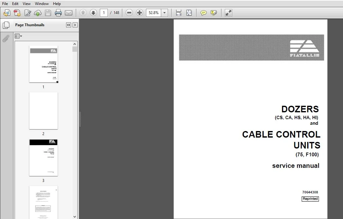
Fiat Allis CS,CA,HS,HA, HI Dozers & 75, F100 Cable Control Unit Service Manual
Part Number : (70644308)
Description
Fiat Allis CS,CA,HS,HA, HI Dozers & 75, F100 Cable Control Unit Service Manual (70644308)
FILE DETAILS:
Fiat Allis CS,CA,HS,HA, HI Dozers & 75, F100 Cable Control Unit Service Manual (70644308)
- Format: PDF
- Language: English
- Brand: Fiat
- Type of machine: Dozers
- Type of document: Service Manuals
- Model: Fiat Allis CS,CA,HS,HA, HI Dozers & 75, F100 Cable Control Units
- Number of Pages: 148 pages
- Print No.: 70644308
FIAT ALLIS CS,CA,HS,HA, HI DOZERS & 75, F100 CABLE CONTROL UNIT SERVICE MANUAL (70644308) – PDF DOWNLOAD:
SCREENSHOTS OF THE MANUAL:
DESCRIPTION:
Fiat Allis CS,CA,HS,HA, HI Dozers & 75, F100 Cable Control Unit Service Manual (70644308)
- Always furnish serial number if making an inquiry to dealer or factory about this machine. Many equipment owners employ the Dealer Service Department for all work other than routine lubrication and minor service. This practice is encouraged. as our Dealers are well informed and equipped to render efficient service by factory trained mechanics.
- This manual may not be reprinted or reproduced. either in whole or in part, without written permission of Fiatallis ®. Illustrations show standard and optional items.
- IMPORTANT The information in this manual was current at the time of publication. It is our policy to constantly improve our product and to ,make available additional items.
- These changes may affect procedures outlined in this manual. If variances are observed, verify the information through your Dealer.
- Study the Operation and Maintenance instruction Manual before starting. operating, maintaining. fueling. or servicing machine. Read and heed all machine-mounted safety signs beiore star. ting. operating. maintaining. iueling or servicing machine.
- Machine-mounted safety signs have been color coded yeil0w with black border and lettering for WARNING and red with white border and lettering for DANGER points. Never attempt to operate the machine or its tools from any position other than seated in the operator’s seat. Keep head. body. limbs. hands and feel inside operator‘s compartment at all times to reduce exposure to hazards outside the operator’s compartment.
- Do not allow unauthorized personnel to operate. service or maintain this machine. Always check work area for dangerous features. The following are examples of dangerous work areas: slopes, overhangs. timber. demolitions. tire. high walls, dropoll. backfllls. rough terrain. ditches. ridges. excavations. heavy tralfic. crowded parking. crowded maintenance and closed areas.
- Use extreme care when in areas such as these. An operator must know the machine’s capabilities. When working on slopes or near dropofls be alert to avoid loose or soil conditions that could cause sudden tipping or loss of con- trol. Do not jump on or off machine. Keep two hands and one foot. or two feet and one hand. In contact with steps. grab rails and handles at all times.
- Do not use controls or hoses as handhoids when climbing on or off machine. Hoses. and controls are movable and do not provide a solid support. Controls also may be inadvertently moved causing accidental machine or equipment movement. Keep operator’s compartment. stepping points. grab-rails and handles clear of foreign objects. oil, grease. mud or snow accumulation to minimize the danger of slipping or stumbling.
- Clean mud or grease from shoes before attempting to mount or operate the machine. Becareiui oi slippery conditions on stepping points. hand rails. and on the ground. Wear safety boots or shoes that have a high slip resistant sole material.
- For your personal protection. do not attempt to climb on or oil machine while machine is in motion. Never leave the machine unattended with the engine running. Always lock up machine when leaving it unattended: Return keys to authorized security. Heed all shutdown procedures of the Operation and Maintenance instruction Manual Ahvays set the parking brake when leaving the machine for any reason.
- Do not wear rings. wrist watches. Jewelry. loose or hanging apparel. such as ties. torn clothing. scarves. unbuitone-d, or unzipped jackets that can catch on moving parts. Wear proper safety equipment as authorized for the too. Examples: hard hats. safety shoes, heavy gloves, ear protectors. safety glasses or goggles. retlecior vests, or respirators. Consult your employer for specific safety equipment requirements.
TABLE OF CONTENTS:
Fiat Allis CS,CA,HS,HA, HI Dozers & 75, F100 Cable Control Unit Service Manual (70644308)
1 HYDRAULIC SYSTEM (Rotor to Topic 7A (or 6(115′) moldioard tilt information)
A. Intraimiinn……………………… 5
B.mmpnescuptMn……………………. 5
C. Contmivalve DescripiimandOpex-atim. . . . . . . . . . . . . . . 5
D. Hydmnlic’l‘anchscription……………….. 8
E. StanthrdCyIindermscriptimandOPemiion…….. ….. 9
P.‘I‘iltCyIindorDoscription………………… 10
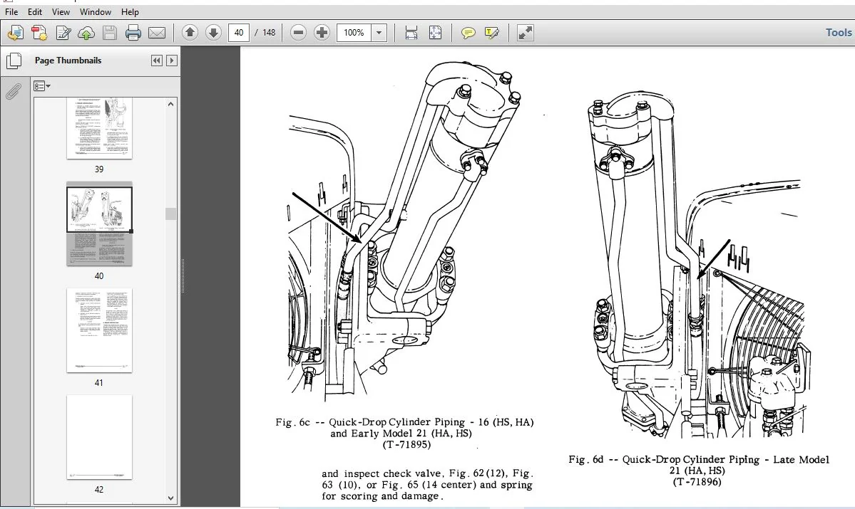
G. Quick-Droprlindex-DcscfiptionandOpoI-ation … .. . . … . 11
n.HydraulicSystemOilI-‘low………………… 12A
1. Hydraulic System Lubricant Specifications, Capacities, Service . . . . 12A
J. HydraulicSystcmPrcssuroChart…………….. 128
2 TROUBLE SHOOTING AND PRESSURE CHECKING HYDRAULIC SYSTEM
(Refer to Topic 7A {or 6 (HS) moidboard tilt iniormation)
A.TroubleShooting……………………. 13
B. PressuraChocking…………………… 14
C. PressurcChecIdnchemlu………………… 15
D. PressureCheckingPump…………………. 17
3 CABLEINPORMATION
A.Introchiction……………………… 19
B.McasurinzCabIc……………………. 19
C. SafeguamioLangchabchiio……………… 19
D. CableSpeciflcatims…………………… 20
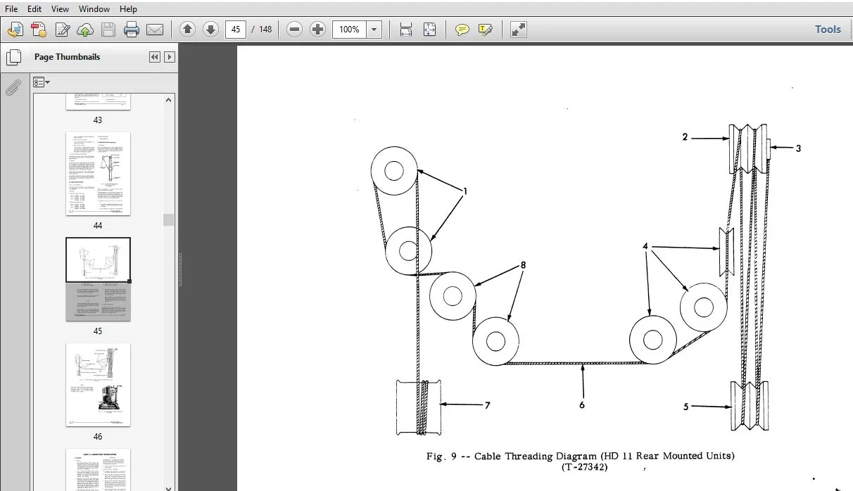
E.CabIcinmllationmovlng)………………… 20
4 INSPECTION INFORMATION
A. Bearings.. 23
B.SinitsandSpunes……………………. 23
C. 01199318………………………. 24
D.Gaskets……………………….. 24
E.Gears………………………… 24 ‘
5 F100 FRONT CABLE CONTROL UNIT
Lust-mum……………………… 25
B.Specifications……………………… 25
C.Adjustment:……………………… 28
D. ClinchandiioidinanJccBandsRepIaccmcnt ………… 27
E.Disassemhiy……………………… 2G
F.Cleaninxandlnspoction…………………. 31
G.Assemb1y………………………. 31
H. LubricantSpecifications, Capacity, andService . . . . . . . . . . . 33
5 75 REAR CABLE CONTROL UNIT
A.Doscription……………………… 35
B.Specifications……………………… 35
C.Adjustments……………………… 36
D. BrakeLAningRepiacement………………… 39
E.ClutchDiscchIaccmcnt………………… 39
I”.OilSealRephcemenl………………….. 40
G. CiutchShaitGeax-a, Bearings, Intermediate Gear, and Input
Pinimncplaocmcnt…………………… 43
II. Fairleads………………………. 49
I.installationinstmctions…………………. 50
J. [AbdumSpcciiicationmCamcity.andService . . . . . . . . . . . 51
7 NZER HYDRAULIC CONTROL UNITS (Refer to Topic 7A for 6 (HS)
moldboard tilt information)
A. Description (also see’TIYDRAULIC SYSTEM”) . . . . . . . . . . . . 53
B. HydnulicContrinoitRemos‘al ……………… 53
C. Hydraulic ConimlUniL Dimscmbiy andAssembinMA, HS) . . . . . 5-1
D. Hydraulic Control Unit Uppcr’Ihnchmoval, Diussombly and
Asmmbly11,16,21(HA,HS)………………. 55
E. HydmuflcContmlUnitInstaIIation …………….. 59
7A 6 (HS) MOLDBOARD TILT GROUP
A.Genera11)oscription………………….. 60
B. Specifications, Tonquos, Service, Fits and Tolerances . . . . . . . . 60
C. Description oiTiltGroanydrauilcSystem . . . . . . . . . . . . . 60
D. Troubleshooting…………………….. 608
‘ E.ControlValve……………………… 60C
F.Hydraulianmp…………………….. 60C
G. TiltCylinder……………………… 60D
8 HYDRAULIC CONTROL VALVES (Refer to Topic 7A for 6 (BS) moldooard
tiltinforrnatioo)
A. Description (Also see “HYDRAULIC SYSTEM’). . . . . . . . . . . . 61
B. ControiValreRsmoval-Singienotor. . . . . . . . . . . . . . . . 61
C. Control Valve Disassembly-Singie Rotor . . . . . . . . . . . . . . 61
D. ControlValreinspection-Singleltotor . . . . . . . . . . . . . . . 63
E. ControlValve Assembly-Single Rotor . . . . . . . . . . . . . . . 63
F. ControlValveInstallation—Snglefiotor ………….. 65
G. Triple Rotor Control Valve Disassembly and Assembly (PRIOR. APRIL 1967) 66C
CG. Triple Rotor Control Valve Dieassembly and Assembly (EFFECTIVE
APlegento.IIOOOOOOIOOOQIOOOOOOOOOO 66D
9 HYDRAULIC PUMPS (Refer to Topic 7A for 6 (RS) moldboard tilt information)
A. Description (Alecsee”lIYDRAUIJC SYSTEM”). . . . . . . . . . . . 67
Be Rem-……o…..o….-.oo……. 67
c. Install-3‘10″ 000IOQOQIOIDOOQOIOOOOOIOOOQ 67
D. 6(HA,HS)(HId-reco)……………oo-ao… 57
Es lleDtHydreco)………………..o.ooo 72
F.11,16,21(HA,HS)(Hydreco)………………. 74
G. 6,II(BA,RS)(’l‘ymne)…………………. 76A
10 HYDRAULIC CYLINDERS (Refer to Topic 7A for 6(Rs’) moldhoaui tilt information)
A. Standard, Quick-Drop, and Tilt Cylinder Identification (See ‘
“HYDRAULIC SYSTElif”foroperation) . . . . . . . . . . . . . . . 77
B. SianhrdCylinceremm’aIandinstallation . . . . . . . . . . . . . 78
C. RodPackingIUngReplacement………………. 79
D. Pistonl’ztcltingmngneplacement……………… 81
E. PistonRodWiperSealReplacement…………….. as
F. mick-Droprlindersll,16,210IA,RS)………….. 83
G. TiltCylindersll,16,21 (fiS)only…………… 85F
H. CylinderHeadandRodNutTox-ques . . . . . . . . . . . . . . . . . 98F
11 DOZER REMOVAL AND INSTALLATION
A. ModelCAandRADozerRemom……………… 89
B. ModelCAandllADozerInstaIlation…………….. 89
C. MochCSandlISDozerRemov-al……………… 90
D. ModchSandRSDozerInstaIIann…………….. 92
E. ModeIHIDozerRemoralandInstalIation . . . . . . . . . . . . . . 9213
12 FITS AND TOLERANCE (Refer to Topic 7A for 6013) moldhoard tilt information)
A. F-IOOanfCableControlUnit………………. 95
B.75RcarCableCmflmlUnit………………… 95
C. Control Valves (Refer to Topic 7A for 6 (HS) moldboard tilt information). 95
D. Pumps (RefertoTopie 7A for 6(HS) moldboerd tilt information) . . . . 95
E. Cylinder: (Referio’l‘opic 7A for 6(HS) moldboardtiitinformation) . . . 96
1′”. Dozen……………………….. 96
13 SERVICE’I‘OOLS……………………… 97
14 CONVERSIONTABLES……………………. 99
PLEASE NOTE:
- This is the SAME exact manual used by your dealers to fix your vehicle.
- The same can be yours in the next 2-3 mins as you will be directed to the download page immediately after paying for the manual.
- Any queries / doubts regarding your purchase, please feel free to contact [email protected]