Trusted Business
Verified & Licensed
Virus Free Files
100% Safe Downloads
Secure Payment
SSL Protected
Instant Delivery
Available Immediately
Fiat Hitachi Crawler Dozer D180 Workshop Manual – PDF DOWNLOAD
$28.95
Fiat Hitachi Crawler Dozer D180 Workshop Manual – PDF DOWNLOAD
Instant PDF Download
Available immediately
Save to Your Device
Download & keep forever
Antivirus Scanned
100% virus-free
Trusted Worldwide
175,000+ customers
Description
Fiat Hitachi Crawler Dozer D180 Workshop Manual – PDF DOWNLOAD
FILE DETAILS:
Fiat Hitachi Crawler Dozer D180 Workshop Manual – PDF DOWNLOAD
Language : English
Pages : 261
Downloadable : Yes
File Type : PDF
DESCRIPTION:
Fiat Hitachi Crawler Dozer D180 Workshop Manual – PDF DOWNLOAD
SAFETY RULES
– Check monitoring instruments at start-up and frequently during operations. in case the brake pressure gauge shows a pressure lower than the minimum operating pressure, stop immediately the machine .
– DO NOT CARRY RIDERS ON MACHINE
– Study and familiarise with escape routes alternate to normal exit routes. – Seat belts are required by current regulations to be provided with Roll Over Protection Structures or cabs. Keep safety belts fastened around you during operation.
– For your personal protection, do not climb on or off machine while machine is in motion.
– Make sure that exposed persons in the area of operation are clear of the machine, before starting the engine and operating the equipment. Sound horn. Obey all indications provided by flags and signals.
– NEVER COAST the machine down grades and slopes with the transmission in neutral or neutralised. Choose and shift into the most appropriate gear to keep the speed required, thus preventing any loss of control. – Do not operate machinery in a condition of extreme fatigue or illness. Be especially careful towards the end of working shift. – Do not operate machine with brakes out of adjustment.
– Operate the machine at speeds slow enough to ensure complete control at all times.
– Travel slowly over rough terrain, on slopes or near dropoffs, in congested areas or on ice or slippery surfaces.
– When backing, always look to where the machine is to be moved. Be alert to the position of exposed personnel. DO NOT OPERATE if exposed personnel enter the immediate work area. STOP THE MACHINE.
– Maintain a safe distance from other machines. Provide sufficient clearance for ground and visibility conditions. Yield right-of-way to loaded machines.
– Maintain clear vision of areas of travel or work. Keep cab windows clean and repaired. – When machines are operating in tandem, the pusher (rear) must be equipped with the appropriate deflectors to protect the unit in front from the air stream coming from the radiator.
– When pulling or towing through a cable or chain, do not start suddenly at full throttle; take-up slack carefully. Inspect carefully for flaws or troubles before using.
– Avoid kinking chains or cables. Do not pull through a kinked chain or cable to the high stresses and possibility
2.1 GENERAL DESCRIPTION
2.1.1 TRANSMISSION TORQUE CONVERTER HYDRAULIC DIAGRAM
- The transmission is of a “power-shift” type with three forward and three reverse speeds. The system is powered by a dual pump feeding the transmission and the torque converter
- (1). The pump sucks oil from the transmission housing through filter (6) and circulates it purifying further through filter (2). A valve (set at 2.5 bar) protects filter
- (2) against over pressures due to the clogging of the cartridge or excessively thick oil. The feeding pump of the hydraulic system steering clutches sucks the oil accumulated in the torque converter support housing, through a mesh filter (14) and returns it to the transmission housing. The oil delivered by feeding pump
- (1) after being purified by filter
- (2) reaches pressure relief valve
- (3) establishing and maintaining the pressure setting of the oil controlling the transmission clutches.
- Safety valve (16) protects the torque converter and the heat exchanger against accidental pressure increments, normally due to cold and excessively thick oil, discharging the flow excess into the pump delivery line
- (1). The oil flowing out the torque converter, passes through the heat exchanger, the manifold and it is distributed to the lube and cooling ducts of the transmission clutches. The maximum lube pressure is limited by valve
- (15) set at 3 bar. Modulating valves (9) make the engagement of the clutches progressive, regulating the pressure increment in the control circuits. A low engine lube oil pressure or an excessive lube oil temperature are indicated on the dashboard in the cab.
- Quick discharge valves on the 2nd and 3rd speed clutches, during the speed engagement phase, are in closed position, under the action of pressurised oil.
- When shifting from one speed to another, the relevant control cylinder is connected to the discharge and the pressure drop causes the centrifugal force to prevail over the action of the oil, moving the balls outwards, facilitating a quick discharge.
IMAGES PREVIEW OF THE MANUAL:
TABLE OF CONTENTS:
Fiat Hitachi Crawler Dozer D180 Workshop Manual – PDF DOWNLOAD
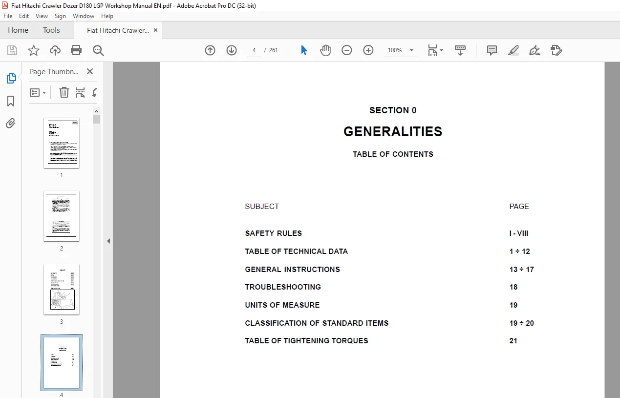
D180 CRAWLER DOZER........................................................  1
Workshop manual...........................................................  1
SUMMARY...................................................................  3
SECTION 0 GENERALITIES....................................................  4
	SAFETY RULES..........................................................  5
	TECHNICAL DATA TABLES................................................. 13
	GENERAL INSTRUCTIONS.................................................. 26
	TROUBLESHOOTING....................................................... 31
	UNITS OF MEASURE...................................................... 32
	CLASSIFICATION OF STANDARD COMPONENTS................................. 32
	TABLE OF TIGHTENING TORQUES........................................... 34
SECTION 1 ENGINE.......................................................... 35
	GENERAL SPECIFICATIONS................................................ 36
	SERIES "C" ENGINE DATA................................................ 38
	DIAGRAMS OF SERIES "C" ENGINE......................................... 41
	MOUNTING OF ENGINE ON FRAME........................................... 44
SECTION 2 TRANSMISSION.................................................... 45
	GENERAL DESCRIPTION................................................... 46
		TRANSMISSION TORQUE CONVERTER HYDRAULIC DIAGRAM...................  0
		Transmission housing..............................................  0
	TROUBLESHOOTING....................................................... 49
	TESTS................................................................. 53
		Torque converter stall test.......................................  0
		TRANSMISSION GEARSHIFTING ELECTRIC CONTROL VALVE..................  0
	PROCEDURES FOR THE REPAIR OF THE TORQUE CONVERTER..................... 68
		REMOVAL...........................................................  0
		RE-INSTALLATION...................................................  0
		DISASSEMBLY.......................................................  0
		REASSEMBLY........................................................  0
	PROCEDURES FOR THE REPAIR OF THE TRANSMISSION......................... 68
		REMOVAL...........................................................  0
		RE-INSTALLATION...................................................  0
		DISASSEMBLY.......................................................  0
		OVERHAUL OF THE FORWARD SPEED CLUTCH..............................  0
		OVERHAUL OF THE 3 rd SPEED........................................  0
		OVERHAUL OF THE REV SPEED CLUTCH..................................  0
		MODULATING VALVES (Disassembly / Assembly)........................  0
		PRESSURE RELIEF VALVE (Disassembly / Assembly)....................  0
	SPECIFICATIONS AND DATA............................................... 99
		GENERAL DATA......................................................  0
		TIGHTENING TORQUES (TORQUE CONVERTER).............................  0
		TRANSMISSION HOUSING..............................................  0
		TRANSMISSION DATA.................................................  0
		TRANSMISSION CLUTCH DISC..........................................  0
		LUBE OIL PRESSURE RELIEF VALVE....................................  0
		FORWARD REVERSE MODULATING VALVES.................................  0
		TRANSMISSION PRESSURE RELIEF VALVE AND TORQUE CONVERTER SAFETY....  0
		TORQUE CONVERTER / TRANSMISSION FEEDING PUMP......................  0
		OIL FILTERS.......................................................  0
SECTION 3 FINAL DRIVES....................................................110
	GENERAL DESCRIPTION...................................................111
		Final drive.......................................................112
	REPAIR PROCEDURES.....................................................114
		Disassembly.......................................................116
		Pulling the housing cover.........................................118
		Driven gear.......................................................119
		Driving gear shaft................................................119
		Description of installation of front seals (long life)............120
		Final drive (removal / disassembly)...............................114
		Final drive (assembly)............................................121
	SPECIFICATIONS AND DATA...............................................129
		Final drive shaft and bearing fittings............................129
		BEARING INSTALLATION SPECIFICATIONS AND DATA......................130
SECTION 4 BRAKES AND STEERING CLUTCHES....................................131
	GENERAL DESCRIPTION OF THE CIRCUIT....................................  0
		BRAKES AND STEERING CLUTCHES SYSTEM HYDRAULIC DIAGRAM.............  0
		MAIN COMPONENTS OF THE HYDRAULIC SYSTEM...........................  0
		REAR TRANSMISSION (transmission side section).....................  0
	TROUBLESHOOTING.......................................................  0
		DIAGNOSIS ON THE DISPLAY..........................................  0
	TESTS.................................................................  0
		PRESSURE TEST OF THE BRAKES AND STEERING CLUTCH CIRCUIT...........  0
		BRAKE PEDAL ADJUSTMENT............................................  0
		BRAKE SYSTEM PRESSURE TEST (with brake pedal).....................  0
		FEEDING VALVE TEST AND SETTING....................................  0
		CALIBRATION OF BRAKES/STEERING CLUTCH LEVERS......................  0
	REPAIR PROCEDURES Brake pedal valve...................................  0
		STEERING CLUTCH AND BRAKE.........................................  0
		BRAKES AND STEERING CLUTCHES......................................  0
		BEVEL GEAR UNIT...................................................  0
		BEVEL GEAR........................................................  0
		PROCEDURE FOR THE SETTING OF THE PINION BEARINGS PRE-LOAD.........  0
		PROCEDURE FOR THE SETTING OF THE BEVEL GEAR UNIT..................  0
	SPECIFICATIONS AND DATA...............................................  0
		BEVEL GEAR REDUCTION UNIT (General data / dimensions).............  0
		STEERING CLUTCHES.................................................  0
		BRAKE PEDAL VALVE.................................................  0
SECTION 5 UNDERCARRIAGE...................................................179
	GENERAL DESCRIPTION...................................................180
		GENERALITIES......................................................180
		MAIN COMPONENTS...................................................181
	TROUBLESHOOTING.......................................................184
	INSPECTIONS...........................................................185
		INSPECTION AND ADJUSTMENT OF TRACK CHAINS.........................185
		SETTING OF THE TRACK TENSIONER PRESSURE RELIEF VALVE..............186
	REPAIR PROCEDURES.....................................................187
		TRACK CHAIN (removal / installation)..............................187
		REPLACING A DAMAGED LINK AND RE-INSTALLATION......................189
		IDLER.............................................................191
		TRACK CHAIN SUPPORT ROLLERS (removal/installation/overhaul).......194
		TRACK CHAIN BOTTOM ROLLERS (removal / installation / overhaul)....196
	SPECIFICATIONS AND DATA...............................................200
		IDLER.............................................................200
	SPECIFICATIONS AND DATA...............................................201
		SPROCKETS.........................................................201
		TRACK CHAINS......................................................201
		BOTTOM ROLLERS....................................................202
		SUPPORT ROLLERS...................................................203
		TRACK TENSIONER DEVICE............................................204
		FRONT CROSS-MEMBER PIVOTS (*).....................................205
		FRONT CROSS-MEMBER PIVOTS.........................................205
		WEAR LIMITS.......................................................209
SECTION 6 DOZING EQUIPMENT HYDRAULIC SYSTEM...............................211
	GENERAL DESCRIPTION...................................................212
		OPERATION OF THE HYDRAULIC SYSTEM.................................212
		DIAGRAM OF DOZING EQUIPMENT HYDRAULIC SYSTEM......................215
		DOZER EQUIPMENT HYDRAULIC SYSTEM DIAGRAM..........................214
	TROUBLESHOOTING.......................................................216
	TESTS.................................................................220
		USE OF THE FLOW METER.............................................220
		FLOW TEST IN SINGLE CIRCUITS......................................220
		PUMP FLOW TEST....................................................221
	REPAIR PROCEDURES.....................................................223
		HYDRAULIC OIL RESERVOIR (Removal / installation)..................223
		Equipment hydraulic pump..........................................225
		Hydraulic control valve...........................................226
		Montage du godet..................................................227
	SPECIFICATIONS AND DAT................................................228
		Hydraulic control valve...........................................228
		Supply hydraulic pump.............................................229
		Blade lifting cylinder ball joint.................................230
		Blade lifting control cylinder....................................231
		Blade tilt control cylinder (Bulldozer version)...................232
		Blade tilt control cylinder (Angledozer version)..................233
		Ripper cylinder...................................................234
		Blade push arms and rods..........................................235
		Frame and rods....................................................236
		Ripper linkage....................................................237
SECTION 7 ELECTRICAL SYSTEM...............................................239
	SAFETY RULES..........................................................240
	ELECTRICAL SYSTEM.....................................................241
	FUSES.................................................................243
	LINK" FUSES AND COLD STARTING.........................................244
	MAIN SWITCH...........................................................245
	ENGINE STARTING SWITCH................................................245
	BACK-UP ALARM.........................................................246
	STARTER MOTOR.........................................................246
	INSTRUMENT PANEL / MONITOR............................................247
	MONITOR SENDERS.......................................................250
	BUZZER................................................................256
	RELAY - DIODES - DIVERTER BOX GROUP...................................257
	MAIN CONNECTORS 19 - 21 - 23 WAYS.....................................260
Questions? Email us: [email protected]
PLEASE NOTE:
- This is the SAME exact manual used by your dealers to fix your vehicle.
- The same can be yours in the next 2-3 mins as you will be directed to the download page immediately after paying for the manual.
- Any queries / doubts regarding your purchase, please feel free to contact [email protected]
S.M