Fiat Hitachi D180 Crawler Dozer Service Repair Manual – PDF DOWNLOAD
Original price was: $53.95.$18.95Current price is: $18.95.
Fiat Hitachi D180 Crawler Dozer Service Repair Manual
Description
Fiat Hitachi D180 Crawler Dozer Service Repair Manual
FILE DETAILS:
Fiat Hitachi D180 Crawler Dozer Service Repair Manual
Language : English
Pages : 259
Downloadable : YES
Format : PDF
Size : 8.88 MB
DESCRIPTION:
Fiat Hitachi D180 Crawler Dozer Service Repair Manual
SAFETY RULES:
Do not allow unauthorised personnel to operate service or maintain this machine. Do not wear rings, wrist watches, jewellery, loose or hanging apparels, such as ties, torn clothing, scarves, unbuttoned or unzipped jackets that can catch on moving parts. Wear proper safety equipment as recommended for the job. Examples: hard hat, heavy gloves, ear protection, safety glasses or goggles, reflector vests, respirator. Consult your employer for specific safety equipment requirements.
- Keep operator’s compartment, stepping points, grabrails and handles clear of foreign objects, oil, grease, mud or snow accumulation to minimise the danger of slipping or stumbling. Clean mud or grease from shoes before attempting to mount or operate the machine. Do not jump on or off the machine. Keep two hands and one foot, or two feet and one hand in contact with step grab rails and handles at all times. Do not use controls or hoses as hand holds when climbing on or off machine. Hoses and controls are movable and do not provide a solid support.
- Also, controls may be inadvertently moved causing accidental machine or equipment movement. Never attempt to operate the machine or its tools from any position other than seated in the operator’s seat. Keep head, body, limbs, hands and feet inside operator’s compartment at all times, to reduce exposure to hazards outside the operator’s compartment.
- Be careful of slippery conditions on stepping points, hand rails, and on the ground. Wear safety boots or shoes that have a high slip resistant sole material. Do not leave the machine until it is completely stopped. Check the seat safety belt at least twice a year. If there are signs of wear or fraying or other signs of weakness that could lead to failure, replace it.
STARTING:
NEVER START NOR OPERATE AN UNSAFE MACHINE. Before operating a machine, always ensure that any unsafe condition has been satisfactorily remedied. Check brakes, steering and attachment controls before moving. Advise the proper maintenance authority of any malfunctioning part or system. Be sure all protective guards or panels are in place, and all safety devices provided are in place and in good operating conditions. Be sure exposed personnel in the area of operation are clear of the machine before moving it or its attachments.
- WALK COMPLETELY AROUND the machine before mounting. Sound horn. Before starting machine, check, adjust and lock the operator’s seat for maximum comfort and control of the machine. Fasten your seat belt (when provided). Obey all flag signals and signs. Due to the presence on the machine of flammable fluids, never check or fill fuel reservoirs or batteries near open flames, smoking materials or sparks. REMEMBER THAT STARTING FLUID IS FLAMMABLE.
- Follow strictly the recommendations printed on containers and in the Operation and Maintenance Manual. DO NOT PUNCTURE OR BURN CONTAINERS. Containers must be stored in fresh, well ventilated places, out of reach of unauthorised persons. Follow strictly the instructions provided by the Manufacturer. Never use these products near open flames, smoking materials or sparks.
OPERATION :
Do not run the engine of this machine in closed areas without proper ventilation to remove deadly exhaust gases. Roll Over Protective Structures are required on loaders, dozers, graders, excavators. NEVER OPERATE machines without ROPS. Make sure the Operator’s compartment is free of foreign objects, especially if not firmly secured. Never use the machine to transport objects, unless proper securing points are provided.
TABLE OF CONTENTS:
Fiat Hitachi D180 Crawler Dozer Service Repair Manual
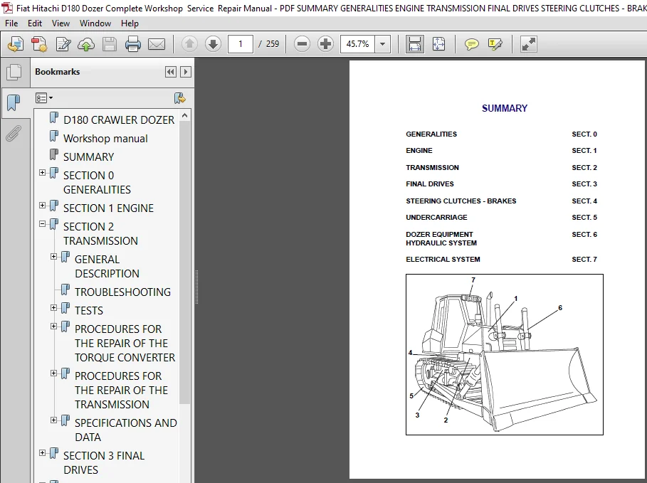
D180 CRAWLER DOZER........................................................  0
Workshop manual...........................................................  0
SUMMARY...................................................................  1
SECTION 0 GENERALITIES....................................................  2
	SAFETY RULES..........................................................  3
	TECHNICAL DATA TABLES................................................. 11
	GENERAL INSTRUCTIONS.................................................. 24
	TROUBLESHOOTING....................................................... 29
	UNITS OF MEASURE...................................................... 30
	CLASSIFICATION OF STANDARD COMPONENTS................................. 30
	TABLE OF TIGHTENING TORQUES........................................... 32
SECTION 1 ENGINE.......................................................... 33
	GENERAL SPECIFICATIONS................................................ 34
	SERIES "C" ENGINE DATA................................................ 36
	DIAGRAMS OF SERIES "C" ENGINE......................................... 39
	MOUNTING OF ENGINE ON FRAME........................................... 42
SECTION 2 TRANSMISSION.................................................... 43
	GENERAL DESCRIPTION................................................... 44
		TRANSMISSION TORQUE CONVERTER HYDRAULIC DIAGRAM...................  0
		Transmission housing..............................................  0
	TROUBLESHOOTING....................................................... 47
	TESTS................................................................. 51
		Torque converter stall test.......................................  0
		TRANSMISSION GEARSHIFTING ELECTRIC CONTROL VALVE..................  0
	PROCEDURES FOR THE REPAIR OF THE TORQUE CONVERTER..................... 66
		REMOVAL...........................................................  0
		RE-INSTALLATION...................................................  0
		DISASSEMBLY.......................................................  0
		REASSEMBLY........................................................  0
	PROCEDURES FOR THE REPAIR OF THE TRANSMISSION......................... 66
		REMOVAL...........................................................  0
		RE-INSTALLATION...................................................  0
		DISASSEMBLY.......................................................  0
		OVERHAUL OF THE FORWARD SPEED CLUTCH..............................  0
		OVERHAUL OF THE 3 rd SPEED........................................  0
		OVERHAUL OF THE REV SPEED CLUTCH..................................  0
		MODULATING VALVES (Disassembly / Assembly)........................  0
		PRESSURE RELIEF VALVE (Disassembly / Assembly)....................  0
	SPECIFICATIONS AND DATA............................................... 97
		GENERAL DATA......................................................  0
		TIGHTENING TORQUES (TORQUE CONVERTER).............................  0
		TRANSMISSION HOUSING..............................................  0
		TRANSMISSION DATA.................................................  0
		TRANSMISSION CLUTCH DISC..........................................  0
		LUBE OIL PRESSURE RELIEF VALVE....................................  0
		FORWARD REVERSE MODULATING VALVES.................................  0
		TRANSMISSION PRESSURE RELIEF VALVE AND TORQUE CONVERTER SAFETY....  0
		TORQUE CONVERTER / TRANSMISSION FEEDING PUMP......................  0
		OIL FILTERS.......................................................  0
SECTION 3 FINAL DRIVES....................................................108
	GENERAL DESCRIPTION...................................................109
		Final drive.......................................................110
	REPAIR PROCEDURES.....................................................112
		Disassembly.......................................................114
		Pulling the housing cover.........................................116
		Driven gear.......................................................117
		Driving gear shaft................................................117
		Description of installation of front seals (long life)............118
		Final drive (removal / disassembly)...............................112
		Final drive (assembly)............................................119
	SPECIFICATIONS AND DATA...............................................127
		Final drive shaft and bearing fittings............................127
		BEARING INSTALLATION SPECIFICATIONS AND DATA......................128
SECTION 4 BRAKES AND STEERING CLUTCHES....................................129
	GENERAL DESCRIPTION OF THE CIRCUIT....................................  0
		BRAKES AND STEERING CLUTCHES SYSTEM HYDRAULIC DIAGRAM.............  0
		MAIN COMPONENTS OF THE HYDRAULIC SYSTEM...........................  0
		REAR TRANSMISSION (transmission side section).....................  0
	TROUBLESHOOTING.......................................................  0
		DIAGNOSIS ON THE DISPLAY..........................................  0
	TESTS.................................................................  0
		PRESSURE TEST OF THE BRAKES AND STEERING CLUTCH CIRCUIT...........  0
		BRAKE PEDAL ADJUSTMENT............................................  0
		BRAKE SYSTEM PRESSURE TEST (with brake pedal).....................  0
		FEEDING VALVE TEST AND SETTING....................................  0
		CALIBRATION OF BRAKES/STEERING CLUTCH LEVERS......................  0
	REPAIR PROCEDURES Brake pedal valve...................................  0
		STEERING CLUTCH AND BRAKE.........................................  0
		BRAKES AND STEERING CLUTCHES......................................  0
		BEVEL GEAR UNIT...................................................  0
		BEVEL GEAR........................................................  0
		PROCEDURE FOR THE SETTING OF THE PINION BEARINGS PRE-LOAD.........  0
		PROCEDURE FOR THE SETTING OF THE BEVEL GEAR UNIT..................  0
	SPECIFICATIONS AND DATA...............................................  0
		BEVEL GEAR REDUCTION UNIT (General data / dimensions).............  0
		STEERING CLUTCHES.................................................  0
		BRAKE PEDAL VALVE.................................................  0
SECTION 5 UNDERCARRIAGE...................................................177
	GENERAL DESCRIPTION...................................................178
		GENERALITIES......................................................178
		MAIN COMPONENTS...................................................179
	TROUBLESHOOTING.......................................................182
	INSPECTIONS...........................................................183
		INSPECTION AND ADJUSTMENT OF TRACK CHAINS.........................183
		SETTING OF THE TRACK TENSIONER PRESSURE RELIEF VALVE..............184
	REPAIR PROCEDURES.....................................................185
		TRACK CHAIN (removal / installation)..............................185
		REPLACING A DAMAGED LINK AND RE-INSTALLATION......................187
		IDLER.............................................................189
		TRACK CHAIN SUPPORT ROLLERS (removal/installation/overhaul).......192
		TRACK CHAIN BOTTOM ROLLERS (removal / installation / overhaul)....194
	SPECIFICATIONS AND DATA...............................................198
		IDLER.............................................................198
	SPECIFICATIONS AND DATA...............................................199
		SPROCKETS.........................................................199
		TRACK CHAINS......................................................199
		BOTTOM ROLLERS....................................................200
		SUPPORT ROLLERS...................................................201
		TRACK TENSIONER DEVICE............................................202
		FRONT CROSS-MEMBER PIVOTS (*).....................................203
		FRONT CROSS-MEMBER PIVOTS.........................................203
		WEAR LIMITS.......................................................207
SECTION 6 DOZING EQUIPMENT HYDRAULIC SYSTEM...............................209
	GENERAL DESCRIPTION...................................................210
		OPERATION OF THE HYDRAULIC SYSTEM.................................210
		DIAGRAM OF DOZING EQUIPMENT HYDRAULIC SYSTEM......................213
		DOZER EQUIPMENT HYDRAULIC SYSTEM DIAGRAM..........................212
	TROUBLESHOOTING.......................................................214
	TESTS.................................................................218
		USE OF THE FLOW METER.............................................218
		FLOW TEST IN SINGLE CIRCUITS......................................218
		PUMP FLOW TEST....................................................219
	REPAIR PROCEDURES.....................................................221
		HYDRAULIC OIL RESERVOIR (Removal / installation)..................221
		Equipment hydraulic pump..........................................223
		Hydraulic control valve...........................................224
		Montage du godet..................................................225
	SPECIFICATIONS AND DAT................................................226
		Hydraulic control valve...........................................226
		Supply hydraulic pump.............................................227
		Blade lifting cylinder ball joint.................................228
		Blade lifting control cylinder....................................229
		Blade tilt control cylinder (Bulldozer version)...................230
		Blade tilt control cylinder (Angledozer version)..................231
		Ripper cylinder...................................................232
		Blade push arms and rods..........................................233
		Frame and rods....................................................234
		Ripper linkage....................................................235
SECTION 7 ELECTRICAL SYSTEM...............................................237
	SAFETY RULES..........................................................238
	ELECTRICAL SYSTEM.....................................................239
	FUSES.................................................................241
	LINK" FUSES AND COLD STARTING.........................................242
	MAIN SWITCH...........................................................243
	ENGINE STARTING SWITCH................................................243
	BACK-UP ALARM.........................................................244
	STARTER MOTOR.........................................................244
	INSTRUMENT PANEL / MONITOR............................................245
	MONITOR SENDERS.......................................................248
	BUZZER................................................................254
	RELAY - DIODES - DIVERTER BOX GROUP...................................255
	MAIN CONNECTORS 19 - 21 - 23 WAYS.....................................258
FIAT HITACHI D180 CRAWLER DOZER SERVICE REPAIR MANUAL – PDF DOWNLOAD:
IMAGES PREVIEW OF THE MANUAL:
PLEASE NOTE:
- This is the SAME MANUAL used by the dealerships to diagnose your vehicle
- No waiting for couriers / posts as this is a PDF manual and you can download it within 2 minutes time once you make the payment.
- Your payment is all safe and the delivery of the manual is INSTANT – You will be taken to the DOWNLOAD PAGE.
- So have no hesitations whatsoever and write to us about any queries you may have : heydownloadss @gmail.com