Trusted Business
Verified & Licensed
Virus Free Files
100% Safe Downloads
Secure Payment
SSL Protected
Instant Delivery
Available Immediately
Fiat Hitachi Excavator EX355 Operational Principle Technical Manual – PDF DOWNLOAD
$26.95
Fiat Hitachi Excavator EX355 Operational Principle Technical Manual – PDF DOWNLOAD
Instant PDF Download
Available immediately
Save to Your Device
Download & keep forever
Antivirus Scanned
100% virus-free
Trusted Worldwide
175,000+ customers
Description
Fiat Hitachi Excavator EX355 Operational Principle Technical Manual – PDF DOWNLOAD
FILE DETAILS:
Fiat Hitachi Excavator EX355 Operational Principle Technical Manual – PDF DOWNLOAD
Language : English
Pages : 142
Downloadable : Yes
File Type : PDF
DESCRIPTION:
Fiat Hitachi Excavator EX355 Operational Principle Technical Manual – PDF DOWNLOAD
TO THE READER
• This manual is written for an experienced technician to provide technical information needed to maintain and repair this machine.
– Be sure to thoroughly read this manual for correct information concerning the service procedures.
– If you have any questions or comments, or if you found any errors regarding the contents of this manual, please contact
FOLLOW SAFETY PRECAUTIONS
• Carefully read and observe all safety signs on the machine and read all safety precautions in this Manual.
• Safety signs should be installed, maintained, and replaced when necessary
If a safety sign or this Manual are damaged or missing, obtain a replacement from your FIATHITACHI Dealer in the same way you order a spare part (be sure to detail machine model and serial number upon ordering).
Learn how to operate the machine and its controls correctly and safely. • Allow only trained, qualified, authorised personnel to operate the machine.
• Keep the machine in proper working conditions. – Unauthorised changes to the machine may impair function and/or safety and affect machine life.
• Safety messages in this Chapter “SAFETY PRECAUTIONS”, are intended to illustrate basic safety procedures of the machine. However, it is impossible for these safety messages to cover every hazardous situation you may encounter.
If you have any doubts, consult your direct supervisor prior to operating or servicing the machine
IMAGES PREVIEW OF THE MANUAL:
TABLE OF CONTENTS:
Fiat Hitachi Excavator EX355 Operational Principle Technical Manual – PDF DOWNLOAD
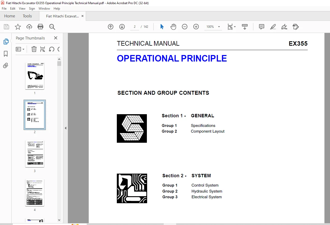
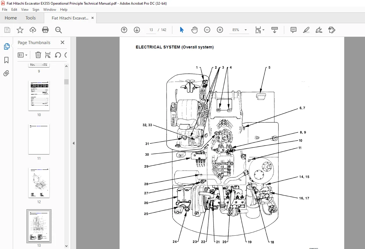
TECHNICAL MANUAL
 OPERATIONAL PRINCIPLE................................  1
OPERATIONAL PRINCIPLE..................................................  2
GENERAL................................................................  5
	Group 1 - Specifications...........................................  6
		EXCAVATOR DIMENSIONS...........................................  6
		EXCAVATOR DIMENSIONS...........................................  7
		EXCAVATOR PERFORMANCE..........................................  8
		ENGINE.........................................................  8
		ENGINE ACCESSORY...............................................  9
		HYDRAULIC DEVICES..............................................  9
		ELECTRICAL EQUIPMENT........................................... 10
	Group 2 - Component layout......................................... 12
		MAIN COMPONENTS................................................ 12
		ELECTRICAL SYSTEM.............................................. 13
		ELECTRICAL SYSTEM.............................................. 14
		ELECTRICAL SYSTEM.............................................. 15
		ELECTRICAL SYSTEM.............................................. 16
		OTHER COMPONENTS............................................... 17
SYSTEM................................................................. 20
	Group 1 - Control system........................................... 21
		OUTLINE........................................................ 21
		ENGINE CONTROL................................................. 22
		PUMP CONTROL................................................... 28
		VALVE CONTROL.................................................. 29
		OTHER CONTROL FUNCTIONS........................................ 33
	Group 2 - Hydraulic system......................................... 35
		MAIN CIRCUIT................................................... 35
		PILOT CIRCUIT.................................................. 36
		NEUTRAL CIRCUIT................................................ 38
		SINGLE ACTUATOR OPERATION...................................... 38
		COMBINED OPERATION............................................. 40
	Group 3 - Electrical system........................................ 45
		OUTLINE........................................................ 45
		ELECTRIC POWER CIRCUIT......................................... 46
		BULB CHECK CIRCUIT............................................. 47
		ACCESSORY CIRCUIT.............................................. 48
		PREHEAT CIRCUIT................................................ 50
		STARTING CIRCUIT............................................... 52
		CHARGING CIRCUIT............................................... 54
		SURGE VOLTAGE PREVENTION CIRCUIT............................... 57
		ENGINE STOP CIRCUIT............................................ 58
COMPONENT OPERATION.................................................... 60
	Group 1 - Pump device.............................................. 61
		OUTLINE........................................................ 61
		MAIN PUMP...................................................... 62
		REGULATOR...................................................... 64
		PILOT PUMP..................................................... 71
		N SENSOR....................................................... 71
		PUMP DELIVERY PRESSURE SENSOR.................................. 71
	Group 2 - Swing device............................................. 73
		OUTLINE........................................................ 73
		SWING MOTOR.................................................... 74
		SWING PARKING BRAKE............................................ 76
		VALVE UNIT..................................................... 77
		SWING REDUCTION GEAR........................................... 79
	Group 3 - Control valve............................................ 81
		OUTLINE........................................................ 81
		HYDRAULIC CIRCUIT.............................................. 86
		FLOW COMBINER VALVE............................................ 90
		PUMP CONTROL VALVE............................................. 92
		MAIN RELIEF VALVE.............................................. 94
		OVERLOAD RELIEF VALVE.......................................... 95
		ARM REGENERATIVE VALVE......................................... 96
		BOOM REGENERATIVE VALVE........................................ 98
		ARM ANTI-DRIFT VALVE...........................................100
		ARM ANTI-DRIFT VALVE (On Rod Side) /
 BOOM ANTI-DRIFT VALVE....103
		BUCKET FLOW RATE CONTROL VALVE.................................104
		TRAVEL FLOW RATE CONTROL VALVE.................................106
		BYPASS SHUT-OUT VALVE..........................................108
		NEEDLE VALVE...................................................110
	Group 4 - Pilot valve..............................................111
		OUTLINE........................................................111
		OPERATION......................................................113
	Group 5 - Travel device............................................121
		OUTLINE........................................................121
		TRAVEL MOTOR...................................................122
		PARKING BRAKE..................................................124
		TRAVEL SPEED CONTROL...........................................126
		TRAVEL BRAKE VALVE.............................................128
		TRAVEL REDUCTION GEAR..........................................130
	Group 6 - Other components (Upperstructure)........................133
		PILOT SHUT-OFF VALVE...........................................133
		SHOCKLESS VALVE................................................134
		SOLENOID VALVE UNIT............................................136
		PILOT RELIEF VALVE.............................................138
		EC MOTOR.......................................................138
	Group 7 - Other components (Undercarriage).........................139
		SWING BEARING..................................................139
		CENTER JOINT...................................................140
		TRACK ADJUSTER.................................................141
Customer Support: [email protected]
PLEASE NOTE:
- This is the SAME MANUAL used by the dealerships to diagnose your vehicle
- No waiting for couriers / posts as this is a PDF manual and you can download it within 2 minutes time once you make the payment.
- Your payment is all safe and the delivery of the manual is INSTANT – You will be taken to the DOWNLOAD PAGE.
- So have no hesitations whatsoever and write to us about any queries you may have : heydownloadss @gmail.com
S.M