Trusted Business
Verified & Licensed
Virus Free Files
100% Safe Downloads
Secure Payment
SSL Protected
Instant Delivery
Available Immediately
Fiat Hitachi WHEEL LOADER W110-W130 130PL Service Manual – PDF DOWNLOAD
$27.95
Fiat Hitachi WHEEL LOADER W110-W130 130PL Service Manual – PDF DOWNLOAD
Instant PDF Download
Available immediately
Save to Your Device
Download & keep forever
Antivirus Scanned
100% virus-free
Trusted Worldwide
175,000+ customers
Description
Fiat Hitachi WHEEL LOADER W110-W130 130PL Service Manual – PDF DOWNLOAD
FILE DETAILS:
Fiat Hitachi WHEEL LOADER W110-W130 130PL Service Manual – PDF DOWNLOAD
Language : English
Pages : 393
Downloadable : Yes
File Type : PDF
DESCRIPTION:
Fiat Hitachi WHEEL LOADER W110-W130 130PL Service Manual – PDF DOWNLOAD
SAFETY RULES
GENERALITIES
- Read this Manual carefully before starting, operating, maintaining, fuelling or servicing the machine. Read and comply with all safety precautions before any intervention.
- Do not allow unauthorised personnel to operate or service this machine. Do not wear rings, wrist watches, jewellery, loose or hanging garments, such as ties, torn clothing, scarves, unbuttoned or unzipped jackets that can get caught in moving parts. Wear certified safety clothes such as: hard hat, no-slip footwear, heavy gloves, ear protection, safety glasses, reflector vests, respirators.
- Ask your employer about specific safety equipment requirements. Keep the operator’s compartment, step plates, grab-rails and handles clean and clear of foreign objects, oil, grease, mud or snow to minimize the danger of slipping or stumbling. Remove mud or grease from your shoes before attempting to mount or operate the machine. Do not jump on or off the machine. Always keep both hands and one foot, or both feet and one hand in contact with steps and grab rails.
- Do not use controls or hoses as hand holds when climbing on or off the machine. Hoses and controls are movable parts and do not provide solid support. Besides, controls may be inadvertently moved and cause unexpected movement of the machine or its attachments.
- Never operate the machine or its attachments from any position other than sitting in the driver’s seat. Keep head, body, limbs, hands and feet inside the operator’s compartment at all times to reduce exposure to external hazards . Be careful of possible slippery conditions of the steps and hand rails as well as of the ground around the machine. Do not leave the machine until it is has come to a complete stop. Check the seat safety belt at least twice per year and replace it if it shows signs of wear, fraying or other weakness that could lead to failure. STARTING NEVER START OR OPERATE A FAILED MACHINE.
- Before operating the machine, always ensure that any unsafe condition has been satisfactorily corrected. Check brakes, steering and attachment controls before moving off. Report any malfuctioning part or system to the maintenance managers for proper action. Ensure all protective guards and panels as well as all safety devices provided are in place and in good operating condition.
- Ensure that nobody is in the machine operating range before moving off or operating the attachment. WALK COMPLETELY AROUND the machine before mounting. Sound the horn. Before starting machine, check, adjust and lock the driver’s seat for maximum comfort and control of the machine. Fasten your seat belts(when fitted). Obey all flag signals and signs. Due to the presence of flammable fluids on the machine, never check or fill fuel tanks or accumulator batteries near fires, open flames, or sparks.
- REMEMBER THAT SPECIAL STARTING FLUIDS ARE FLAMMABLE. Scrupolously follow recommendations printed on the containers and in this Manual. DO NOT PUNCTURE OR BURN CONTAINERS. Containers must be stored in fresh, well ventilated places and out of the reach of unauthorised persons. Strictly follow the instructions provided by the Manufacturer. Never use these products near fires, open flames, or sparks
IMAGES PREVIEW OF THE MANUAL:
TABLE OF CONTENTS:
Fiat Hitachi WHEEL LOADER W110-W130 130PL Service Manual – PDF DOWNLOAD
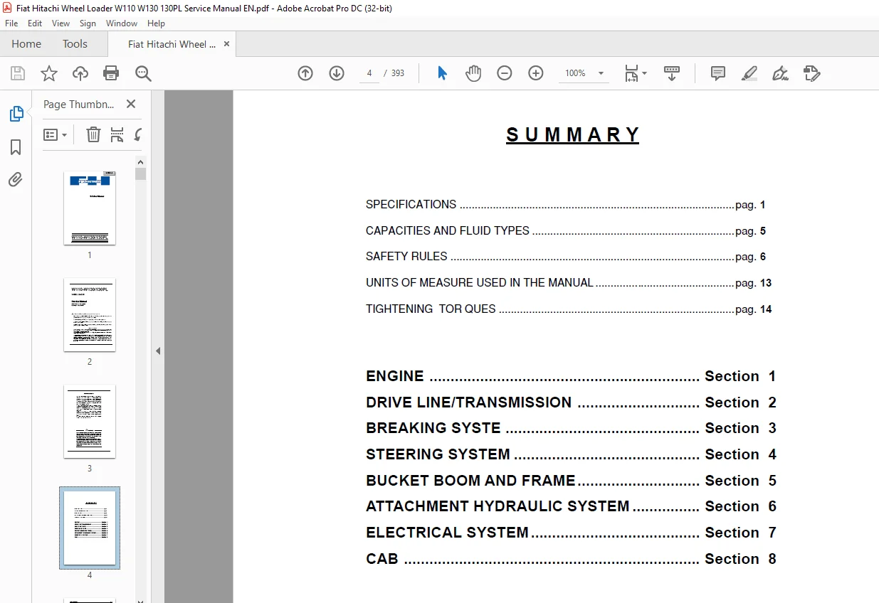
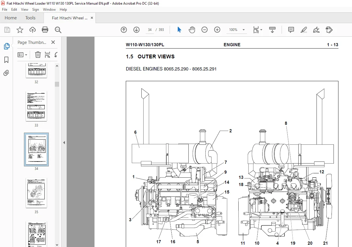
Service Manual....................................................................  1
S U M M A R Y.....................................................................  4
	SPECIFICATIONS - WHEEL LOADER W110............................................  5
	FLUIDS AND CAPACITY TABLE..................................................... 10
	SAFETY RULES.................................................................. 17
	UNITS OF MEASURE.............................................................. 18
	TORQUE TABLES.................................................................  0
ENGINE............................................................................ 21
	1.1 GENERAL DESCRIPTION....................................................... 22
	1.2 GENERAL SPECIFICATIONS.................................................... 23
	1.3 DATA - MOUNTING CLEARANCES................................................ 26
	1.4 INJECTION PUMP SETTING DATA............................................... 32
		1.4.1 ENGINE 8065.25.290 (W110)........................................... 32
		1.4.2 ENGINE 8065.25.291 (W130/130PL)..................................... 33
	1.5 OUTER VIEWS............................................................... 34
	1.6 ENGINE SUPPORTS........................................................... 35
	1.7 MAIN TIGHTENING TORQUES AND PRESSURE PICK-UP POINTS....................... 36
	1.8 LUBRICATION SYSTEM........................................................ 37
	1.9 COOLING SYSTEM............................................................ 38
		1.9.1 GENERAL DESCRIPTION................................................. 39
		1.9.2 RADIATOR............................................................ 40
	1.10 FUEL SYSTEM.............................................................. 41
		1.10.1 FUEL RESERVOIR..................................................... 42
	1.11 AIR INTAKE AND EXHAUST SYSTEM............................................ 43
		1.11.1 GENERAL DESCRIPTION................................................ 43
		1.11.2 TURBOCHARGER....................................................... 43
		1.11.3 AIR CLEANER........................................................ 45
	1.12 ELECTRICAL SYSTEM........................................................ 46
		1.12.1BATTERIES........................................................... 46
		1.12.2 STARTER SWITCH..................................................... 46
		1.12.3 STARTING A COLD ENGINE............................................. 47
		1.12.4 ENGINE CUT-OFF DEVICE.............................................. 47
		1.12.5 ENGINE PRE-HEATING SEQUENCE........................................ 48
		1.12.6 PRE-HEATING MALFUNCTION WARNING LAMP MODES......................... 48
		1.12.7 ACCELERATOR CONTROL LINKAGE........................................ 49
TRANSMISSION...................................................................... 50
	2.1 GENERAL DESCRIPTION....................................................... 51
	2.2 TORQUE CONVERTER - TRANSMISSION........................................... 52
	2.3 TORQUE CONVERTER.......................................................... 62
	2.4 TRANSMISSION - TORQUE CONVERTER PUMP...................................... 65
	2.5 TRANSMISSION.............................................................. 66
		2.5.1 DIRECTION CLUTCHES SHAFT............................................ 66
		2.5.2 POWER TRAIN DIAGRAM W110 - W130..................................... 71
		2.5.3 TRANSMISSION CONTROL VALVE.......................................... 73
		2.5.4 TRANSMISSION CONTROL SYSTEM......................................... 89
		2.5.5 CONFIGURATION OF AUTOMATIC TRANSMISSION (Var. W110 - W130/130PL).... 94
	2.6. DISASSEMBLY/REASSEMBLY TRANSMISSION...................................... 96
		2.6.1 DISASSEMBLY......................................................... 96
		2.6.2 REASSEMBLY..........................................................123
		2.6.3. Troubleshooting guide..............................................158
		2.6.4 Standard values for maintenance.....................................161
		2.6.5 Tightening torque values for main bolts.............................163
	2.7 OIL CIRCUIT...............................................................165
	2.8 PROP SHAFTS...............................................................167
	2.9 FRONT AND REAR AXLES......................................................169
		2.9.1 AXLE................................................................169
		2.9.2 DIFFERENTIAL........................................................173
		2.9.3 FINAL DRIVES........................................................175
		2.9.4 AXLES...............................................................177
	2.10 WHEELS...................................................................208
		2.10.1TYRES...............................................................208
BRAKING SYSTEM....................................................................210
	3.1 GENERAL DESCRIPTION.......................................................211
	3.2 OPERATION.................................................................213
		3.2.1 OPERATING CONDITIONS................................................213
	3.3 DISC BRAKE................................................................216
	3.4 BRAKE PEDAL VALVE.........................................................217
		3.4.1 CIRCUIT SEPARATION VALVE OPERATION INSIDE THE BRAKING SYSTEM........219
	3.5 PARKING BRAKE CONTROL VALVE...............................................220
	3.6 PARKING BRAKE.............................................................221
		3.6.1 MANUAL RELEASE PROCEDURE............................................221
		3.6.2 DISC PARKING BRAKE OPERATION........................................222
		3.6.3 BRAKE DISENGAGEMENT.................................................222
	3.7 OTHER COMPONENTS..........................................................223
		3.7.1 BRAKE ACCUMULATOR...................................................223
		3.7.2 CHECK VALVE.........................................................223
	3.8 BRAKE PEDAL VALVE HYDRAULIC CONNECTIONS...................................224
	3.9 DIAGNOSTICS AND TESTING...................................................225
		3.9.1 BRAKE CONTROL PRESSURE TESTING TEST.................................227
		3.9.2 MINIMUM AND MAXIMUM ACCUMULATOR RECHARGE PRESSURE ADJUSTMENT........228
		3.9.3 PARKING BRAKE ENGAGEMENT TEST.......................................229
		3.9.4 ACCUMULATOR PRE-CHARGE TEST.........................................230
		3.9.5 ACCUMULATOR PRE-CHARGE RESET INSTRUCTIONS...........................231
		3.9.6 BLEEDING THE BRAKE SYSTEM...........................................232
		3.9.7 BRAKE DISC WEAR CHECK...............................................233
STEERING SYSTEM...................................................................234
	4.1 GENERAL DESCRIPTION.......................................................235
	4.2 PRINCIPLES OF OPERATION OF MAIN PRIORITY VALVE............................239
	4.3 STEERING VALVE (ORBITROL).................................................240
		4.3.1 Removal.............................................................241
		4.3.2 MAIN PRIORITY VALVE.................................................246
		4.3.3 SECONDARY PRIORITY VALVE (OP- TIONAL)...............................247
		4.3.4 CUSHION VALVE.......................................................248
		4.3.5 STEERING CYLINDERS..................................................249
		4.3.6 MULTIPLE CHECK VALVE................................................251
BUCKET BOOMS AND FRAME............................................................252
	5.1 LOAD HANDLING SYSTEM......................................................253
	5.2 BOOM, BELLCRANK AND BUCKET................................................254
		5.2.1 GENERAL DESCRIPTION.................................................254
		5.2.2 BUCKET..............................................................256
		5.2.3 BUCKET LEVELER......................................................257
		5.2.4 BOOM KICKOUT (optional).............................................258
	5.3 FRAME PIVOT PINS..........................................................259
	5.4 BUCKET STOPS..............................................................260
EQUIPMENT HYDRAULIC SYSTEM........................................................261
	6.1 GENERAL DESCRIPTION.......................................................262
	6.2 OIL CIRCUIT...............................................................263
		6.2.1 EQUIPMENT HYDRAULIC CIRCUIT.........................................263
	6.3 HYDRAULIC SYSTEM PUMP.....................................................266
		6.3.1 INSPECTION AND REPAIR OF EQUIPMENT -STEERING PUMP...................269
	6.4 EQUIPMENT CONTROL VALVE...................................................271
		6.4.1 GENERAL DESCRIPTION.................................................271
		6.4.2 OPERATION OF CONTROL VALVE..........................................279
		6.4.3 PRESSURE RELIEF VALVE...............................................284
	6.5 CONTROL VALVE CONTROLS....................................................287
		6.5.1 HYDRAULIC CONTROL VALVE CONTROL (Variant)...........................288
	6.6 HYDRAULIC OIL RESERVOIR...................................................292
	6.7 CYLINDERS.................................................................293
		6.7.1 BOOMS CYLINDERS.....................................................293
		6.7.2 BUCKET TILT CYLINDER................................................293
	6.8 L.T.S. ANTI-PITCHING SYSTEM (Variant).....................................296
		6.8.1 DESCRIPTION.........................................................296
		6.8.2 DISCHARGE OF THE ACCUMULATORS.......................................296
		6.8.3 L.T.S. HYDRAULIC DIAGRAM............................................298
		6.8.4 FUNCTIONAL TESTS OF L.S.T. SYSTEM...................................299
		6.8.5 TEST OF ACCUMULATOR PRECHARGE.......................................300
		6.8.6 INSTRUCTIONS FOR THE RESETTING OF ACCUMULATOR PRECHARGE.............301
	6.9 SUPPLEMENTARY HYDRAULIC FUNCTION (Variant)................................302
ELECTRICAL SYSTEM.................................................................303
	SAFETY RULES..................................................................304
	7.1 GENERAL LAY-OUT OF ELECTRICAL SYSTEM......................................305
	7.2 LOGIC BOARD AND CAB CONNECTIONS...........................................306
		7.2.1 CONNECTIONS - RELAYS - TIMERS - BUZZER..............................306
		7.2.2 FUSES...............................................................307
	7.3 CONNECTORS................................................................308
	7.4 METERS AND SWITCHES CLUSTER...............................................310
		7.4.1 INDICATORS ON INSTRUMENT PANEL......................................312
	7.5 SWITCH PANEL..............................................................312
	7.6 GEARSHIFT SELECTOR........................................................313
	7.7 STARTER SWITCH............................................................314
	MACHINE GROUPS ELECTRIC DIAGRAMS..............................................332
CAB...............................................................................365
	8.1 GENERAL DESCRIPTION.......................................................366
	8.2 WINDSCREEN WIPERS AND WASHERS.............................................367
	8.3 HEATER....................................................................368
		8.3.1 GENERALITIES........................................................368
		8.3.2 MAIN COMPONENTS AND SPECIFICATIONS..................................368
	8.4 GLASSES...................................................................369
		8.4.1 CHARACTERISTICS.....................................................369
		8.4.2 DISASSEMBLY AND ASSEMBLY............................................370
	8.5 REPAIR....................................................................373
		8.5.1 CAB (REMOVAL/INSTALLATION)..........................................373
	8.6 AIR CONDITIONING UNIT.....................................................376
		8.6.1 OPERATING INSTRUCTIONS..............................................376
		8.6.2 TECHNICAL DATA......................................................377
		8.6.3 SERVICE PRECAUTIONS.................................................378
		8.6.4 TOOL CONNECTIONS....................................................380
		8.6.5 DISCHARGING.........................................................381
		8.6.6 REFRIGERANT CHARGING................................................381
		8.6.7 LEAK INSPECTION.....................................................382
	8.7 TROUBLESHOOTING...........................................................384
Need help? Contact: [email protected]
PLEASE NOTE:
- This is the SAME exact manual used by your dealers to fix your vehicle.
- The same can be yours in the next 2-3 mins as you will be directed to the download page immediately after paying for the manual.
- Any queries / doubts regarding your purchase, please feel free to contact [email protected]
S.M