Flight Medical Flight 60 Ventilator Service Manual – PDF
Original price was: $65.00.$15.95Current price is: $15.95.
Complete factory service manual for Flight Medical Flight 60 and F60 Dual Limb Ventilators. Professional technical documentation covering installation, calibration, troubleshooting, and repair procedures for these portable mechanical ventilation systems. Includes detailed module replacement procedures, pneumatic/electrical diagrams, software management, Operation Verification Procedure (OVP), and preventive maintenance protocols. Essential resource for biomedical technicians servicing respiratory care equipment in hospitals, transport services, and home care environments.
Description
Flight Medical Flight 60 Ventilator Service Manual Repair Maintenance Guide – PDF DOWNLOAD
DESCRIPTION
This official Flight Medical Innovations Flight 60 Ventilator Service Manual provides comprehensive technical documentation for the maintenance, calibration, troubleshooting, and repair of the Flight 60 and F60 Dual Limb portable mechanical ventilators. This 101-page manual (Revision A, May 2011) is essential for biomedical equipment technicians, respiratory equipment specialists, and service engineers responsible for maintaining life-critical ventilation equipment in hospitals, emergency transport, and home care settings.
System Overview
The Flight Medical Flight 60 Ventilator is a sophisticated portable mechanical ventilation system designed to provide continuous or intermittent ventilatory support for critically ill patients requiring respiratory assistance. This advanced medical device combines portability with comprehensive ventilation capabilities, making it suitable for hospital use, patient transport, and sub-acute home care environments.
Primary Medical Applications:
- Critical care ventilation for mechanically ventilated patients
- Patient transport (ambulance, helicopter, inter-facility transfers)
- Home care ventilation for chronic respiratory failure patients
- Sub-acute care facilities requiring mechanical ventilation
- Emergency respiratory support in various clinical settings
Patient Population:
- Adult patients (≥10 kg / 22 lbs)
- Pediatric patients (≥10 kg / 22 lbs)
- Patients requiring continuous or intermittent mechanical ventilation support
Ventilator Classification:
- Dual Limb Ventilator design
- Portable/Transport ventilator category
- Multi-environment capability (hospital, transport, home care)
Key System Features
Ventilation Capabilities:
- Continuous mechanical ventilation for long-term support
- Intermittent ventilation modes for weaning protocols
- Multiple ventilation modes for various clinical scenarios
- Adjustable parameters for individualized patient care
- Touch screen interface for intuitive operation
Portability & Power:
- Detachable battery for extended portable operation
- Internal backup battery for uninterrupted operation
- AC/DC power supply with grounded connection
- Emergency backup power capabilities
- Designed for transport environments
Monitoring & Safety:
- LED indicator system for status monitoring
- Pressure monitoring with sensor calibration
- Volume monitoring and calibration
- Oxygen sensor for FiO2 monitoring
- Alarm systems for patient safety
- Pressure relief protection mechanisms
Optional Accessories:
- Air/Oxygen Entrainment Mixer
- Oxygen Blending Bag Kit
- Patient circuits (multiple configurations)
- Outlet filters for sensor protection
System Components & Modules
Control Systems:
- Main Board (CPU and control electronics)
- Front Panel Assembly with touch screen interface
- Panel CPU for user interface control
- PCS (Pneumatic Control System)
- Power Board for power management
- Lower Board and D-Type Board
Pneumatic System:
- Manifold Assembly (pneumatic control hub)
- Solenoid Board Assembly
- Solenoid Assembly (multiple units)
- Purge Board Assembly
- Pressure sensors (inspiratory and expiratory)
- Flow sensors and measurement systems
Power & Supply:
- Power Supply unit
- Detachable Battery (user-replaceable)
- Internal Battery (backup power)
- Fuse protection system
Monitoring Components:
- Oxygen Sensor (FiO2 monitoring)
- Pressure transducers
- Volume measurement systems
- Touch Screen display
Mechanical Components:
- Ventilator Cover (removable for service)
- Rubber Bumpers for transport protection
- Front Panel with LED indicators and controls
- Side panels (left and right access)
- Back Panel with connections
Comprehensive Manual Contents
LEGAL NOTICE & WARRANTY
Comprehensive Disclaimer:
- Equipment use restrictions and professional responsibility
- Product modification warnings
- Combination with other products (requires FLIGHT MEDICAL endorsement)
- Federal law restrictions (US) – physician order required
- Operator training requirements
- Homecare and subacute environment restrictions
- Transport requirements and backup equipment mandates
- Patient monitoring responsibility
- Liability limitations and warranty terms
Warranty Coverage:
- Defects in workmanship or material during warranty period
- Exclusions: Misuse, mishandling, tampering, unauthorized modifications
- Rubber and plastic components (guaranteed free of defects at delivery)
- Warranty registration card requirements (10-day return)
- Repair, replacement, or credit options (FLIGHT MEDICAL discretion)
CHAPTER 1: INTRODUCTION
Intended Use:
- Primary purpose: Continuous or intermittent mechanical ventilation support
- Patient population: Adults and pediatrics ≥10 kg (22 lbs)
- Clinical applications: Hospital, transport, home care, sub-acute facilities
- Operator requirements: Respiratory therapists or qualified personnel under physician direction
Symbol Descriptions:
- Safety symbols and their meanings
- Warning labels and cautions
- Control panel symbol identification
- Regulatory and compliance markings
CHAPTER 2: SAFETY INSTRUCTIONS
General Warnings:
⚠ ELECTRICAL SAFETY
- External power must be grounded receptacle only
- Disconnect external power before servicing
- Explosion risk in presence of flammable anesthetics
- Grounding integrity maintenance
⚠ CLINICAL USE WARNINGS
- Settings must follow physician’s prescribed therapy
- No electrically conductive patient circuits
- Always use clean, disinfected patient circuits
- Outlet filter or equivalent required at Airway Pressure Connector
- Moisture and contaminant protection for internal sensors
⚠ OPERATIONAL READINESS Ventilator ready for operation only when:
- Completely assembled
- OVP (Operation Verification Procedure) successfully completed
⚠ TRANSPORT REQUIREMENTS
- Medical staff must have good working knowledge of ventilator use
- Problem resolution training required
- Proper emergency backup equipment immediately available
- Direct observation of clinical signs mandatory
Cautions:
- ESD (Electrostatic Discharge) protection requirements
- Anti-static wrist strap mandatory when handling circuit boards or EPROMs
- Component damage prevention protocols
- Proper handling procedures
CHAPTER 3: FUNCTIONAL DESCRIPTION
Ventilator Description:
Front Panel:
- Touch screen interface
- Control buttons and knobs
- LED Indicators:
- Power status
- Battery status
- Alarm conditions
- Operational modes
- System status indicators
Left Side Panel:
- Access ports and connections
- Component access for service
- Mounting and interface points
Right Side Panel:
- Additional connections
- Service access points
- Ventilation circuit connections
Back Panel:
- Power connections (AC/DC)
- Gas supply connections
- External interfaces
- Communication ports
- Grounding connection
Optional Accessories:
- Air/Oxygen Entrainment Mixer specifications and connections
- Oxygen Blending Bag Kit configuration
- Patient Circuits – various configurations for different clinical needs
Ventilator Modules: Complete module breakdown with component descriptions:
- Electronic control modules
- Pneumatic control modules
- Power management modules
- Sensor modules
- Interface modules
Pneumatic Diagram:
- Complete gas flow pathways
- Valve configurations
- Pressure monitoring points
- Flow measurement locations
- Safety relief mechanisms
Electrical Diagram:
- Power distribution schematic
- Control circuit diagrams
- Sensor connections
- Communication pathways
- Safety circuits
CHAPTER 4: REMOVING AND REINSTALLING MODULES
Required Equipment: Complete list of tools and test equipment needed for service procedures
Module Replacement Procedures:
Power System Components:
- Detachable Battery
- Removal procedure
- Installation procedure
- Safety precautions
- Internal Battery
- Access requirements
- Removal steps
- Installation protocol
- Backup power verification
- Power Board
- Disconnection procedures
- Removal steps
- Installation sequence
- Connection verification
- Power Supply Unit
- Safety disconnect procedures
- Removal protocol
- Installation steps
- Testing requirements
Control System Components:
- Ventilator Cover
- Removal procedure (detailed step-by-step)
- Installation procedure
- Seal verification
- Main Board
- ESD protection requirements
- Disconnection sequence
- Removal procedures
- Installation steps
- Configuration verification
- Front Panel Assembly
- Removal procedures
- Connection documentation
- Installation protocol
- Functional testing
- Touch Screen
- Removal procedures
- Installation protocol
- Calibration requirements
Pneumatic System Components:
- Manifold Assembly
- Complete removal procedure
- Installation sequence
- Leak testing
- Calibration requirements
- Solenoid Board Assembly
- Removal steps
- Installation procedure
- Connection verification
- Solenoid Assembly
- Individual solenoid removal
- Installation procedures
- Operational testing
- Purge Board Assembly
- Removal protocol
- Installation sequence
- Functional verification
Sensor Components:
- Oxygen Sensor
- Removal procedure
- Installation steps
- Calibration requirements
- Verification testing
- Pressure Sensors
- Access and removal
- Installation protocol
- Calibration procedures
Support Components:
- Lower Board and D-Type Board
- Combined removal procedure
- Installation sequence
- Connection verification
- Fuse
- Safety procedures
- Removal and installation
- Specifications and ratings
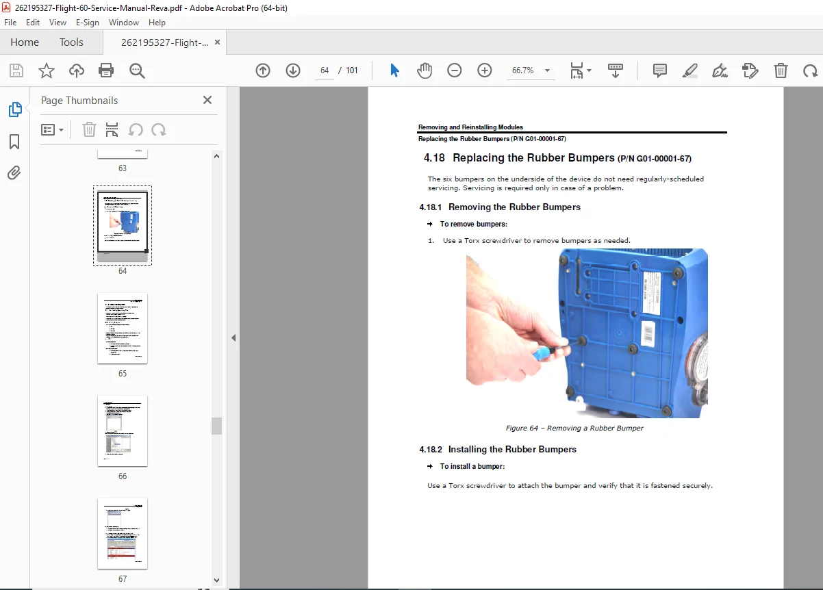
- Rubber Bumpers
- Removal procedure
- Installation protocol
CHAPTER 5: SOFTWARE MANAGEMENT
System Log Files:
- Downloading procedures for diagnostic data
- Log file interpretation
- Troubleshooting use of log data
Software Loading Procedures:
PCS (Pneumatic Control System):
- Update procedures
- Manifold S/N update protocol
- Hours meter reset procedures
- Verification testing
Main CPU:
- Firmware update procedures
- Version management
- Installation verification
- System testing post-update
Panel CPU:
- User interface software update
- Configuration procedures
- Touch screen calibration
- Functional verification
CHAPTER 6: OPERATION VERIFICATION PROCEDURE (OVP)
Required Equipment: Complete list of test equipment and standards required for OVP
Standard Ventilator Settings (STS):
- Baseline configuration for testing
- Parameter specifications
- Test lung requirements
Comprehensive Test Procedures:
Front Panel Self Test:
- LED indicator verification
- Button functionality testing
- Display verification
- Audio alarm testing
Pressure Sensors Calibration:
- Inspiratory pressure sensor calibration
- Expiratory pressure sensor calibration
- Calibration procedures and acceptance criteria
- Verification testing
Pressure Relief Calibration:
- Safety pressure relief verification
- Calibration procedures
- Functional testing
- Acceptance criteria
Volume Factor Calibration:
- Tidal volume calibration
- Flow measurement verification
- Accuracy testing
- Acceptance criteria
Comprehensive Performance Verification:
- All ventilation modes testing
- Alarm system verification
- Backup systems testing
- Battery performance verification
- Complete system integration testing
CHAPTER 7: MAINTENANCE
Regular Maintenance Procedures:
- Scheduled maintenance intervals
- Component inspection protocols
- Cleaning procedures
- Filter replacement schedules
- Sensor verification
- Battery maintenance
- Calibration verification schedules
- Performance testing requirements
Preventive Maintenance:
- Routine inspection checklists
- Component wear assessment
- Preemptive replacements
- System optimization
- Documentation requirements
CHAPTER 8: TROUBLESHOOTING
Systematic Troubleshooting:
- Problem identification methodologies
- Symptom-based diagnostic trees
- Component isolation procedures
- Test procedures for fault identification
Common Problems and Solutions:
- Alarm condition troubleshooting
- Power system issues
- Pneumatic system problems
- Sensor malfunctions
- Display and interface problems
- Software-related issues
Contact Information:
- FLIGHT MEDICAL technical support
- Service centers
- Emergency support procedures
- Part ordering information
CHAPTER 9: REPACKAGING AND SHIPPING
Return to Manufacturer Procedures:
- Proper packaging requirements
- Shipping preparation
- Documentation requirements
- RMA (Return Merchandise Authorization) procedures
- Tracking and follow-up
Safety & Compliance
Regulatory Requirements:
- Medical device classification
- Federal law restrictions (US) – physician order only
- Professional operator requirements (respiratory therapists)
- State law and regulation compliance
- Environmental use restrictions
Operator Qualifications:
- Respiratory therapist certification
- Proper training requirements
- Physician direction mandatory
- Competency verification
Installation & Use Restrictions:
- Not for use in presence of flammable anesthetics
- Grounded receptacle requirements only
- Emergency backup equipment mandatory
- Patient monitoring systems required
- Direct clinical observation essential
Who Should Use This Manual?
- Biomedical equipment technicians (BMETs) specializing in respiratory equipment
- Respiratory equipment service engineers
- Flight Medical authorized service technicians
- Hospital clinical engineering departments
- Home care equipment service providers
- Transport ventilator maintenance personnel
- Medical equipment repair specialists
Manual Features
✓ Official Flight Medical Innovations factory service manual
✓ 101 pages of comprehensive technical documentation
✓ 9 detailed chapters covering all service aspects
✓ Revision A (May 2011) – complete and updated
✓ Dual model coverage (Flight 60 and F60 Dual Limb)
✓ Step-by-step module replacement procedures
✓ Complete pneumatic and electrical diagrams
✓ Software management procedures (PCS, Main CPU, Panel CPU)
✓ Operation Verification Procedure (OVP) protocols
✓ Calibration procedures for all sensors
✓ Troubleshooting guides with solutions
✓ Preventive maintenance schedules
✓ Safety warnings and compliance information
✓ Detailed component illustrations
This service manual provides biomedical technicians with complete factory-level technical knowledge for maintaining and repairing Flight Medical Flight 60 Ventilators, ensuring safe and reliable operation of life-critical mechanical ventilation equipment used in hospitals, emergency transport, and home care environments.
FILE DETAILS
Manual Name: Flight Medical Flight 60 Ventilator Service Manual
Models Covered: Flight 60 Ventilator, F60 Dual Limb Ventilator
Year: May 2011 (Revision A)
Manual Quality: Excellent – Clear text, detailed diagrams, professional formatting
Number of Pages: 101 pages
File Format: PDF
File Size: 17.6 MB
Language: English
Publication Number: V60-00002-18 Rev. A
Revision: Rev. A (May 2011)
Publisher: Flight Medical Innovations Ltd.