Fuso Canter Body equipment mounting directives Service Manual – PDF DOWNLOAD
Original price was: $86.95.$29.95Current price is: $29.95.
Fuso Canter Body equipment mounting directives Service Manual – PDF DOWNLOAD
Description
Fuso Canter Body equipment mounting directives Service Manual – PDF DOWNLOAD
DESCRIPTION:
Fuso Canter Body equipment mounting directives Service Manual – PDF DOWNLOAD
INTRODUCTION :
Mitsubishi Fuso Truck and Bus Corp., as the manufacturer of Mitsubishi Fuso vehicles, publishes this body/ equipment mounting directive to provide body manufacturers with important technical information about the basic vehicle. This information must be observed by the body manufacturer in the production of bodies and equipment, fittings and modifications for Mitsubishi Fuso vehicles.
- Due to the large number of body manufacturers and body types, Mitsubishi Fuso Truck and Bus Corp. cannot take into account all the possible modifications to the vehicle, e.g. performance, stability, load distribution, center of gravity and handling characteristics, that may result from the design of attachments, bodies, equipment or modifications. For this reason, Mitsubishi Fuso Truck and Bus Corp. can accept no body manufacturer liability for accidents or injuries sustained as a result of such modifications to the vehicles if such modifications have a negative impact on the overall vehicle.
- Accordingly, Mitsubishi Fuso Truck and Bus Corp. will only assume liability as vehicle manufacturer within the scope of the design, production and instruction services which it has performed itself. The body manufacturer is bound to ensure that its bodies and equipment, fittings and modifications are themselves not defective, nor capable of causing defects or hazards to the overall vehicle.
- If this obligation is violated in any way, the body manufacturer shall assume full product liability. The body/equipment mounting directives enable Mitsubishi Fuso Truck and Bus Corp. to instruct the body manufacturer about important aspects that must be observed when mounting its bodies and equipment, fittings and modifications.
- These body/equipment mounting directives are primarily intended for the professional manufacturers of bodies, equipment, fittings and modifications for our vehicles. As a result, these body / equipment mounting directives assume that the body manufacturer has suitable background knowledge.
- If you intend to mount attachments, bodies and equipment on or carry out modifications to our vehicles, please be aware that certain types of work (e.g. welding work on load-bearing components) may only be carried out by qualified personnel. This will avoid the risk of injury while also ensuring that the degree of quality required for the attachments, bodies, equipment and modifications is given.
TABLE OF CONTENTS:
Fuso Canter Body equipment mounting directives Service Manual – PDF DOWNLOAD
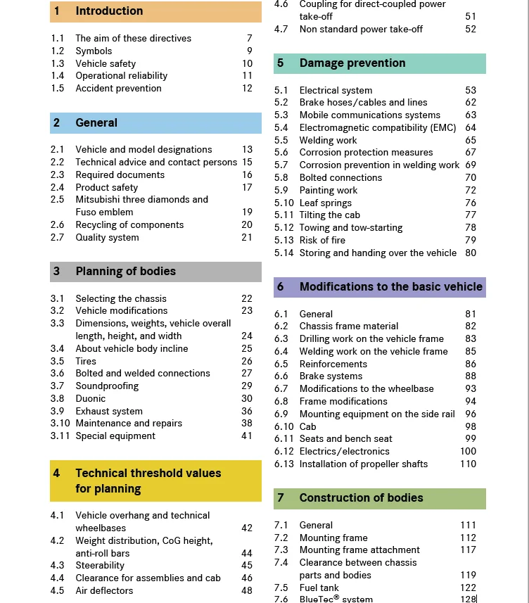
1 Introduction
1.1 The aim of these directives 7
1.2 Symbols 9
1.3 Vehicle safety 10
1.4 Operational reliability 11
1.5 Accident prevention 12
2 General
2.1 Vehicle and model designations 13
2.2 Technical advice and contact persons 15
2.3 Required documents 16
2.4 Product safety 17
2.5 Mitsubishi three diamonds and ?
Fuso emblem 19
2.6 Recycling of components 20
2.7 Quality system 21
3 Planning of bodies
3.1 Selecting the chassis 22
3.2 Vehicle modifications 23
3.3 Dimensions, weights, vehicle overall ?
length, height, and width 24
3.4 About vehicle body incline 25
3.5 Tires 26
3.6 Bolted and welded connections 27
3.7 Soundproofing 29
3.8 Duonic 30
3.9 Exhaust system 36
3.10 Maintenance and repairs 38
3.11 Special equipment 41
4 Technical threshold values ?
for planning
4.1 Vehicle overhang and technical ?
wheelbases 42
4.2 Weight distribution, CoG height, ?
anti-roll bars 44
4.3 Steerability 45
4.4 Clearance for assemblies and cab 46
4.5 Air deflectors 48
4.6 Coupling for direct-coupled power ?
take-off 51
4.7 Non standard power take-off 52
5 Damage prevention
5.1 Electrical system 53
5.2 Brake hoses/cables and lines 62
5.3 Mobile communications systems 63
5.4 Electromagnetic compatibility (EMC) 64
5.5 Welding work 65
5.6 Corrosion protection measures 67
5.7 Corrosion prevention in welding work 69
5.8 Bolted connections 70
5.9 Painting work 72
5.10 Leaf springs 76
5.11 Tilting the cab 77
5.12 Towing and tow-starting 78
5.13 Risk of fire 79
5.14 Storing and handing over the vehicle 80
6 Modifications to the basic vehicle
6.1 General 81
6.2 Chassis frame material 82
6.3 Drilling work on the vehicle frame 83
6.4 Welding work on the vehicle frame 85
6.5 Reinforcements 86
6.6 Brake systems 88
6.7 Modifications to the wheelbase 93
6.8 Frame modifications 94
6.9 Mounting equipment on the side rail 96
6.10 Cab 98
6.11 Seats and bench seat 99
6.12 Electrics/electronics 100
6.13 Installation of propeller shafts 110
7 Construction of bodies
7.1 General 111
7.2 Mounting frame 112
7.3 Mounting frame attachment 117
7.4 Clearance between chassis ?
parts and bodies 119
7.5 Fuel tank 122
7.6 BlueTec® system 128
8 Calculations
8.1 Axle load calculation 132
9 Technical data
9.1 Vehicle performance list 134
9.2 Performance curve 135
9.3 Weight distribution table 143
9.4 Chassis cab drawings 160
9.5 Frame layout 175
9.6 Spring diagram 187
9.7 Lamp layout drawings 199
9.8 Power train 201
9.9 Differential and tire bound height 202
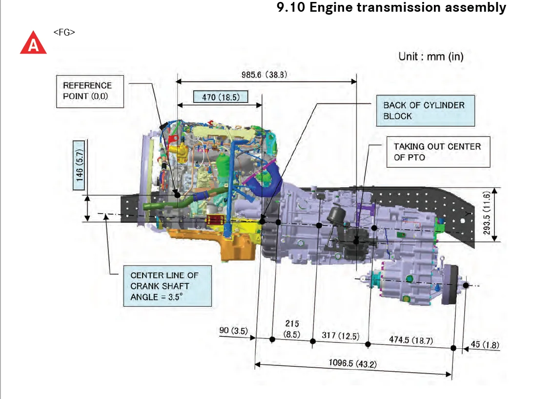
9.10 Engine transmission assembly 204
9.11 Transmission power-take-off layout 206
9.12 Battery mounting layout 208
9.13 Fuel tank mounting layout 209
9.14 BlueTec® exhaust gas ?
aftertreatment 212
9.15 Labels and marks 215
9.16 Electrical wiring diagram 219
IMAGES PREVIEW OF THE MANUAL:
FUSO CANTER BODY EQUIPMENT MOUNTING DIRECTIVES SERVICE MANUAL – PDF DOWNLOAD:
PLEASE NOTE:
- This is the SAME manual used by the dealers to troubleshoot any faults in your vehicle. This can be yours in 2 minutes after the payment is made.
- Contact us at [email protected] should you have any queries before your purchase or that you need any other service / repair / parts operators manual.
S.V