GB BST10 BST 10d Service Manual PDF Tower Collator Sheet Collating System PDF
Original price was: $65.00.$18.95Current price is: $18.95.
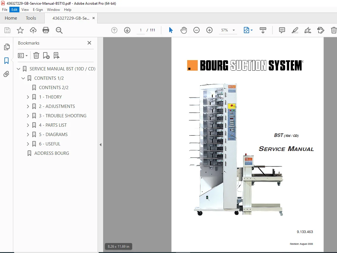
Official GB service manual for BST10, BST 10d, and BST 10 CD tower collating systems. This comprehensive 111-page technical manual (Part Number 9.133.463, Revision August 2006) covers theory of operation, mechanical and electrical adjustments, troubleshooting procedures, complete parts lists with exploded views, wiring diagrams, PCB schematics, and maintenance procedures for these high-speed sheet collating towers used in commercial printing and bindery operations for qualified service technicians.
Description
GB BST10 BST 10d Service Manual PDF Tower Collator Sheet Collating System – PDF DOWNLOAD
LONG DESCRIPTION
This is the official GB Service Manual for BST10 Series Tower Collators (Part Number 9.133.463, Revision August 2006), covering the BST 10, BST 10d (dual tower), and BST 10 CD models. This comprehensive 111-page technical manual provides complete service information for qualified service technicians to install, adjust, troubleshoot, maintain, and repair these professional tower collating systems used in commercial printing facilities, bindery operations, and high-volume document finishing environments worldwide.
Product Overview
GB BST10 Series Tower Collators:
The BST10 series represents professional tower collating solutions designed for high-speed gathering of printed sheets in sequential order. These modular tower systems combine precision sheet feeding, double-sheet detection, and intelligent bin control for reliable collating of multi-page documents, catalogs, magazines, brochures, and booklets in commercial printing and finishing operations.
Key Applications:
- Commercial printing facilities
- Print-for-pay shops
- In-plant print centers
- Bindery operations
- Book manufacturing
- Magazine production
- Catalog assembly
- Document finishing
- Direct mail production
- Packaging insert assembly
Models Covered
BST 10 – Single tower collating system
BST 10d – Dual tower collating system (two towers)
BST 10 CD – Split collating line configuration
All models feature modular bin construction with intelligent control systems for high-speed sheet gathering and collating operations.
Key Features and Technologies
Tower Configuration:
- 10 bin capacity per tower
- Modular bin design
- Individual bin clutch drives
- Automatic bin height adjustment
- Bin lifting/lowering motors
- Selectable bin operation
- Bin exclusion capability
Sheet Feeding System:
- Vacuum turbine pickup system
- Brushless turbine motors
- Adjustable suction control
- Air valve control system
- Top sheet separation mechanism
- Loading tray lifting mechanism
- In-built jogger system
Detection and Control:
- DMC (Double/Missfeed) detector
- 10 identical DMC boards (one per bin)
- Automatic calibration
- IR tacho disc cell
- Set output detector
- Empty bin detection
- Jam detection system
- Height monitoring cells
Sheet Handling:
- Front and rear joggers
- Exit roller system
- Jam detector
- Set reversal device
- Inter-tower conveyor system
- Delivery deflector
- Sheet overlap adjustment
Technical Specifications
Physical Specifications:
- Floor space requirements
- Tower dimensions
- Weight specifications
- Clearance requirements
- Access requirements
Performance Specifications:
- Collating speed range
- Sheet size capacity
- Paper weight range
- Production capacity
- Sets per hour capability
Electrical Specifications:
- Power requirements
- Voltage specifications
- Power consumption
- Fuse ratings
- RF filter
- Emergency stop system
Control System:
- Master board control
- Local processor (BPL – bin lifting/lowering)
- Slave logic (PL)
- PWM DAC (main motor and turbine control)
- DMC slave logic
- Keyboard interface
- LED status indicators
- Digital display
Comprehensive Manual Contents
DOCUMENT INFORMATION:
- Part Number: 9.133.463
- Revision: August 2006
- Publication Date: January 23, 2003 (original), August 25, 2006 (revised)
- Pages: 111 pages
- Page Size: A4 (595 x 842 pts)
- Languages: English (GB), German (D), French (F)
- Creator: QuarkXPress Passport
- Author: Chris
COMPLETE TABLE OF CONTENTS
SECTION 1: THEORY (Pages 1/1 to 1/10)
Components Location (Page 1/1): Complete component layout diagram showing:
- Tower Left Side:
- Rear side guide
- Conveyor locking acknowledgment switch
- DMC boards (10 identical boards, one per bin)
- Bin lifting/lowering motors (10 motors)
- Bin drive clutches (10 clutches)
- Emergency stop
- Keyboard
- Control boards location
- Main Control Boards:
- Local processor (BPL) – lifting/lowering control
- PWM DAC – main motor and turbines control
- Slave logic (PL)
- Master board
- Slave logic (DMC)
- Bottom Electrical Compartment:
- IR tacho disc cell
- Power to air valves (slave)
- Power to bin clutches (slave)
- Main motor assembly
- Brushless turbines
- Keyboard power supply
- Attachments control (CFS/4)
- Transformer
- 5V/12V chopped power board (with 2A fuse)
- Main motor drive (PWM-POW)
- Power interrupt (with relays)
- Power inlet
- Power ON/OFF switch
- Fuses
- RF filter
- Dual Tower Configuration:
- Collating line split-up (CUT)
- Left output enable
- Umbilical cord connections
- Inter-tower connectivity
Operation Instructions Summary (Page 1/2): Complete control panel guide:
- Multi-Tower Switch-On
- Emergency Stop (ARRET D’URGENCE/NOODSTOP)
- Start/Stop Controls:
- Push on/push off key
- BELT display indication
- Green LED in start key
- Status LEDs:
- Red LED (blinks during calibration)
- Green LED (run status)
- Warning indicators
- Calibration Mode:
- CALIBR key
- DMC automatic calibration
- First set stops for visual check
- Alarm Indicators:
- JAM (jam at delivery)
- MISS (missing sheet detection)
- DOUBLE (double sheet detection)
- EMPTY (empty bin indication)
- Bin Control:
- Bin selection (up to 5 bins selectable)
- Bin exclusion and skipping
- Green LED: bin excluded
- Green/red LED blinking: excluded bin in selected batch
- Display shows exclusion step and excluded bin count
- OUT: overflow + clear
- Operating Modes:
- Conveyor on/off
- Air level adjustment mode
- SET COUNTER/PRESET + QTY
- Display Functions:
- Total of sets
- Selected bins
- Preset number of sets
- Sheets overlap (in mm)
- Error messages (ACC, JAM, CELL, CAL, MOT, EMPT)
- Keypad Functions:
- ENTER – Instructions confirmation
- CLEAR – Instructions cancellation, counter reset
- 0-9 – Numeric entry
- SELECT – Bins selection
- PRESET – Quantity preset
- INSERT – Automatic interleaving
- SKIP – Bin skipping
- PROGRAM – Program scrolling
- Advanced Functions:
- Tray lifting/lowering
- Conveyor speed increase/decrease
- Tower rank search
- Automatic adjacent bin selection (SUC=3, BLO=2)
- 8 collating modes
- Program position (A=automatic use)
- Total working hours display
- Instantaneous sets/hour display
- Tower splitting capability
- Overlap adjustment (7 steps)
Meaning of LEDs (BST 10) (Page 1/3):
- LED indicator functions
- Status indications
- Alarm conditions
- Operational states
Meaning of LEDs (BST 10d) (Page 1/4):
- Dual tower LED functions
- Additional indicators
- Tower-specific status
- Inter-tower communication status
Floor Space Requirements and Specifications (Page 1/5):
- Installation footprint
- Clearance specifications
- Access requirements
- Mounting requirements
- Environmental specifications
Software History (BST 10) (Pages 1/6 to 1/9): Complete software revision history including:
- Version numbers
- Release dates
- Software changes
- Bug fixes
- Feature additions
- Compatibility notes
- Upgrade procedures
- Software 6.08 features (bins selection inhibit)
Hardware History (Page 1/10):
- Hardware revision tracking
- Component changes
- PCB revisions
- Mechanical modifications
- Retrofit information
SECTION 2: ADJUSTMENTS (Pages 2/1 to 2/8)
Mechanical Adjustments:
Bins Clutch Drive Toothed Belt Tension (Page 2/1):
- Belt tension specifications
- Tension measurement procedures
- Adjustment procedures
- Tension verification
- Belt wear inspection
Bins Clutch Drive Toothed Belt Replacement and Positioning (Page 2/2):
- Belt removal procedures
- Belt selection specifications
- Installation procedures
- Belt tracking alignment
- Tensioning procedures
- Verification tests
Electrical Adjustments:
P.C. Boards Addressing (BST 10 & BST 10d) (Page 2/3):
- Board address configuration
- DIP switch settings
- Address assignment procedures
- Multi-tower addressing
- Address verification
Setting Specific to Interleave Sheet (Insert) (Page 2/4):
- Interleave mode configuration
- Insert timing adjustment
- Insert bin selection
- Insert detection setup
- Function verification
Turbine Speed Range Arrangement (Page 2/5):
- Speed range configuration
- RPM adjustment procedures
- Speed sensor calibration
- Optimal speed determination
- Speed verification tests
Pulses Shaping (Page 2/7):
- Encoder pulse adjustment
- Signal conditioning
- Pulse width optimization
- Noise filtering
- Signal verification
Delivery Cell Sensitivity Threshold Adjustment (Page 2/8):
- Detection threshold settings
- Sensitivity calibration
- False detection elimination
- Detection verification
- Adjustment procedures
SECTION 3: TROUBLESHOOTING (Pages 3/1 to 3/9)
Check Panel (Page 3/1):
- Diagnostic LED interpretation
- Status indicators
- Fault code display
- Control panel testing
- Button function verification
Back-up Battery (Page 3/2):
- Battery location
- Battery testing
- Voltage verification
- Replacement procedures
- Memory retention testing
Double Sheet Feed Detector (Page 3/3):
- DMC sensor testing
- Calibration verification
- Sensitivity adjustment
- Detection accuracy testing
- Sensor cleaning procedures
Ghost Double Sheet Feeds (Page 3/4):
- False detection troubleshooting
- Electrical noise sources
- Sensor alignment verification
- Threshold adjustment
- Elimination procedures
Loading Trays Lifting Cells Disturbing (Page 3/5):
- Sensor interference diagnosis
- Alignment verification
- Electrical noise elimination
- Signal integrity testing
- Corrective procedures
Matching Towers and Jogger (Page 3/6):
- Tower synchronization
- Jogger timing adjustment
- Sheet alignment verification
- Inter-tower communication
- Timing optimization
Picking of the Sheets (Page 3/7):
- Vacuum level verification
- Suction head inspection
- Air valve testing
- Turbine performance check
- Sheet separation optimization
Vacuum and Pressure Levels at Turbine(s) Intake-Output (Page 3/8):
- Vacuum measurement procedures
- Pressure specifications
- Turbine performance testing
- Air flow verification
- Adjustment procedures
Poor Sheets Picking (Page 3/9):
- Symptom-based diagnosis
- Vacuum system troubleshooting
- Mechanical adjustments
- Air valve verification
- Solution procedures
SECTION 4: PARTS LIST (Pages 4/1 to 4/26)
Complete Illustrated Parts Breakdown:
(Dwg ref. 1) Boards – Fuses – Others (Page 4/1):
- PCB assemblies with part numbers
- Fuse specifications
- Control boards
- Power supply boards
- Miscellaneous electrical components
(Dwg ref. 2) Bin Controls (DMC + Empty + Height) (Page 4/2):
- DMC board assemblies
- Empty detection sensors
- Height monitoring cells
- Associated hardware
- Mounting components
(Dwg ref. 3) Sets Exit Roller + Jam Detector + Rear Jogger (Page 4/3):
- Exit roller assembly
- Jam detection sensors
- Rear jogger mechanism
- Drive components
- Mounting hardware
(Dwg ref. 4) Main Drive Motor (Page 4/4):
- Main motor assembly
- Motor specifications
- Mounting components
- Drive coupling
- Associated hardware
(Dwg ref. 5) Bottom Electrical Compartment (Page 4/5):
- Power supply components
- Control board mounting
- Cable harnesses
- Fuse holders
- Electrical connections
(Dwg ref. 6) Delivery Unit Assembly (Main Tower BST 10/d) (Page 4/6):
- Delivery mechanism
- Roller assemblies
- Drive components
- Mounting hardware
- Associated parts
(Dwg ref. 7) L.H. Delivery Unit Assembly (BST 10d) (Page 4/7):
- Left-hand delivery for dual towers
- Roller configuration
- Drive system
- Mounting components
(Dwg ref. 7 bis) Delivery Unit Assembly ADDITIONAL (Page 4/8):
- Additional delivery components
- Optional configurations
- Upgrade parts
(Dwg ref. 8) Bin + Exit Deflector (Page 4/9):
- Bin assembly components
- Deflector mechanism
- Guide plates
- Adjustment hardware
- Mounting components
(Dwg ref. 9) Set Reversal Device (BST 10/10d) (Page 4/10):
- Reversal mechanism assembly
- Drive components
- Sensors
- Guide system
- Associated hardware
(Dwg ref. 10) Inter Tower Conveyor (BST 10/10 CD) (Page 4/11):
- Conveyor assembly
- Drive system
- Belt components
- Tensioning system
- Mounting hardware
(Dwg ref. 11) Inter Tower Conveyor (BST 10 dual) (Page 4/12):
- Dual tower conveyor
- Transfer mechanism
- Drive system
- Mounting components
(Dwg ref. 12) Sheets Pick Up Device (Page 4/13):
- Suction head assembly
- Vacuum manifold
- Air control valves
- Mounting hardware
- Associated components
(Dwg ref. 13) Suction Control Air Valve (Page 4/14):
- Air valve assembly
- Control solenoids
- Mounting hardware
- Air line fittings
- Associated components
(Dwg ref. 14) Door (Operator Side) (Page 4/15):
- Access door assembly
- Hinges and latches
- Safety switches
- Associated hardware
(Dwg ref. 14 bis) Control Panel (Page 4/16):
- Control panel assembly
- Keyboard components
- Display unit
- LED indicators
- Mounting hardware
(Dwg ref. 15) Loading Tray Lifting (Page 4/17):
- Tray lift mechanism
- Lifting motor
- Guide system
- Height sensors
- Associated hardware
(Dwg ref. 16) In Built Jogger (Page 4/18):
- Jogger assembly
- Drive mechanism
- Guide plates
- Adjustment components
- Mounting hardware
(Dwg ref. 17) Top Sheet Separation (Page 4/19):
- Separation mechanism
- Air jets
- Blower assembly
- Control components
- Associated hardware
(Dwg ref. 18) Belt Transmission (Page 4/20):
- Belt drive assemblies
- Pulleys and tensioners
- Drive belts
- Mounting hardware
- Associated components
Index Parts List with Recommended Ones (Pages 4/21 to 4/26):
- Complete alphabetical parts index
- Part numbers
- Descriptions
- Quantities
- Recommended spare parts
- Replacement intervals
- Cross-reference information
SECTION 5: DIAGRAMS (Pages 5/2 to 5/25)
Block Diagram (BST 10 & BST 10d) (Page 5/2):
- System overview
- Component interconnections
- Signal flow
- Control hierarchy
Wiring Power Supplies (BST 10) (Pages 5/3 to 5/4):
- AC power distribution
- DC power circuits
- Power supply schematics
- Fusing and protection
- Ground connections
Wiring Power Supplies (BST 10d) (Pages 5/5 to 5/6):
- Dual tower power distribution
- Additional power circuits
- Inter-tower power connections
- Load distribution
Wiring: Looms (Pages 5/7 to 5/10):
- Cable harness routing
- Connector pinouts
- Wire color codes
- Connection diagrams
- Cable specifications
Interlock/Power Enable Circuit (BST 10) (Pages 5/11 to 5/12):
- Safety interlock system
- Power enable logic
- Door switch circuits
- Emergency stop circuit
- Safety relay configuration
Interlock Loop in Main Towers (BST 10d) (Page 5/13):
- Main tower interlock system
- Safety chain
- Sensor integration
Interlock Loop in Additional Tower (BST 10d) (Page 5/14):
- Additional tower interlocks
- Safety continuity
- System integration
Finishing Attachments Drive Board (CFS 3 and 4) (Page 5/15):
- Attachment control circuits
- CFS board schematic
- Interface connections
- Control signals
Empty Cell Principle Diagram and Component Location (Page 5/16):
- Empty detection system
- Sensor circuit
- Component layout
- Signal processing
Set Output Detector (Page 5/17):
- Detection circuit
- Sensor type
- Signal conditioning
- Output interface
PWM + DAC Principle Diagram (Page 5/18):
- Pulse width modulation circuit
- Digital-to-analog conversion
- Speed control system
- Signal generation
PWM DAC PCB Layout (Page 5/19):
- Board component layout
- Connector locations
- Test points
- Component identification
PWM + POW Main Motor Power Supply (Page 5/20):
- Motor drive circuit
- Power amplification
- Protection circuits
- Feedback systems
Slave Logic PCB (Page 5/21):
- Slave board schematic
- Logic circuits
- Interface connections
- Component layout
BIG-PL Principle Diagram (Pages 1/3, 2/3, 3/3) (Pages 5/22 to 5/24):
- Complete BIG-PL schematic (3 pages)
- Master control logic
- Processing circuits
- I/O interface
- Communication buses
BIG-PL Component Location (Page 5/25):
- PCB component layout
- Connector identification
- Test point locations
- Jumper positions
- LED indicators
SECTION 6: USEFUL, TRANSLATED AND OBSOLETE ITEMS (Pages 6/1 to 6/20)
German Language (D) Section:
- Gebrauchsanweisung Überblick (Page 6/1) – Operation instructions summary
- Spannung des langen, gezahnten Antriebsriemens (Page 6/2) – Belt tension
- Einrichten der Geschwindigkeitsspanne der Turbinen (Pages 6/3 to 6/4) – Turbine speed adjustment
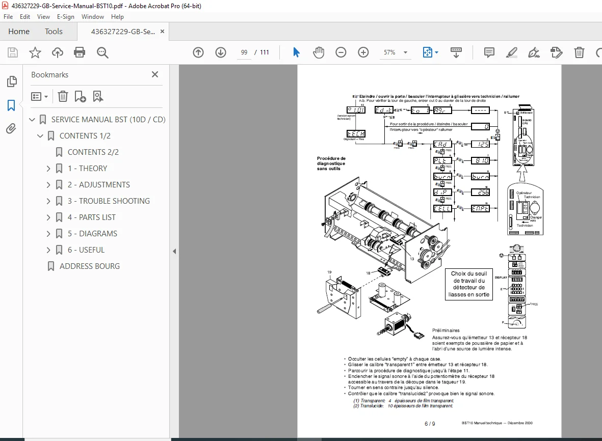
- Werkzeugsfreie Störungshilfe (Page 6/5) – Tool-less troubleshooting
French Language (F) Section:
- Mode d’emploi résumé (Page 6/6) – Operation instructions summary
- Vitesse turbine (Pages 6/7 to 6/8) – Turbine speed
- Procédure de diagnostique sans outils (Pages 6/9, 6/11) – Tool-less diagnostic procedures
- Procédure rapide de contrôle (Page 6/10) – Quick check procedure
- Procédure de réglage des amplificateurs tacho (Page 6/12) – Tacho amplifier adjustment
- DELs signification de leur allumage (Pages 6/13 to 6/14) – LED meaning
English (GB) Section – Additional Information:
- In-built Jogger in Retrofit Kit Form (Pages 6/15 to 6/16) – Jogger upgrade
- Check Panel (BST10) (Page 6/17) – Diagnostic panel information
- Turbine Speed Range Arrangement (Page 6/18) – Speed configuration
- Software History (BST 10d) (Page 6/19) – Dual tower software
- Toolless Encoder Pulses Shaping (Page 6/20) – Pulse adjustment procedures
Who Needs This Manual?
This GB BST10 collator service manual is essential for:
- Print shop service technicians
- Bindery equipment technicians
- Commercial printing facility maintenance staff
- GB authorized service centers
- Equipment service companies
- Print production supervisors
- Anyone servicing GB collating systems
Prerequisites:
✓ GB equipment service training
✓ Mechanical repair experience
✓ Electrical troubleshooting skills
✓ Understanding of vacuum systems
✓ Sheet feeding system knowledge
✓ Control system diagnostics
✓ Pneumatic system experience
✓ Print finishing operations familiarity
FILE DETAILS
| Detail | Specification |
|---|---|
| Manual Title | BST (10d / CD) SERVICE MANUAL |
| Models Covered | BST 10, BST 10d, BST 10 CD |
| Part Number | 9.133.463 |
| Revision | August 2006 |
| Original Creation | January 23, 2003 |
| Last Modified | August 25, 2006 |
| Manufacturer | GB (Graphic Binding) |
| Pages | 111 pages |
| PDF Quality | High-quality technical manual with detailed diagrams |
| File Size | 14.0 MB |
| Page Size | A4 (595 x 842 pts) |
| Languages | English, German, French |
| Creator | QuarkXPress Passport |
| Author | Chris |
| PDF Version | 1.3 |