GE CARESCAPE ONE Patient Monitor Service Manual Calibration Repair Guide PDF
Original price was: $95.00.$28.95Current price is: $28.95.
Complete factory service manual for GE Healthcare CARESCAPE ONE patient monitoring system covering software version 3.2 and hardware version 1. Comprehensive technical documentation includes installation, configuration, calibration procedures, troubleshooting, electrical safety testing, parameter modules (ECG, SpO2, NIBP, CO2, rSO2), battery maintenance, and checkout procedures. Essential professional reference for biomedical engineers and clinical equipment technicians servicing hospital patient monitors.
Description
GE CARESCAPE ONE Patient Monitor Service Manual Calibration Repair Guide PDF DOWNLOAD
DESCRIPTION
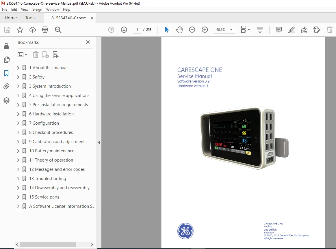
This is the complete official GE CARESCAPE ONE Service Manual (Document 5825339, 2nd Edition, February 2021) for the CARESCAPE ONE patient monitoring system. This comprehensive factory service manual provides professional-grade installation, configuration, calibration, and troubleshooting information for authorized biomedical engineers and clinical equipment technicians servicing this advanced hospital patient monitor.
Equipment Covered by This Service Manual
GE Healthcare CARESCAPE ONE Patient Monitor:
- Software Version: 3.2
- Hardware Version: 1
- Manufacturer: GE Medical Systems Information Technologies, Inc. / GE Healthcare Finland Oy
- Application: Hospital patient monitoring
- Type: Multi-parameter vital signs monitor
CARESCAPE ONE System Components:
Main Monitor Unit:
- CARESCAPE ONE display and processing unit
- Touchscreen interface
- Integrated battery power
- Network connectivity
- USB ports
CARESCAPE Parameters:
- Modular measurement capabilities
- Multiple parameter modules supported
- Hot-swappable design
CARESCAPE ECG:
- Electrocardiogram monitoring
- Multiple lead configurations
- Arrhythmia detection
- ST segment analysis
CARESCAPE Pressure:
- Invasive blood pressure monitoring
- Multiple pressure channels
- Zero calibration capability
CARESCAPE Temperature:
- Patient temperature monitoring
- Multiple sensor inputs
- Core and peripheral monitoring
CARESCAPE SpO2 Devices:
- Pulse oximetry monitoring
- Masimo SET SpO2 technology
- Nellcor with OxiMax technology
- Multiple sensor compatibility
CARESCAPE rSO2 — INVOS:
- Regional oxygen saturation monitoring
- Cerebral oximetry
- Non-invasive tissue oxygenation
CARESCAPE CO2 Devices:
- Capnography monitoring
- LoFlo CO2 (low flow)
- Microstream CO2 technology
- End-tidal CO2 measurement
CARESCAPE NIBP:
- Non-invasive blood pressure
- Oscillometric measurement
- Multiple cuff sizes
- Automated cycling
Docking Solutions:
- CARESCAPE Dock F0 (full dock with power supply)
- Mini Dock (compact mounting)
- Parameter Docks (modular expansion)
Complete Manual Contents (258 Pages)
This GE CARESCAPE ONE service manual PDF is organized into comprehensive chapters covering all service aspects:
CHAPTER 1: ABOUT THIS MANUAL
1.1 Intended Use of This Manual
- Service and maintenance guidance
- Professional biomedical technician reference
- Authorized service personnel only
1.2 Intended Audience
- Biomedical engineers
- Clinical equipment technicians
- GE Healthcare authorized service personnel
- Hospital maintenance staff (authorized)
1.3 Manual Conventions
Monitor Naming Conventions:
- CARESCAPE ONE terminology
- Component identification
- Module nomenclature
Other Naming Conventions:
- Standard terminology
- Abbreviations
- Technical terms
1.4 Illustrations and Names
- Visual reference guide
- Component identification
- Connector locations
1.5 Related Documents
- User manuals
- Technical specifications
- Installation guides
- Regulatory documentation
1.6 Revision History
- 1st Edition documentation
- 2nd Edition updates (2021-02-22)
- Software version tracking
1.7 Product Availability
- Regional variations
- Configuration options
1.8 Trademarks
- GE Healthcare trademarks
- Third-party trademarks (Masimo, Nellcor, INVOS)
1.9 Manufacturer Responsibility
- Product innovation disclaimer
- Specification change notice
- Technical documentation accuracy
CHAPTER 2: SAFETY
2.1 Safety Message Signal Words
- WARNING: Risk of injury or death
- CAUTION: Risk of equipment damage
- NOTE: Important information
2.2 Safety Symbols
- IEC 60601-1 symbols
- Warning symbols
- Information symbols
2.3 System Safety
- Electrical safety requirements
- Patient safety considerations
- Operator safety guidelines
- Service precautions
CHAPTER 3: SYSTEM INTRODUCTION
3.1 Short Description of Equipment
- Patient monitoring system overview
- Multi-parameter vital signs monitoring
- Hospital critical care application
3.2 Software
- Version 3.2 features
- Operating system
- Application software
3.3 Battery
- Lithium-ion battery technology
- Hot-swappable design
- Charging system
- Battery management
3.4 CARESCAPE ONE System Components Complete component overview
3.5 CARESCAPE Parameters
- Modular parameter design
- Multiple measurement capabilities
- Parameter identification
3.6 CARESCAPE ECG
- Lead configurations (3, 5, 12-lead capability)
- Monitoring modes
- Diagnostic capabilities
- Arrhythmia detection
3.7 CARESCAPE Pressure
- Invasive pressure channels
- Zeroing procedures
- Transducer compatibility
3.8 CARESCAPE Temperature
- Temperature measurement methods
- Sensor types
- Multiple input channels
3.9 CARESCAPE SpO2 Devices
SpO2 Equipment Connection:
- Cable routing
- Sensor compatibility
- Signal quality optimization
Masimo SET SpO2:
- Signal Extraction Technology
- Motion tolerance
- Low perfusion performance
- Equipment connection procedures
Nellcor OxiMax Technology:
- OxiMax algorithm
- Sensor compatibility
- Connection procedures
Pulse Oximetry Measurement Principle:
- Light absorption technology
- Hemoglobin oxygen saturation
- Pulse detection
- Artifact rejection
3.10 CARESCAPE rSO2 — INVOS
- Regional oxygen saturation
- Near-infrared spectroscopy
- Sensor placement
- Cerebral monitoring
3.11 CARESCAPE CO2 Devices
LoFlo CO2:
- Low flow capnography
- Neonatal/pediatric applications
- Sidestream technology
Microstream CO2:
- Ultra-low sample flow
- Mainstream alternative
- Minimal dead space
3.12 Non-invasive Blood Pressure Measurement
Device Compatibility:
- Cuff size selection
- Patient population
- Measurement intervals
NIBP Equipment Connection:
- Cuff connection
- Hose routing
- Leak prevention
NIBP Measurement Principle:
- Oscillometric method
- Cuff inflation/deflation
- Pulse detection
- Pressure determination
3.13 Docks
CARESCAPE Dock F0:
- Full-featured docking station
- Integrated power supply
- Battery charging
- Parameter module support
- Mounting capabilities
Mini Dock:
- Compact design
- Basic mounting
- Power connection
Parameter Docks:
- Modular expansion
- Additional parameter capacity
3.14 Controls and Connectors
CARESCAPE ONE Views:
- Front panel layout
- Back panel connections
- Side view connectors
- Access ports
CARESCAPE Dock F0 Views:
- Side view details
- Connector locations
- Module slots
CO2 Device Connectors:
- Microstream connections
- Gas sampling ports
- Indicators
rSO2 INVOS Connectors:
- Sensor connections
- Status indicators
3.15 Indicators
Power Status Indicator:
- Power on/off states
- Standby mode
- Error conditions
Battery Status Indicator:
- Charge level
- Charging status
- Low battery warning
3.16 Standards Compliance
IEC 60601-1:
- Medical electrical equipment safety
- Patient protection
- Electrical safety requirements
IEC 60601-1-2:
- Electromagnetic compatibility (EMC)
- Immunity requirements
- Emission limits
IEC 60529:
- Ingress protection rating
- Liquid protection
- Solid particle protection
3.17 Equipment Symbols
- Comprehensive symbol guide
- Warning symbols
- Information symbols
- Connector symbols
- Standards symbols
3.18 Unique Device Identifier (UDI)
- UDI location
- Barcode information
- Device identification
3.19 Equipment Identification
- Serial number location
- Model identification
- Rating plate information
3.20 User Interface Indicators
- Display symbols
- Status indicators
- Alarm indicators
3.21 Service Requirements
- Authorized service only
- Qualified personnel
- Special tools required
3.22 Masimo SpO2 Safety Precaution
- Specific safety requirements
- Installation precautions
3.23 Product Security
- Cybersecurity features
- Network security
- Access control
CHAPTER 4: USING THE SERVICE APPLICATIONS
4.1 Introduction to Service Applications
- Service software overview
- Access methods
- Security features
4.2 CARESCAPE First Use Wizard
- Initial setup procedures
- Configuration guidance
- Setup completion
4.3 CARESCAPE Service Interface
- Web-based service tool
- Configuration management
- Calibration access
- Diagnostic functions
4.4 User Accounts and Passwords
- Service account levels
- Password requirements
- Access control
4.5 Accessing Service Applications with Service PC
Network Configuration:
- Service PC network settings
- IP address configuration
- Connectivity verification
Supported Web Browsers:
- Compatible browsers
- Version requirements
- Security settings
Secure Access:
- HTTPS connections
- Certificate validation
- Encrypted communications
Local Access with Service PC:
- Direct Ethernet connection
- Local network access
- Configuration procedures
4.6 Accessing Service Calibrations
- Calibration menu access
- Parameter selection
- Procedure initiation
CHAPTER 5: PRE-INSTALLATION REQUIREMENTS
5.1 Unpacking
- Package inspection
- Component verification
- Damage assessment
5.2 Pre-Installation Checklist
- Site preparation
- Component inventory
- Tool requirements
5.3 System Compatibility
- Network infrastructure
- Power systems
- Mounting compatibility
5.4 Mounting Solutions
- Wall mount options
- Mobile cart mounting
- Desk/shelf mounting
- Ceiling mount systems
5.5 Power and Environmental Requirements
Power Requirements:
- Voltage specifications (typically 100-240V AC)
- Frequency (50/60 Hz)
- Current consumption
- Power cord specifications
Environmental Requirements:
- Operating temperature range
- Storage temperature range
- Humidity tolerance
- Altitude limitations
- Ventilation requirements
Electromagnetic Compatibility Precautions:
- EMI/RFI considerations
- Interference sources
- Installation guidelines
CHAPTER 6: HARDWARE INSTALLATION
6.1 Hardware Installation Overview
- Installation sequence
- Safety precautions
- Required tools
6.2 Masimo SpO2 Safety Precautions
- Critical installation requirements
- Connection procedures
6.3 Installing Batteries
Testing Battery Charge:
- Pre-installation testing
- Charge level verification
Inserting/Removing Battery:
- Battery compartment access
- Installation procedure
- Removal technique
- Safety locks
Checking Battery Charge with Software:
- Software battery monitor
- Charge status display
6.4 Installing CARESCAPE Dock F0
- Mounting procedure
- Electrical connections
- Module installation
6.5 Mounting Dock F0 Power Supply
- Power supply installation
- Cable routing
- Strain relief
6.6 Mounting CARESCAPE ONE
- Monitor installation to dock
- Securing mechanisms
- Connection verification
6.7 CARESCAPE Parameter Assembly
- Module identification
- Slot assignment
- Insertion procedure
6.8 Installing USB Patient Cable
- Cable routing
- Connection procedures
- Secure attachment
6.9 Installing CARESCAPE Parameters
- Parameter module installation
- Hot-swap procedures
- Recognition verification
6.10 Mounting CO2 Devices
- LoFlo CO2 installation
- Microstream installation
- Gas sampling line connection
6.11 Mounting rSO2 INVOS
- INVOS module installation
- Sensor cable management
6.12 Connecting CO2 to Anesthesia Cart Exhaust
- Scavenging system connection
- Gas disposal
- Safety considerations
6.13 Connecting to Mains Power
- Power cord connection
- Ground verification
- Power-up sequence
6.14 Masimo SpO2 Safety Precaution (Final verification)
CHAPTER 7: CONFIGURATION
7.1 Platform Configuration
- Initial system setup
- Hardware recognition
7.2 Configuring Date and Time
- Time zone selection
- NTP synchronization
- Manual setting
7.3 Setting Power Frequency
- 50 Hz / 60 Hz selection
- Line frequency matching
7.4 Selecting Language and Locale
- Language options
- Regional settings
- Units of measurement
7.5 Configuring Modules
- Parameter module setup
- Module-specific settings
7.6 Configuring ECG Filter
- Filter settings
- Noise reduction
- Diagnostic mode
7.7 Host Asset Settings
Asset Number Configuration:
- Hospital asset tracking
- Inventory management
Serial Number Configuration:
- Factory serial number
- Verification procedures
7.8 Password Management
User Accounts and Passwords:
- Service account creation
- Access levels
- Account management
Password Policy:
- Complexity requirements
- Expiration periods
- Security standards
Changing Passwords:
- Password change procedure
- Current password verification
Resetting Passwords:
- Administrative reset
- Default password restoration
7.9 Restarting the Monitor
- Soft restart
- Hard restart
- Post-restart verification
7.10 Settings Management
Settings Transfer Process:
- Export/import procedures
- Backup creation
- Settings deployment
Downloading Clinical and Platform Settings:
- Configuration download
- File management
- Storage location
Activating Settings:
- Configuration activation
- Verification procedures
- Rollback capability
Resetting to Factory Settings:
- Factory reset procedure
- Data preservation warnings
- Confirmation requirements
7.11 License Management
- Software license activation
- Feature enablement
- License verification
Software Packages:
- Optional features
- Add-on modules
- License key entry
7.12 Backup and Restore
Making a Backup:
- Configuration backup
- Data export
- Backup scheduling
Restoring a Backup:
- Restoration procedure
- Version compatibility
- Validation
7.13 Certificate Management
Creating Certificate Signing Request (CSR):
- SSL/TLS certificates
- Security implementation
Installing Certificate:
- Certificate import
- Validation
Viewing Current Certificate:
- Certificate details
- Expiration monitoring
7.14 Software Management
CARESCAPE Parameters Software:
- Module firmware
- Update procedures
Software Signing:
- Digital signatures
- Authentication verification
Software Upload:
- Update file transfer
- Installation preparation
Software Activation:
- Activation procedures
- Version verification
Uploading and Activating Host Software:
- System software updates
- Installation sequence
- Post-update testing
CHAPTER 8: CHECKOUT PROCEDURES
8.1 About Checkout Procedures
- Purpose of checkout
- Frequency requirements
- Documentation
8.2 Installation Check
- Post-installation verification
- New installation checklist
- Component testing
8.3 Planned Maintenance Check
- Preventive maintenance schedule
- Periodic testing
- Performance verification
8.4 Corrective Maintenance Check
- Post-repair verification
- Problem resolution confirmation
- Return-to-service criteria
8.5 Checking User and Service Manuals
- Documentation availability
- Current revision verification
8.6 Performing Visual Inspection
- Physical condition assessment
- Connector inspection
- Cable damage check
- Enclosure integrity
8.7 Performing Electrical Safety Tests
Test Setup:
- Required test equipment
- Safety analyzer connection
- Ground reference
Verifying Power Outlets:
- Outlet wiring verification
- Ground integrity
- Voltage verification
Verifying Power Cords and Plugs:
- Visual inspection
- Continuity testing
- Insulation resistance
About Leakage Current:
- Leakage current limits
- Measurement principles
- IEC 60601-1 requirements
Ground Leakage Current Testing:
- Test procedure
- Acceptance criteria
- Documentation
Chassis Leakage Current Tests:
- ePort connection testing
- Ethernet connection testing
- Multiple test points
Patient Leakage Current Tests:
- Source leakage testing
- Sink leakage testing (system and single parameter)
- Applied part testing
- Acceptance limits
Completing Electrical Safety Tests:
- Test documentation
- Pass/fail criteria
- Record keeping
8.8 Performing Functional Check of System
Preparation:
- Test setup
- Configuration verification
- Simulator connection
Testing Alarm Light:
- Visual alarm verification
- Color accuracy
- Intensity levels
Checking Startup:
- Boot sequence
- Self-test completion
- Error detection
Checking Display:
- Screen quality
- Touchscreen response
- Contrast adjustment
Checking CARESCAPE Parameters Identification:
- Module recognition
- Serial number verification
- Configuration validation
Checking Status of Connected Devices:
- Parameter module status
- SpO2 device identification and connection status (Masimo)
- rSO2 INVOS identification and connection status
- Battery charging verification
8.9 Performing Functional Check of Measurement Parameters
Required Tools:
- Patient simulator (e.g., ProSim 8)
- Pressure manometer
- CO2 gas calibration system
- INVOS Field Test Device
- Test cables and adapters
Making Connections:
- ECG simulator connection
- Pressure simulation setup
- Temperature simulation
- SpO2 simulation
- rSO2 test device connection
- CO2 calibration setup
- NIBP cuff connection
Battery Status Check (INVOS Field Test Device)
Configuring Monitor for Testing:
- Parameter selection
- Alarm limits
- Display setup
Configuring Simulator/Manometer:
- Output selection
- Value settings
- Waveform generation
Parameter Testing:
Testing ECG Measurement:
- Multiple lead testing
- Heart rate accuracy
- Waveform quality
- ST segment analysis
Testing Impedance Respiration:
- Respiratory rate accuracy
- Waveform quality
Testing Invasive Pressure:
- Zero verification
- Pressure accuracy
- Multiple channel testing
- Waveform quality
Testing Temperature:
- Accuracy verification
- Multiple channel testing
Testing SpO2:
- Oxygen saturation accuracy
- Pulse rate accuracy
- Plethysmograph waveform
- Low perfusion testing
Testing rSO2:
- INVOS measurement verification
- Sensor recognition
- Accuracy testing
Testing LoFlo CO2:
- End-tidal CO2 accuracy
- Respiratory rate
- Waveform quality
Testing Microstream CO2:
- EtCO2 accuracy
- Capnography waveform
- Sampling line integrity
Testing NIBP:
- Systolic/diastolic/MAP accuracy
- Multiple cuff sizes
- Leak testing
- Overpressure protection
Testing Analog Output and Defib Sync:
- Signal output verification
- Defibrillator synchronization
- Marker pulse testing
8.10 Zeroing LoFlo CO2 to Room Air
- Required tools
- Connection procedures
- Monitor configuration
- Zeroing procedure
- Verification
8.11 Completing Functional Check
- Documentation completion
- Service record creation
- Return to service
CHAPTER 9: CALIBRATION AND ADJUSTMENTS
9.1 Calibration and Adjustments Overview
- Calibration philosophy
- Frequency requirements
- Equipment needed
9.2 NIBP Calibration
- Manometer requirements
- Calibration procedure
- Acceptance criteria
- Functional check for CARESCAPE NIBP
9.3 Analog Output Calibration
- Test equipment setup
- Calibration procedure
- Verification testing
- Functional check for Defib/Sync analog output
9.4 Microstream CO2 Gas Calibration
- Calibration gas requirements
- Gas delivery system
- Calibration procedure
- Verification testing
CHAPTER 10: BATTERY MAINTENANCE
10.1 About Lithium-Ion Battery
- Battery technology
- Specifications
- Safety information
10.2 Improving Battery Performance
- Usage recommendations
- Charging best practices
- Life extension tips
10.3 Battery Storage Recommendations
- Long-term storage
- Charge level maintenance
- Environmental conditions
10.4 Testing Battery Charge
- Charge level verification
- Capacity testing
10.5 Charging Battery Inside CARESCAPE ONE
- Charging procedure
- Charge time
- Full charge indication
Additional Manual Content (258 Pages Total)
Chapter 11: Troubleshooting (Inferred)
- Symptom-based diagnostics
- Error code interpretation
- Component-level troubleshooting
- Parameter-specific issues
Chapter 12: Preventive Maintenance (Inferred)
- Maintenance schedules
- Cleaning procedures
- Component inspection
- Performance verification
Chapter 13: Parts and Accessories (Inferred)
- Parts catalog
- Part numbers
- Ordering information
- Accessory compatibility
Appendices:
- Technical specifications
- Wiring diagrams
- Safety analyzer test results forms
- Service records
- Compliance documentation
Professional Service Features
Factory Documentation:
- Published by GE Healthcare
- Current through 2nd Edition (2021)
- Document number 5825339
- Subject to change with product innovation
Comprehensive Coverage:
- Complete installation procedures
- Detailed calibration instructions
- Electrical safety testing protocols
- Functional verification procedures
- Software management
Visual Aids:
- Component photographs
- Connection diagrams
- Service interface screenshots
- Test setup illustrations
- Calibration procedures
Who Should Use This Manual?
This patient monitor repair guide is essential for:
- Certified biomedical equipment technicians (CBET)
- Clinical engineering professionals
- GE Healthcare authorized service personnel
- Hospital biomedical departments
- Medical equipment service companies
- Technical training institutions
Required Qualifications:
- Biomedical equipment training
- Medical electrical safety knowledge
- IEC 60601-1 understanding
- Patient monitor experience
- Calibration procedures proficiency
Important Service Notes
Authorized Service Only: This equipment requires:
- Qualified service personnel
- GE Healthcare authorization
- Proper training and certification
- Special tools and test equipment
- Adherence to safety standards
Patient Safety Critical:
- Life-supporting medical device
- Electrical safety testing mandatory
- Calibration verification essential
- Documentation requirements
- Quality assurance protocols
Cybersecurity:
- Network security considerations
- Access control management
- Certificate management
- Software authentication
Product Innovation: Specifications subject to change without notice due to continuing product development.
FILE DETAILS
| Attribute | Details |
|---|---|
| Manual Name | CARESCAPE ONE Service Manual |
| Document Number | 5825339 |
| Edition | 2nd Edition |
| Publication Date | February 22, 2021 |
| Software Version | 3.2 |
| Hardware Version | 1 |
| Manufacturer | GE Medical Systems Information Technologies, Inc. / GE Healthcare Finland Oy |
| Equipment Type | Multi-Parameter Patient Monitor |
| Application | Hospital Patient Monitoring |
| Manual Type | Factory Service & Calibration Manual |
| File Format | PDF (Letter size pages) |
| File Size | ~8.1 MB |
| Total Pages | 258 pages |
| PDF Quality | Optimized high-resolution manual |
| Language | English |
| Security | Print-enabled, copy-enabled, AES encrypted |
| Copyright | © 2020, 2021 General Electric Company |