
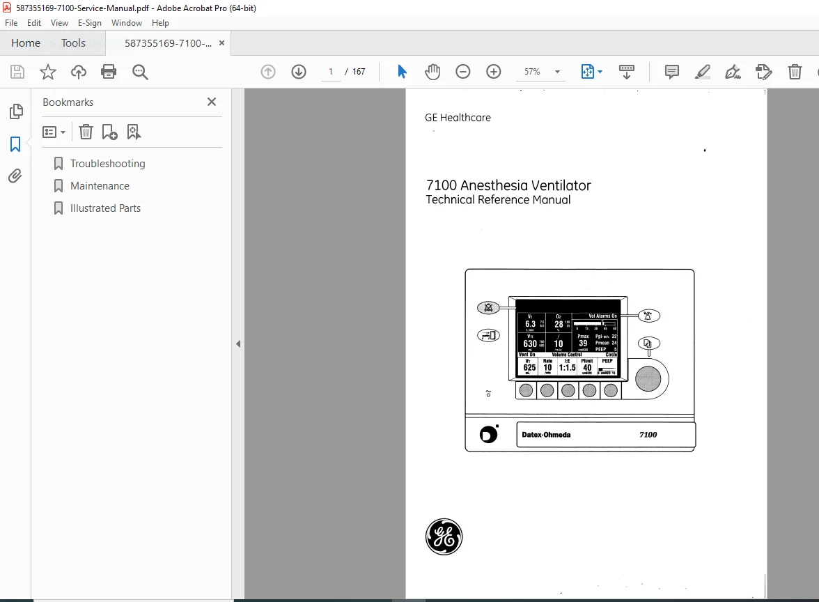
GE Datex-Ohmeda 7100 Anesthesia Ventilator Service Manual PDF
Original price was: $65.00.$14.95Current price is: $14.95.
Official GE Healthcare Datex-Ohmeda 7100 Anesthesia Ventilator technical reference manual for Aestiva and Aespire anesthesia machines (2003). This comprehensive 167-page service manual covers theory of operation, control module service, pneumatic vent engine repair, electronic component diagnostics, calibration procedures, flow sensor zeroing, PEEP valve adjustment, troubleshooting flowcharts, alarm/error codes, maintenance schedules, repair procedures, illustrated parts lists, and complete technical information for biomedical technicians.
Description
GE Datex-Ohmeda 7100 Anesthesia Ventilator Service Manual Aestiva Aespire – PDF DOWNLOAD
DESCRIPTION
This is the official GE Healthcare Datex-Ohmeda 7100 Anesthesia Ventilator Technical Reference Manual (Document 1006-0836-000, February 2003) covering the 7100 ventilator system used in Aestiva and Aespire anesthesia machines. This comprehensive 167-page technical manual provides complete service, maintenance, calibration, troubleshooting, and repair information for qualified biomedical equipment technicians and authorized Datex-Ohmeda service personnel to maintain these critical anesthesia ventilator systems used in operating rooms, surgical centers, and healthcare facilities worldwide.
Product Overview
GE Datex-Ohmeda 7100 Anesthesia Ventilator:
The 7100 represents an advanced anesthesia ventilator system integrated into Aestiva and Aespire anesthesia machines, designed to deliver precise and reliable mechanical ventilation during surgical procedures. This sophisticated system combines electronic control, pneumatic operation, comprehensive monitoring, and multiple safety features to ensure patient safety during anesthesia delivery in operating room environments.
Key Applications:
- Operating room anesthesia delivery
- Surgical procedures
- Intensive care (anesthesia settings)
- Emergency surgery
- Pediatric anesthesia
- Adult anesthesia
- Cardiac surgery
- Neurosurgery
- General surgery
- Outpatient surgery centers
System Integration
Compatible Anesthesia Machines:
- Aestiva Anesthesia Machine (with 7100 ventilator)
- Aespire Anesthesia Machine (with 7100 ventilator)
Serial Number System:
- Format: AAA F 12345
- Year coding (F = 2002, etc.)
- Sequential unit numbering
- Product group identification
Key Features and Safety Systems
7100 Ventilator Features:
- Microprocessor-controlled operation
- Volume-controlled ventilation
- Pressure support modes
- Adjustable respiratory parameters
- Real-time monitoring
- Integrated alarms
- Battery backup operation
- Multiple safety valves
- Compliance compensation
Safety Features:
- Mechanical overpressure valve (MOPV)
- Bellows pressure relief valve
- Free breathing valve
- Backup ventilation modes
- Power failure protection
- Battery backup system
- Alarm systems (visual and audible)
- Pressure monitoring
- Flow monitoring
- Volume monitoring
System Components
Control Module:
- Microprocessor control system
- User interface panel
- LCD display
- Control switches and knobs
- Alarm indicators
- Control board
- Power supply
- Sealed lead-acid battery
Monitoring Interface:
- Flow sensors (inspiratory/expiratory)
- Pressure transducers
- Oxygen sensor
- Signal processing
- Data communication
Serial Interface:
- Communication with anesthesia machine
- Data transfer
- System integration
- Serial adapter board
Pneumatic Vent Engine:
- Inspiratory valve
- PEEP (Positive End-Expiratory Pressure) valve
- Pressure regulator
- Supply gas inlet
- Bellows assembly
- Exhalation control
- Mechanical overpressure valve
- Free breathing valve
- Breathing circuit interface
Comprehensive Manual Contents
DOCUMENT INFORMATION:
- Title: 7100 Anesthesia Ventilator Technical Reference Manual
- Document Number: 1006-0836-000
- Publication Date: February 2003 (02/03)
- Manufacturer: Datex-Ohmeda Inc. (GE Healthcare)
- Address: Ohmeda Drive, PO Box 7550, Madison, Wisconsin 53707
- Pages: 167 pages
- Copyright: © 2003 Datex-Ohmeda Inc.
- PDF Version: 1.6
IMPORTANT NOTICES AND PRECAUTIONS
Service Personnel Requirements:
- Prepared for exclusive use by Datex-Ohmeda service personnel
- Training and experience required
- Availability of proper tools and test equipment
- Must understand manual thoroughly before service
⚠ CAUTION:
- Servicing should never be undertaken without:
- Proper tools and test equipment
- Most recent manual revision
- Clear understanding of procedures
Technical Competence:
- Trained and authorized personnel only
- General knowledge and experience required
- No repairs by unqualified individuals
- Use only genuine Datex-Ohmeda replacement parts
- Read completely through procedures before starting
Documentation:
- Subject to periodic review and updates
- Customers must obtain latest revision
- Comments and suggestions invited
- Contact Manager of Technical Communications
Trademarks:
- Aestiva® – Registered trademark of Datex-Ohmeda Inc.
- Aespire® – Registered trademark of Datex-Ohmeda Inc.
COMPLETE TABLE OF CONTENTS
CHAPTER 1: INTRODUCTION (Pages 1-1 to 1-4)
1.1 What This Manual Includes:
- Manual scope and coverage
- Technical information provided
- Service procedures
- Safety information
1.1.1 Software Versions:
- Software version identification
- Version-specific information
- Compatibility notes
1.2 Standard Service Procedures:
1.2.1 User’s Reference Manuals:
- Operator’s manual references
- User documentation
- Clinical operation guides
1.2.2 Technical Reference Manuals:
- Service documentation
- Technical specifications
- Repair procedures
1.2.3 Ventilator Tests:
- Pre-service testing
- Post-service verification
- Functional testing
- Safety checks
1.3 Symbols Used in Manual or Equipment:
- Warning symbols
- Caution symbols
- Notice symbols
- Electrical symbols
- Pneumatic symbols
- Safety markings
- CE marking (0197)
CHAPTER 2: THEORY OF OPERATION (Pages 2-1 to 2-24)
2.1 General Description (Page 2-2):
- Ventilator overview
- System architecture
- Operating principles
- Integration with anesthesia machine
2.2 7100 Ventilator Features (Page 2-4):
- Ventilation modes
- Control parameters
- Monitoring capabilities
- User interface features
2.2.1 Safety Features (Page 2-4):
- Multiple safety systems
- Redundant protection
- Alarm systems
- Backup ventilation
- Mechanical safety valves
2.3 7100 Ventilator Components (Pages 2-5 to 2-8):
2.3.1 Control Module (Page 2-6):
- Control module overview
- Component layout
- User interface
- Internal components
2.3.2 Monitoring Interface (Page 2-7):
- Sensor systems
- Signal conditioning
- Data acquisition
- Communication
2.3.3 Serial Interface (Page 2-7):
- Communication protocol
- Data transfer
- System integration
- Interface specifications
2.3.4 Pneumatic Vent Engine (Page 2-8):
- Pneumatic system overview
- Gas flow path
- Valve operations
- Pressure control
2.4 Electronic and Electrical Components (Pages 2-9 to 2-18):
2.4.1 Aestiva 7100 Ventilator Functional Blocks (Page 2-9):
- System block diagram
- Component relationships
- Signal flow (Aestiva configuration)
2.4.2 Aespire 7100 Ventilator Functional Blocks (Page 2-10):
- System block diagram
- Component relationships
- Signal flow (Aespire configuration)
2.4.3 Power Supply (Page 2-11):
- AC power input
- Power conversion
- Voltage regulation
- Power distribution
- Protection circuits
2.4.4 Sealed Lead Acid Battery (Page 2-11):
- Battery specifications
- Backup power operation
- Charging circuit
- Battery monitoring
- Replacement requirements
2.4.5 Control Board (Pages 2-12 to 2-15):
- Microprocessor system
- Memory organization
- I/O interfaces
- A/D converters
- Discrete I/O signals
- EEPROM storage
- Control algorithms
- Software architecture
2.4.6 Monitoring Interface (Page 2-16):
- Flow sensor interface
- Pressure transducer interface
- O₂ sensor interface
- Signal processing circuits
- Calibration methods
2.4.7 Serial Interface (Page 2-17):
- Serial communication circuits
- Protocol implementation
- Baud rate settings
- Connector pinouts
2.4.8 Pneumatic Vent Engine Board (Page 2-18):
- Valve driver circuits
- Solenoid control
- Position feedback
- Safety circuits
- Diagnostic features
2.5 Mechanical Subsystems (Pages 2-19 to 2-24):
2.5.1 Supply Gas (Page 2-19):
- Gas supply requirements
- Inlet filtering
- Pressure specifications
- Flow requirements
2.5.2 Pressure Regulator (Page 2-20):
- Regulator function
- Pressure adjustment
- Drive gas pressure
- Regulation accuracy
2.5.3 Inspiratory Valve (Page 2-20):
- Proportional valve operation
- Flow control
- Pressure control
- Valve characteristics
- Response time
2.5.4 Exhalation (PEEP) Control (Page 2-21):
- PEEP valve operation
- Pressure control mechanism
- Adjustment range
- Safety features
- PEEP valve calibration
2.5.5 Bleed Resistor (Page 2-22):
- Function and purpose
- Flow characteristics
- System stability
2.5.6 Bellows Pressure Relief Valve (Page 2-22):
- Overpressure protection
- Operating pressure
- Mechanical operation
- Safety function
2.5.7 Mechanical Overpressure Valve (MOPV) (Page 2-23):
- Primary pressure safety
- Relief pressure setting
- Mechanical operation
- Testing requirements
- Maintenance procedures
2.5.8 Free Breathing Valve (Page 2-23):
- Spontaneous breathing capability
- Valve operation
- Resistance specifications
- Maintenance requirements
2.5.9 Breathing Circuit Flow Sensors (Page 2-24):
- Inspiratory flow sensor
- Expiratory flow sensor
- Differential pressure measurement
- Flow calculation
- Sensor calibration
- Zero offset adjustment
CHAPTER 3: POST-SERVICE CHECKOUT (Pages 3-1 to 3-2)
3.1 Post-Service Checkout (Page 3-2):
- Verification requirements
- Testing sequence
- Documentation requirements
3.1.1 Test the 7100 Ventilator:
- Functional testing
- Calibration verification
- Safety system checks
- Alarm testing
- Performance verification
3.1.2 Test the Anesthesia Machine:
- Complete machine testing
- System integration verification
- Leak testing
- Circuit compliance
- Safety checks
CHAPTER 4: TESTS AND CALIBRATION (Pages 4-1 to 4-40)
4.1 Self Tests (Page 4-2):
- Automatic self-test procedures
- Power-on self-test (POST)
- Continuous monitoring
- Error detection
4.2 Service Mode (Page 4-3):
- Service mode access
- Navigation instructions
- Menu structure
- Security features
4.3 About Ventilator (Page 4-4):
- Software version display
- Hardware configuration
- Serial number
- Operating hours
- Service information
4.4 Alarm Log (Page 4-5):
- Alarm history
- Time-stamped events
- Alarm frequency
- Troubleshooting aid
4.5 Error Log (Page 4-6):
- System error history
- Error codes
- Diagnostic information
- Service records
4.6 Language (Page 4-7):
- Language selection
- Display language
- Available languages
4.7 User Settings (Page 4-8):
4.7.1 Screen Contrast (Page 4-8):
- LCD contrast adjustment
- Visibility optimization
- Setting range
4.8 System Configuration (Page 4-9):
- Configuration options
- Feature enable/disable
- Parameter settings
- Factory defaults
4.9 Calibrations (Pages 4-11 to 4-22):
4.9.1 O₂ Calibrations (Page 4-12):
- Oxygen sensor calibration
- Two-point calibration
- 21% (air) calibration
- 100% oxygen calibration
- Sensor verification
4.9.2 Zero Flow and Airway Sensors (Page 4-13):
- Flow sensor zeroing
- Pressure sensor zeroing
- Zero offset correction
- Ambient pressure compensation
4.9.3 Adjust Drive Gas Regulator (Page 4-14):
- Drive gas pressure adjustment
- Optimal pressure setting
- Pressure verification
- Performance optimization
4.9.4 Airway Sensor Span (Pages 4-15 to 4-16):
- Flow sensor span calibration
- Test fixture requirements
- Calibration procedure
- Accuracy verification
- Span adjustment range
4.9.5 PEEP Valve Calibration (Page 4-17):
- PEEP valve calibration procedure
- Pressure verification
- Adjustment steps
- Acceptance criteria
4.9.6 Inspiratory Valve Calibration (Pages 4-18 to 4-19):
- Inspiratory valve calibration
- Flow control calibration
- Pressure control calibration
- Response characteristics
- Verification testing
4.9.7 Pressure Sensitivity (Pages 4-20 to 4-21):
- Trigger sensitivity calibration
- Patient effort detection
- Adjustment procedure
- Testing requirements
4.9.8 Service Calibrations Required (Page 4-22):
- Mandatory calibrations
- Calibration intervals
- Post-repair calibrations
- Documentation
4.10 Diagnostic Tests/Tools (Pages 4-23 to 4-39):
4.10.1 Display A/D Channels (Pages 4-24 to 4-25):
- Analog-to-digital converter values
- Sensor readings
- Real-time display
- Diagnostic information
4.10.2 Display Discrete I/O Signals (Page 4-26):
- Digital input/output status
- Switch states
- Valve states
- LED status
4.10.3 Display Battery Status (Page 4-27):
- Battery voltage
- Charging status
- Battery health
- Replacement indicators
4.10.4 Test Panel Switches (Page 4-28):
- Front panel switch testing
- Switch functionality
- Input verification
4.10.5 Valves – Test Tool (Page 4-29):
- Manual valve control
- Valve function testing
- Inspiratory valve test
- PEEP valve test
- Actuator verification
4.10.6 Test CPU and Memory (Page 4-30):
- Processor testing
- RAM testing
- ROM testing
- Checksum verification
4.10.7 Test EEPROM (Page 4-31):
- Non-volatile memory testing
- Data integrity verification
- Read/write testing
4.10.8 Test Serial Port (Page 4-32):
- Serial communication testing
- Loopback testing
- Data transmission
- Protocol verification
4.10.9 Test 5V Fail Alarm (Page 4-33):
- Power supply alarm testing
- Voltage monitoring
- Alarm activation
- Safety verification
4.10.10 Test Inspiratory Valve (Page 4-34):
- Inspiratory valve functional test
- Position control
- Flow verification
- Response testing
4.10.11 Test PEEP Valve (Page 4-35):
- PEEP valve functional test
- Pressure control
- Position verification
- Response testing
4.10.12 Test PEEP Safety Valve (Page 4-36):
- Safety valve operation
- Relief pressure verification
- Mechanical function
4.10.13 Breathing System Leak Test (Page 4-37):
- System integrity testing
- Leak detection
- Pressure decay measurement
- Acceptance criteria
4.10.14 Test Pressure Limit Circuit (Pages 4-38 to 4-39):
- Pressure limiting function
- Safety circuit testing
- Alarm verification
- Protection testing
4.11 Upgrade Options (Page 4-40):
- Software upgrades
- Feature activation
- Option enabling
- License management
CHAPTER 5: TROUBLESHOOTING (Pages 5-1 to 5-21)
5.1 Troubleshooting Instructions (Page 5-2):
- Systematic approach
- Safety precautions
- Required tools
- Documentation
5.2 Troubleshooting Guide (Pages 5-2 to 5-3):
- Problem identification
- Symptom-based approach
- Decision trees
- Component isolation
5.3 Alarm and Error Messages (Pages 5-4 to 5-14):
Complete Alarm/Error Code Listings:
- Code numbers and descriptions
- Probable causes
- Corrective actions
- System diagnostics
- Component failures
- Sensor errors
- Calibration errors
- Communication errors
- Power failures
- Mechanical failures
- Safety alarms
For Each Alarm/Error:
- Description
- Displayed message
- Possible causes
- Troubleshooting steps
- Corrective procedures
- Preventive measures
5.4 Troubleshooting Flowcharts (Pages 5-15 to 5-21):
5.4.1 Ventilator Assessment Process (Page 5-15):
- Initial assessment flowchart
- Problem categorization
- Diagnostic path selection
5.4.2 No Display Troubleshooting (Page 5-16):
- Power supply verification
- Battery testing
- Display circuit testing
- Control board diagnostics
- Connection verification
5.4.3 Inaccurate Volume Ventilation Troubleshooting (Pages 5-17 to 5-18):
- Volume accuracy issues
- Flow sensor problems
- Calibration verification
- Leak detection
- Valve testing
- Compliance issues
5.4.5 VMB Board Evaluation – Aespire Machine (Page 5-19):
- Ventilator Monitor Board diagnostics
- Board-specific testing
- Signal verification
- Aespire configuration
5.4.6 No Ventilation Troubleshooting (Page 5-20):
- Complete ventilation failure
- Supply gas verification
- Valve testing
- Control system diagnostics
- Pneumatic circuit testing
- Safety valve verification
5.4.7 High Intrinsic PEEP Troubleshooting (Page 5-21):
- Exhalation valve problems
- PEEP valve calibration
- Circuit resistance
- Flow sensor issues
- Mechanical obstructions
CHAPTER 6: MAINTENANCE (Pages 6-1 to 6-4)
6.1 Maintenance Schedule (Page 6-2):
- Preventive maintenance intervals
- Routine maintenance tasks
- Inspection schedules
- Calibration intervals
- Component replacement schedules
- Documentation requirements
6.2 Free Breathing Valve Maintenance (Page 6-3):
- Cleaning procedures
- Inspection criteria
- Functional testing
- Replacement criteria
- Reassembly procedures
6.3 MOPV Pressure Relief Valve Test (Page 6-4):
6.3.1 Test Setup:
- Required equipment
- Test configuration
- Connection procedures
- Safety precautions
6.3.2 Test Procedure:
- Pressure application
- Relief pressure measurement
- Acceptance criteria (typically 75-80 cmH₂O)
- Adjustment procedures
- Retest verification
CHAPTER 7: REPAIR PROCEDURES (Pages 7-1 to 7-20)
7.1 Software Installation (Pages 7-2 to 7-3):
- Software download procedures
- Installation requirements
- Update procedures
- Verification testing
7.1.1 After Replacing Control Board or Control Module:
- Post-replacement procedures
- Software installation
- Configuration transfer
- Calibration requirements
- Verification testing
7.2 Control Module (Pages 7-4 to 7-10):
7.2.1 Inside the Control Module (Page 7-5):
- Component layout
- Internal access
- Component identification
7.2.2 Control Board (Page 7-6):
- Board removal procedures
- Connector identification
- Installation procedures
- Torque specifications
- ESD precautions
7.2.3 Battery and Power Supply (Page 7-7):
- Battery replacement
- Power supply removal
- Installation procedures
- Polarity verification
- Testing procedures
7.2.4 Front Enclosure with Control Board Removed (Page 7-8):
- Access to internal components
- Component removal
- Wire routing
7.2.5 Front Enclosure Components (Pages 7-9 to 7-10):
- Display module
- Switch assemblies
- LED indicators
- Connector panels
- Gaskets and seals
7.3 Pneumatic Engine (Pages 7-11 to 7-18):
7.3.1 Pneumatic Engine in Aestiva Machine (Page 7-11):
- Location and access
- Removal procedures
- Installation procedures
- Aestiva-specific configuration
7.3.2 Pneumatic Vent Engine in Aespire Machine (Page 7-12):
- Location and access
- Removal procedures
- Installation procedures
- Aespire-specific configuration
7.3.3 Pneumatic Engine Components – Aespire (Page 7-13):
- Component identification
- Assembly breakdown
- Replacement procedures
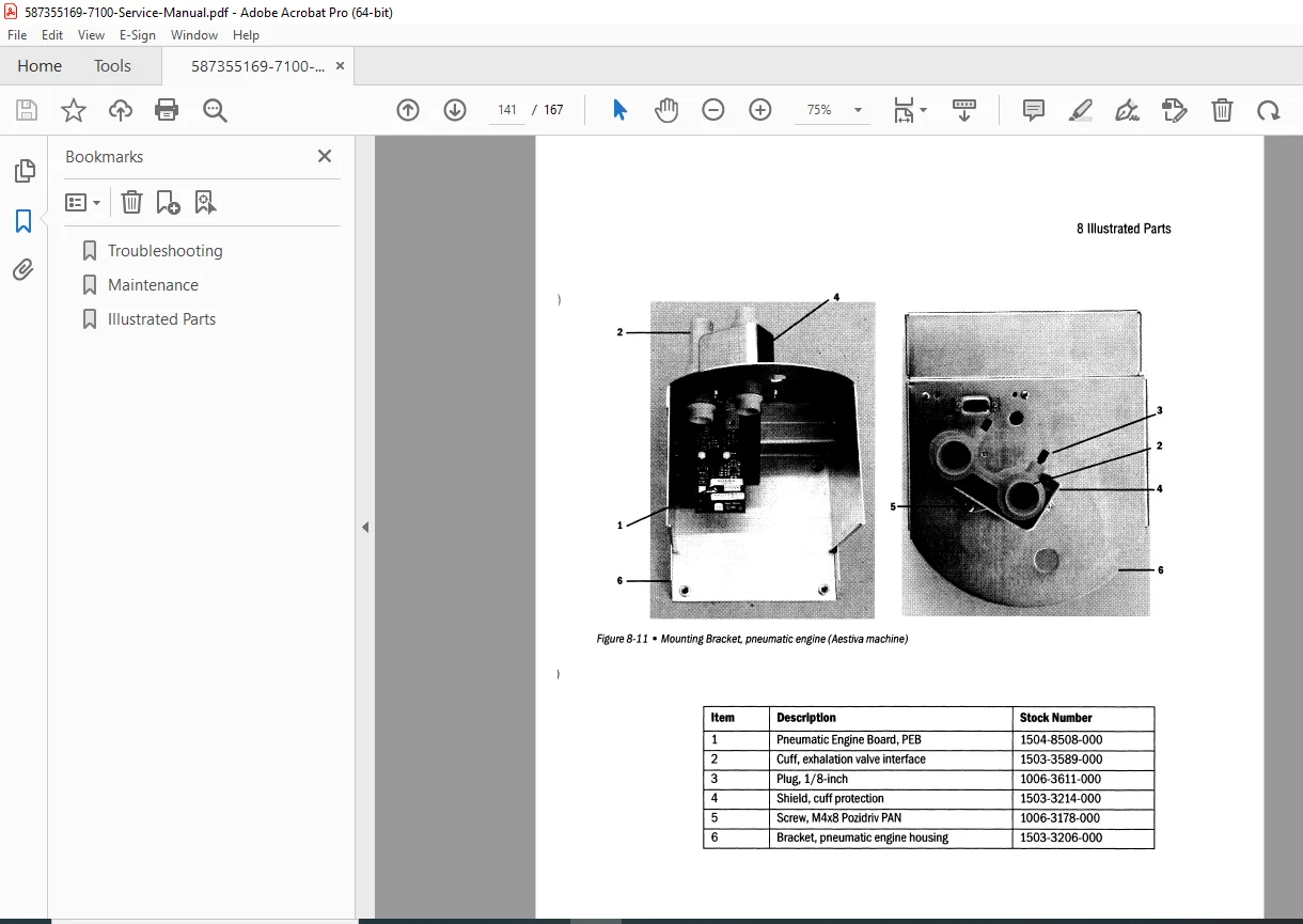
7.3.4 Pneumatic Engine Components – Aestiva (Page 7-14):
- Component identification
- Assembly breakdown
- Replacement procedures
7.3.5 Supply Gas Inlet Filter – Aestiva (Page 7-15):
- Filter location
- Replacement procedure
- Filter specifications
- Installation verification
7.3.6 Insp/PEEP Interface Assembly and Reservoir (Page 7-16):
- Interface removal
- Component replacement
- O-ring replacement
- Assembly procedures
- Leak testing
7.3.7 Manifold and Plate Assembly (Page 7-17):
- Manifold removal
- Component inspection
- Gasket replacement
- Torque specifications
- Leak testing
7.3.8 Pneumatic Engine Board and Housing – Aestiva (Page 7-18):
- Board removal
- Housing disassembly
- Component replacement
- Reassembly procedures
7.4 Monitoring Interface Assembly (MIA) – Aestiva Machine (Page 7-19):
- MIA location
- Removal procedures
- Sensor replacement
- Installation procedures
- Calibration requirements
7.5 Serial Adapter Board (SAB) and Power Cord/Harness (Page 7-20):
- SAB location
- Removal procedures
- Power cord replacement
- Harness routing
- Connection verification
CHAPTER 8: ILLUSTRATED PARTS (Pages 8-1 to 8-X)
8.1 Special Instructions (Page 8-2):
- Parts ordering information
- Part number references
- Special handling requirements
- Obsolescence notices
8.2 Service Tools (Page 8-2):
- Required service tools list
- Special tools
- Test equipment
- Calibration fixtures
- Tool part numbers
8.3 7100 Ventilator Parts (Page 8-3 onwards):
Exploded View Diagrams:
- Control module assembly
- Pneumatic engine assembly
- Valve assemblies
- Sensor assemblies
- Electrical components
- Mechanical components
Parts Lists:
- Part numbers
- Descriptions
- Quantities
- Reference designators
- Assembly notes
- Superseded parts
Major Assemblies:
- Control board assembly
- Power supply assembly
- Battery assembly
- Pneumatic engine board
- Inspiratory valve assembly
- PEEP valve assembly
- Flow sensor assemblies
- Pressure transducers
- O₂ sensor
- Display module
- Switch assemblies
- Gaskets and seals
- Hardware kits
- Cable assemblies
CHAPTER 9: SCHEMATICS AND DIAGRAMS (Pages 9-1 to 9-X)
Electrical Schematics:
- Power supply schematic
- Control board schematic
- Battery charging circuit
- Serial interface schematic
- Monitoring interface schematic
- Pneumatic engine board schematic
- Switch and LED circuits
- Alarm circuits
Block Diagrams:
- System architecture
- Signal flow diagrams
- Power distribution
- Communication buses
- Aestiva configuration
- Aespire configuration
Pneumatic Diagrams:
- Gas flow paths
- Valve operation
- Pressure regulation
- Breathing circuit
- Safety systems
Wiring Diagrams:
- Control module wiring
- Inter-board connections
- Cable routing
- Connector pinouts
- Harness diagrams
Component Locations:
- PCB component layouts
- Test points
- Adjustment points
- Sensor locations
- Connector locations
Who Needs This Manual?
This GE Datex-Ohmeda 7100 Anesthesia Ventilator service manual is essential for:
- Datex-Ohmeda authorized service technicians
- Hospital biomedical engineering departments
- Anesthesia equipment service specialists
- GE Healthcare service centers
- Clinical engineering professionals
- Anyone performing authorized service on 7100 ventilators
Prerequisites:
✓ Datex-Ohmeda service training
✓ Anesthesia equipment experience
✓ Understanding of ventilator principles
✓ Electronic troubleshooting skills
✓ Pneumatic system knowledge
✓ Biomedical equipment service experience
✓ Patient safety awareness
✓ Proper tools and test equipment
✓ Current manual revision
FILE DETAILS
| Detail | Specification |
|---|---|
| Manual Title | 7100 Anesthesia Ventilator Technical Reference Manual |
| Used In | Aestiva and Aespire Anesthesia Machines |
| Document Number | 1006-0836-000 |
| Publication Date | February 2003 (02/03) |
| Manufacturer | Datex-Ohmeda Inc. (GE Healthcare) |
| Pages | 167 pages |
| PDF Quality | Professional technical manual with detailed diagrams |
| File Size | 13.5 MB |
| Page Size | A4 (595.08 x 842.04 pts) |
| Language | English |
| Creator | PDF reDirect v2 |
| PDF Version | 1.6 |
| Copyright | © 2003 Datex-Ohmeda Inc. |


