GE LOGIQ e Ultrasound Service Manual PDF (2007)
Original price was: $95.00.$30.95Current price is: $30.95.
Download the official GE LOGIQ e ultrasound service manual PDF, including detailed GE Healthcare ultrasound maintenance instructions, LOGIQ e diagnostics troubleshooting manual guidance, and LOGIQ e repair guide PDF procedures. This 2007 revision covers installation, functional checks, components theory, replacement parts list PDF, and ultrasound system periodic maintenance guide for safe, efficient servicing of models like 5151219-5151253. Essential for technicians ensuring optimal performance
Description
GE LOGIQ e Ultrasound Service Manual (2007) PDF DOWNLOAD
Description: Gain access to the comprehensive GE LOGIQ e ultrasound service manual PDF, an indispensable LOGIQ e repair guide PDF from GE Healthcare. This detailed document provides GE Healthcare ultrasound maintenance instructions, LOGIQ e diagnostics troubleshooting manual insights, and step-by-step procedures for installation, adjustments, and repairs. Issued in 2007 as Direction 5197051-100 Revision 1, it emphasizes safety precautions, electrical compliance, and system optimization for the LOGIQ e ultrasound scanning system across various regional models.
Ideal for service personnel, hospital technicians, and contractors, this manual includes warnings on hazards, EMC/EMI/ESD considerations, and customer assistance contacts. It ensures proper handling to prevent injury or equipment damage, with guidance on returning probes and using certified contractors for electrical work.
File Details:
- Manual Name: GE Healthcare LOGIQ™ e Service Manual
- Models Covered: 5151219 (USA), 5151220 (Argentina), 5151243 (Europe), 5151247 (China), 5151252 (Japan), 5151253 (Australia), 5151251 (India)
- Year: 2007
- Manual PDF Quality: High-resolution with clear text, tables, diagrams, and searchable content
- Number of Pages: 211
Table of Contents: The manual’s table of contents is extensively detailed, organized by chapters with subsections for easy reference. Here’s a neatly categorized extraction:
- Chapter 1: Introduction
- Overview – 1-1
- Purpose of Chapter 1 – 1-1
- Chapter Contents – 1-1
- Typical Users of the Basic Service Manual – 1-2
- LOGIQ™ e Models Covered by this Manual – 1-2
- Purpose of Operator Manual(s) – 1-2
- Important Conventions – 1-3
- Conventions Used in Book – 1-3
- Safety Considerations – 1-7
- Introduction – 1-7
- Human Safety – 1-7
- Mechanical Safety – 1-7
- Battery Safety – 1-10
- Dangerous Procedure Warnings – 1-11
- Lockout/Tagout Requirements (For USA Only) – 1-11
- Returning/Shipping Probes and Repair Parts – 1-11
- EMC, EMI, and ESD – 1-12
- Electromagnetic Compatibility (EMC) – 1-12
- CE Compliance – 1-12
- Electrostatic Discharge (ESD) Prevention – 1-12
- Customer Assistance – 1-13
- Contact Information – 1-13
- System Manufacturer – 1-14
- Chapter 2: Pre-Installation
- Overview – 2-1
- Purpose of this chapter 2 – 2-1
- Chapter Contents – 2-1
- General Console Requirements – 2-2
- Console Environmental Requirements – 2-2
- Lighting – 2-2
- Electrical Requirements – 2-2
- LOGIQ™ e Power Requirements – 2-2
- Inrush Current – 2-3
- Site Circuit Breaker – 2-3
- Site Power Outlets – 2-3
- Unit Power Plug – 2-3
- Power Stability Requirements – 2-3
- EMI Limitations – 2-4
- Facility Needs – 2-6
- Purchaser Responsibilities – 2-6
- Required Features – 2-7
- Desirable Features – 2-7
- Recommended and Alternate Ultrasound Room Layout – 2-8
- Stand Alone Scanner (without Network Connection) – 2-9
- Scanner Connected to Hospital’s Network – 2-9
- Purpose of DICOM Network Function – 2-9
- DICOM Option Pre-installation Requirements – 2-9
- Chapter 3: Installation
- Overview – 3-1
- Purpose of Chapter 3 – 3-1
- Average Installation Time – 3-1
- Installation Warnings – 3-2
- Safety Reminders – 3-2
- Receiving and Unpacking the Equipment – 3-3
- Moving into Position – 3-6
- Packing the Equipment – 3-6
- Preparing for Installation – 3-7
- Verify Customer Order – 3-7
- Physical Inspection – 3-7
- System Voltage Settings – 3-7
- EMI Protection – 3-7
- Completing the Installation – 3-8
- Power On / Boot Up – 3-8
- Scanner Power On – 3-8
- Turn on the system – 3-9
- Power Off/ Shutdown – 3-9
- Back-end Processor Power Down – 3-9
- Scanner Shutdown – 3-10
- Transducer Connection – 3-10
- System Configuration – 3-11
- System Specifications – 3-11
- Physical Dimensions – 3-11
- Electrical Specifications – 3-12
- Approved on-board peripherals – 3-12
- Connecting Cables – 3-13
- Peripherals/Accessories Connector Panel – 3-13
- Rear Panel Connector – 3-13
- Left Panel Connector – 3-14
- This section indicates the pin assignment for each connector. – 3-15
- Connect peripherals – 3-16
- Available Probes – 3-22
- Software/Option Configuration – 3-22
- Connectivity Installation Worksheet – 3-23
- Loading Base Image Software – 3-24
- Software Version check out – 3-27
- Functional Check-out – 3-27
- Paperwork – 3-28
- Product Locator Installation – 3-28
- User Manual(s) – 3-28
- Chapter 4: Functional Checks
- Overview – 4-1
- Purpose for Chapter 4 – 4-1
- Required Equipment – 4-1
- General Procedure – 4-2
- Power On/Boot Up – 4-2
- Scanner Power On – 4-2
- Turn on the system – 4-3
- Power Off/ Shutdown – 4-3
- Back-end Processor Power Down – 4-3
- Scanner Shutdown – 4-4
- Full Maintenance Reboot – 4-4
- Archiving and Loading Presets – 4-5
- Archiving Presets to an DVD-R Disk (or USB memory device) – 4-5
- Loading Presets from an DVD-R disk (or USB memory device) – 4-6
- Adjusting the Display Monitor – 4-6
- Lockout/Tagout Requirements (For USA Only) – 4-6
- System Features – 4-7
- Control Panel – 4-7
- LOGIQ™ e SoftMenu Key Tour – 4-8
- Monitor Display – 4-9
- Preparations – 4-10
- B Mode OP Panel Controls – 4-11
- B Mode Softmenu Key – 4-12
- Preparations – 4-13
- M Mode OP Panel Controls – 4-14
- M Mode Softmenu Key – 4-15
- Preparations – 4-16
- Color Flow Mode OP Panel Controls – 4-17
- Color Flow Mode Softmenu Key – 4-18
- Preparations – 4-20
- Doppler Mode OP Panel Controls – 4-21
- Doppler Mode OP Panel Controls – 4-22
- Basic Measurements – 4-24
- Distance and Tissue Depth Measurements – 4-24
- Circumference/Area (Ellipse) Measurement – 4-24
- Worksheets – 4-24
- Probe/Connectors Usage – 4-25
- Connecting a probe – 4-25
- Activating the probe – 4-25
- Deactivating the probe – 4-25
- Disconnecting the probe – 4-25
- Using Cine – 4-25
- Activating CINE – 4-25
- Quickly Move to Start/End Frame – 4-25
- Start Frame/End Frame – 4-26
- Adjusting the CINE Loop Playback Speed – 4-26
- Moving through a CINE Loop Frame By Frame – 4-26
- Image Management (QA) – 4-26
- Formatting Media – 4-27
- Backup System Presets and Configurations – 4-28
- Restore System Presets and Configurations – 4-29
- Archiving Images – 4-30
- Emergency Repair Disk – 4-32
- Software Configuration Checks – 4-36
- Peripheral Checks – 4-36
- Chapter 5: Components and Functions (Theory)
- Overview – 5-1
- Block Diagrams and Theory – 5-2
- Block Diagram – 5-2
- General Information – 5-3
- Front End – 5-4
- The Back End – 5-5
- Top Console – 5-5
- External I/O – 5-6
- Peripherals – 5-6
- Wiring – 5-7
- PWA Assy Diagrams – 5-8
- TMST – 5-8
- Description – 5-10
- RX64 – 5-11
- Description – 5-11
- TX64 – 5-12
- Description – 5-12
- CWD – 5-13
- Description – 5-13
- Keyboard – 5-14
- Scan Control Board LEDs – 5-15
- Power Diagrams – 5-16
- Overview – 5-16
- AC Power – 5-16
- Battery charging – 5-17
- Air Flow Distribution – 5-18
- Fans – 5-19
- Common Service Platform – 5-20
- Introduction – 5-20
- Internationalization – 5-20
- Service Login – 5-20
- Access / Security – 5-20
- The usage for security cable – 5-21
- Logs – 5-24
- Utilities – 5-25
- Search – 5-25
- Exit – 5-26
- Diagnostics Execution – 5-27
- Diagnostic Reports – 5-27
- Calibration – 5-28
- Utilities – 5-29
- Replacement – 5-30
- PM – 5-30
- Chapter 6: Service Adjustments
- Overview – 6-1
- Purpose of this chapter 6 – 6-1
- Monitor Adjustments – 6-2
- Adjustments Procedures – 6-2
- Chapter 7: Diagnostics/Troubleshooting
- Overview – 7-1
- Purpose of Chapter 7 – 7-1
- Gathering Trouble Data – 7-2
- Overview – 7-2
- Collect Vital System Information – 7-2
- USB Quick Save – 7-4
- Overview – 7-4
- Check and Record the P3 Key Function – 7-4
- Setting the P3 Key to USB Quick Save – 7-5
- Screen Captures – 7-6
- Check and Record the P3 Key Function – 7-6
- Setting the P3 Key to Screen Capture – 7-6
- Reset the P3 Key to Customer’s Functionality – 7-8
- Global Service User Interface (GSUI) – 7-9
- Enter global service user interface – 7-9
- Active Diagnostic Function – 7-10
- Button – 7-10
- Loop Count – 7-10
- Progress Indicator – 7-10
- Short Text Message – 7-11
- Background Color – 7-11
- Common Diagnostics – 7-12
- Utilities – 7-12
- Disruptive Mode – 7-12
- System Shutdown – 7-12
- Essential Tests – 7-13
- System Board – 7-13
- Hard Disk Surface Scan – 7-13
- Hard Disk Quick Test – 7-13
- PCIbus – 7-13
- Video Card – 7-13
- Network Interface – 7-13
- CMOS – 7-13
- DRAM Memory – 7-13
- Parallel Port – 7-13
- Keyboard Test – 7-14
- Mouse Test – 7-14
- Restart LOGIQ™ e After Diagnostics – 7-14
- Network and Insite II Configuration – 7-15
- Network Configuration – 7-15
- Wire-LAN Network – 7-15
- Wireless LAN Network – 7-17
- Insite II Configuration – 7-20
- Chapter 8: Replacement Procedures
- Overview – 8-1
- Purpose of Chapter – 8-1
- Disassembly/Re-assembly – 8-2
- Warning and Caution – 8-2
- Handle Assy (FRU No. 313) – 8-2
- Tools – 8-2
- Needed Manpower – 8-2
- Preparations – 8-2
- Removal Procedure – 8-2
- Mounting procedure – 8-2
- Chapter 9: Renewal Parts
- Overview – 9-1
- Purpose of Chapter 9 – 9-1
- List of Abbreviations – 9-1
- Renewal Parts Lists – 9-2
- Equipment Models Covered in this Chapter – 9-2
- Operator Console Assy – 9-3
- LCD Assy – 9-4
- Keyboard Assy – 9-6
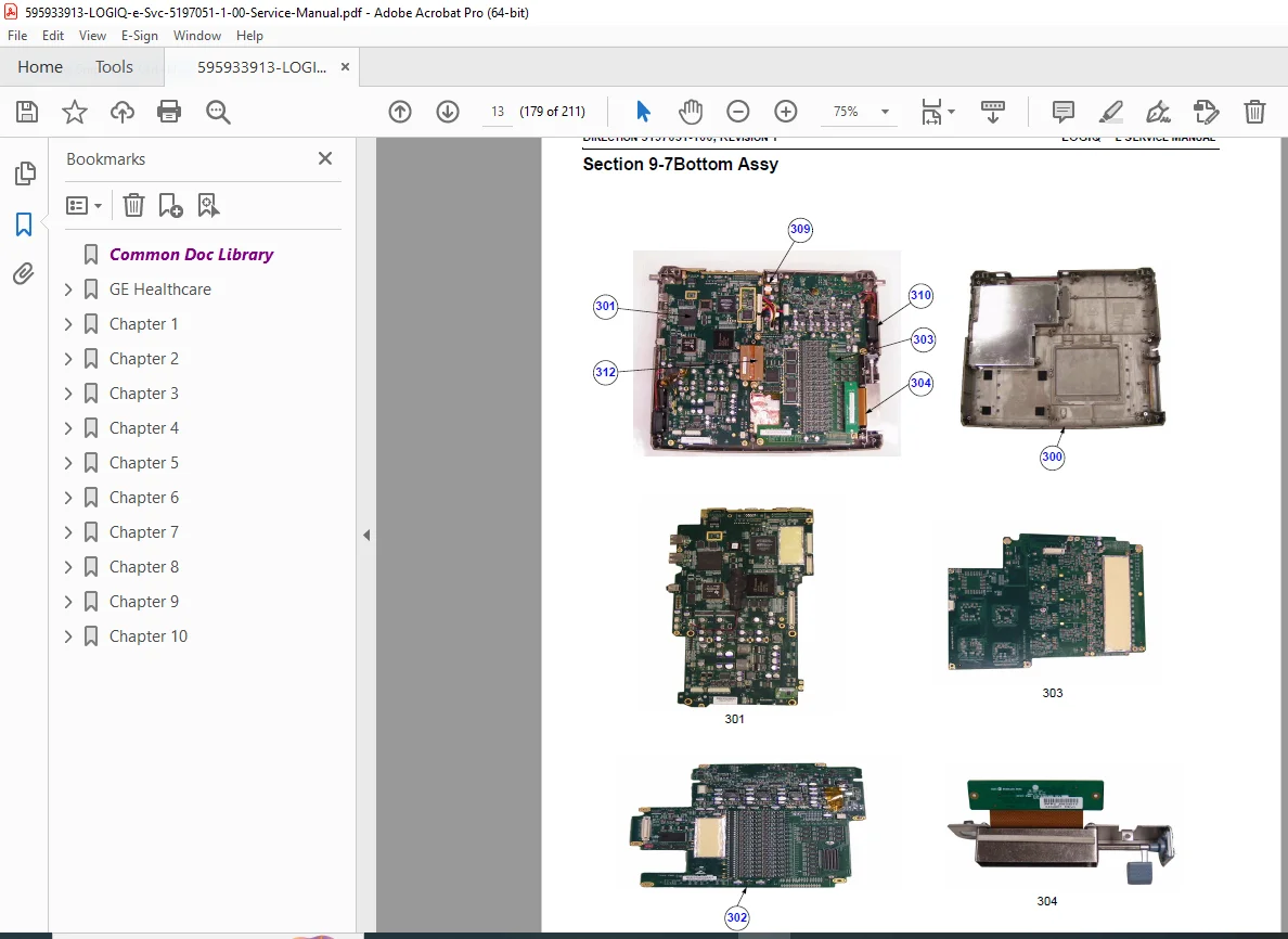
- Bottom Assy – 9-8
- Cables – 9-12
- Isolation Cart Components – 9-13
- Accessories and Kits – 9-14
- Manuals – 9-16
- Probe – 9-16
- Chapter 10: Care & Maintenance
- Overview – 10-1
- Periodic Maintenance Inspections – 10-1
- Purpose of Chapter 10 – 10-1
- Why do Maintenance – 10-2
- Keeping Records – 10-2
- Quality Assurance – 10-2
- Maintenance Task Schedule – 10-2
- How often should care & maintenance tasks be performed? – 10-2
- Tools Required – 10-4
- Special Tools, Supplies and Equipment – 10-4
- Specific Requirements for Care & Maintenance – 10-4
- System Maintenance – 10-5
- Preliminary Checks – 10-5
- System Checks – 10-6
- Peripheral/Option Checks – 10-7
- Input Power – 10-7
- AC/DC Adapter Inspection – 10-7
- Cleaning – 10-7
- General Cleaning – 10-7
- Physical Inspection – 10-8
- View the Logs – 10-9
- Probe Maintenance – 10-9
- Probe Related Checks – 10-9
- Basic Probe Care – 10-9
- Basic Probe Cleaning – 10-9
- Using a Phantom – 10-10
- Electrical Safety Tests – 10-10
- Safety Test Overview – 10-10
- Definition – 10-13
- Generic Procedure – 10-13
- Data Sheet for enclosure Source Leakage Current – 10-14
- Definition – 10-15
- Generic Procedure – 10-15
- No Meter Probe Adapter Procedure – 10-16
- Data Sheet for Transducer Source Leakage Current – 10-17
- When There’s Too Much Leakage Current… – 10-18
No separate index is present; the TOC serves as the primary navigation, with an alphabetical index mentioned in the List of Effective Pages (pages I to II).
Empower your servicing with this GE LOGIQ e ultrasound service manual PDF—download instantly for immediate access to critical LOGIQ e diagnostics troubleshooting manual tools and ultrasound system periodic maintenance guide, minimizing downtime and ensuring precision in every repair!